NCR OPTIC 12 User manual

Installation Instructions
NCR OPTIC12 Printer for GVR Encore 500s
Kit Number: 6003-0100-8801
497-0517248
Issue B

The product described in this document is a licensed product of NCR Corporation.
NCR is a registered trademark of NCR Corporation. NCR RealPOS is a trademark of NCR Corporation in
the United States and/or other countries. Other product names mentioned in this publication may be
trademarks or registered trademarks of their respective companies and are hereby acknowledged.
The terms HDMI and HDMI High-Definition Multimedia Interface, and the HDMI Logo are trademarks
or registered trademarks of HDMI Licensing LLC in the United States and other countries.
Where creation of derivative works, modifications or copies of this NCR copyrighted documentation is
permitted under the terms and conditions of an agreement you have with NCR, NCR's copyright notice
must be included.
It is the policy of NCR Corporation (NCR) to improve products as new technology, components,
software, and firmware become available. NCR, therefore, reserves the right to change specifications
without prior notice.
All features, functions, and operations described herein may not be marketed by NCR in all parts of the
world. In some instances, photographs are of equipment prototypes. Therefore, before using this
document, consult with your NCR representative or NCR office for information that is applicable and
current.
To maintain the quality of our publications, we need your comments on the accuracy, clarity,
organization, and value of this book. Please use the link below to send your comments.
EMail: FD230036@ncr.com
Copyright © 2017
By NCR Corporation
Duluth, GA U.S.A.
All Rights Reserved

Document Number
DCV-00213
Date Released
May. 2017
Revision Number/Security level
R01 S2
Retrofit G7 Printer GVR Encore 500S (US) Installation Guide
Retrofit G7 Printer
GVR Encore 500S (US)
Installation Guide
Kit Part Number: 6003-0100-8801

2
Document Number
DCV-00213
Date Released
May. 2017
Revision Number/Security level
R01 S2
Retrofit G7 Printer GVR Encore 500S (US) Installation Guide
Release History
Version
Prepared by
Date
Change description
0
Invenco Group Ltd
December 2016
Initial version to be approved by UL
1
Invenco Group Ltd
May 2017
Front page, “Kit Part Number” reference
corrected
© 2016 by Invenco Group Limited
All rights reserved
No part of this document may be copied or reproduced in any form without prior written consent from Invenco.
Invenco has taken great effort to verify the accuracy of this document but assumes no responsibility for any technical inaccuracies or
typographical errors

3
Document Number
DCV-00213
Date Released
May. 2017
Revision Number/Security level
R01 S2
Retrofit G7 Printer GVR Encore 500S (US) Installation Guide
Contents
Release History.......................................................................................................................................2
1Introduction......................................................................................................................................5
1.1 Tools Required........................................................................................................................5
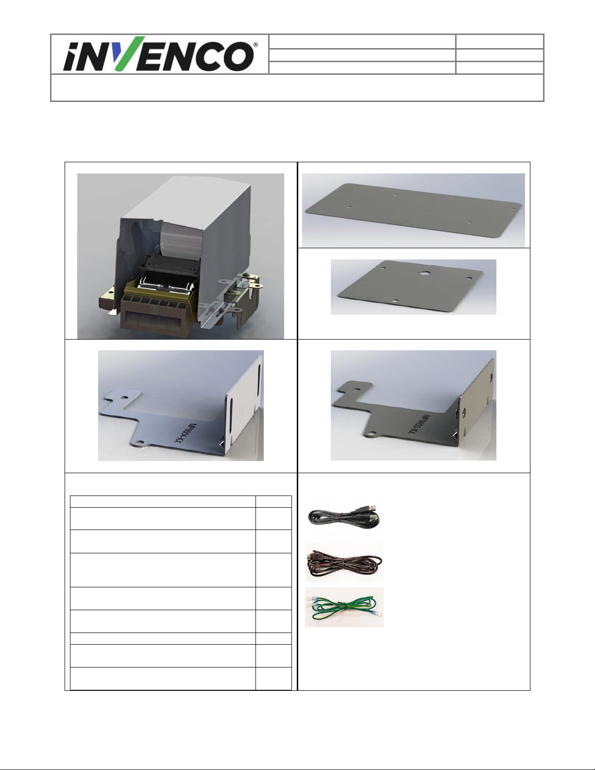
1.2 Installation Kit Contents ..........................................................................................................6
2Safety & Compliance Information....................................................................................................7
2.1 Preliminary Precautions ..........................................................................................................7
2.2 Emergency Total Electrical Shut-Off.......................................................................................7
2.3 Total Electrical Shut-Off Before Access..................................................................................7
2.4 Evacuation, Barricading and Shut-Off.....................................................................................7
2.5 Read the Manual.....................................................................................................................7
2.6 Follow the Regulations............................................................................................................8
2.7 Replacement Parts..................................................................................................................8
3Safety Symbols and Terminology ...................................................................................................8
3.1 Prevent Explosions and Fires .................................................................................................8
3.1.1 No Open Flames.............................................................................................................9
3.1.2 No Sparks - No Smoking.................................................................................................9
3.1.3 Working Alone.................................................................................................................9
3.1.4 Working with Electricity Safety........................................................................................9
3.1.5 Hazardous Materials .......................................................................................................9
3.1.6 In an Emergency.............................................................................................................9
3.1.7 Approvals ......................................................................................................................10
3.2 Computer Programs and Documentation .............................................................................10
4Disassembly..................................................................................................................................11
5Pre-Installation ..............................................................................................................................16
6Installation.....................................................................................................................................19
6.1 Determine the Pulser type.....................................................................................................19
6.1.1 No Pulser.......................................................................................................................19
6.1.2 Pulser Type 1: Small plastic pulser on a plastic base...................................................20
6.1.3 Pulser Type 2: Large plastic pulser on a plastic base...................................................20
6.1.4 Pulser Type 3: Large plastic pulser on a 2-screw small metal base.............................21
6.1.5 Pulser Type 4: Large plastic pulser on a 3-screw large metal base.............................21
6.1.6 Pulser Type 5: Large plastic pulser on a 3-screw small metal base.............................22
6.1.7 Pulser Type 6: Small metal pulser on a 2-screw small metal base ..............................22
6.2 Install the Foot Bracket Assemblies......................................................................................23
6.2.1 No Pulser: Installing the Printer Feet ............................................................................23
6.2.2 Pulser Type 1: Installing the Printer Feet......................................................................25
6.2.3 Pulser Type 2: Installing the Printer Feet......................................................................27
6.2.4 Pulser Type 3: Installing the Printer Feet......................................................................29
6.2.5 Pulser Type 4: Installing the Printer Feet......................................................................32
6.2.6 Pulser Type 5: Installing the Printer Feet......................................................................35
6.2.7 Pulser Type 6: Installing the Printer Feet......................................................................39
6.3 Install the Printer Mounting Platform onto the Foot Brackets ...............................................44
6.4 Install the Printer onto the Printer Mounting Platform...........................................................48
6.5 Final Adjustments..................................................................................................................49

4
Document Number
DCV-00213
Date Released
May. 2017
Revision Number/Security level
R01 S2
Retrofit G7 Printer GVR Encore 500S (US) Installation Guide
6.6 Cable Installation...................................................................................................................54
6.7 Installation of Letterbox Cover ..............................................................................................58
6.8 Install Completion..................................................................................................................59

5
Document Number
DCV-00213
Date Released
May. 2017
Revision Number/Security level
R01 S2
Retrofit G7 Printer GVR Encore 500S (US) Installation Guide
1 Introduction
The documentation provides some basic guidelines for installing the Optic 12 / G7 Printer into a GVR
Encore 500S dispenser.
This Retro-Fit Kit:
•can only be installed in combination with any of these UL Listed by Report Retrofit Kits:
o6002-0001-8801,
o6002-0004-8801,
o6002-0005-8801;
•can be installed into either Side A or Side B the dispenser;
•is for a single Side. For a double-sided installation, two of these Kits are required.
1.1 Tools Required
The following tools are required to mount the G7 OPT:
•Gilbarco “CH 751” Key
•Gilbarco “GBCO” Key
•Flat 5mm screwdriver
•Side cutters
•Cable (zip) ties
•Needle Nose Pliers
•5/16” Socket or Nut Driver
•10mm Socket or Nut Driver
•10mm Ring Spanner
•6” ruler (150mm ruler)
WARNING
Do NOT use power tools if working on a fuel station forecourt.
Any spark could cause an explosion.

6
Document Number
DCV-00213
Date Released
May. 2017
Revision Number/Security level
R01 S2
Retrofit G7 Printer GVR Encore 500S (US) Installation Guide
1.2 Installation Kit Contents
Unpack the Retro-Fit Kit and check that all of the parts listed below are present.
Printer Assembly (MZ0086):
Blank Base Plate (MP0649):
Pulser Type 6 Plate (MP0650) QTY = 2:
Foot Bracket Left (MP0604):
Distinguishing feature: vertical slots
Foot Bracket Right (MP0605):
Distinguishing feature: threaded inserts
Sundry Parts (FK0010):
Comprising:
ITEM
QTY
MN0031 NUT, SEMS, #8-32 UNC,
EXTERNAL STAR WASHER, SS304
2
MW0046 WASHER, #10 X 3/4" OD,
SS304, ZINC
1
MS0166 SCREW, SERRATED
FLANGE, #10-32 UNC X 3/4", HEX
HEAD, SS410, ZINC
7
MS0177 SCREW, SEMS, M6X12, HEX
HEAD, SS410, ZINC
4
MS0178 SCREW, M6X80, HEX HEAD,
SS410, ZINC
4
MN0040 NUT, M6, SS304, ZINC
4
MF0046 FASTENER, CABLE CLIP,
SELF ADHESIVE 12 x 11mm
2
MN0027 NUT, K-LOCK, 10-32, SS304,
ZINC
6
Cable Kit (IA0042):
Comprising:
EK0157
USB A-B Cable
EK0117
Printer low-voltage DC cable
EK0156
Earth cable

7
Document Number
DCV-00213
Date Released
May. 2017
Revision Number/Security level
R01 S2
Retrofit G7 Printer GVR Encore 500S (US) Installation Guide
2 Safety & Compliance Information
This section introduces the hazards and safety precautions associated with installing, inspecting,
maintaining or servicing the G7 OPT. Before proceeding, check the relevant hazard and safety
information. Fire, explosion or electrical shock could occur and cause death or serious injury if these safe
service procedures are not followed.
2.1 Preliminary Precautions
You are working in a potentially dangerous environment of flammable fuels, vapour, and high voltage.
Only trained or authorized individuals knowledgeable in the related procedures should install, inspect,
maintain or service this equipment.
2.2 Emergency Total Electrical Shut-Off
Locate the forecourt emergency fuel shut-off valves and electrical isolation breakers. Understand how to
use these, should they be required. Locate the switch or circuit breakers that shut-off all power to all
fuelling equipment and dispensing devices.
2.3 Total Electrical Shut-Off Before Access
Any procedure requiring access to electrical components or the electronics of a pump/dispenser requires
total electrical shut-off of that unit. Understand the function and location of this switch or circuit breaker
before inspecting, installing, maintaining, or servicing the G7/Optic 12 OPT.
2.4 Evacuation, Barricading and Shut-Off
Any procedures requiring accessing a pump/dispenser head requires the following three actions:
•An evacuation of all unauthorized persons and vehicles
•Using safety tape or cones as barricades to the affected units
•A total electrical shut-off of the affected unit(s)
2.5 Read the Manual
Read, understand and follow this manual and any other labels or related materials supplied with the
equipment. If you do not understand a procedure, call an Invenco Authorized Service Centre or Invenco

8
Document Number
DCV-00213
Date Released
May. 2017
Revision Number/Security level
R01 S2
Retrofit G7 Printer GVR Encore 500S (US) Installation Guide
Service Officer. It is imperative to your safety and the safety of others to understand the procedures
before beginning work.
2.6 Follow the Regulations
Regulations in OSHR (Occupational Safety and Health Regulations), national, state and local codes,
including customer requirements must be followed. Failure to install, inspect, maintain or service this
equipment in accordance with these codes, regulations and standards may lead to legal citations with
penalties and may affect the safe use and operation of the equipment.
2.7 Replacement Parts
Use only genuine Invenco replacement parts and retrofit kits on your installation. Using parts other than
genuine Invenco replacement parts could create a safety hazard and violate local regulations.
3 Safety Symbols and Terminology
This safety alert symbol is used in this manual and on warning labels to alert you to a precaution
which must be followed to prevent potential personal safety hazard. Obey safety directives that
follow this symbol to avoid possible injury or death.
Signal Words
These signal words used in this manual and on warning labels tell you the seriousness of particular safety
hazards. The precautions below must be followed to prevent death, injury or damage to the equipment:
DANGER: Alerts you to a hazard or unsafe practice which will result in death or
serious injury.
WARNING: Alerts you to a hazard or unsafe practice that could result in death or
serious injury.
CAUTION: Designates a hazard or unsafe practice which may result in minor
injury, property or equipment damage.
Working With Fuels and Electrical Energy
3.1 Prevent Explosions and Fires
Fuels and their vapors may explode or burn if ignited. Spilled or leaking fuels cause vapors. Even filling
customer tanks will cause potentially explosive vapors in the vicinity of dispenser or island.

9
Document Number
DCV-00213
Date Released
May. 2017
Revision Number/Security level
R01 S2
Retrofit G7 Printer GVR Encore 500S (US) Installation Guide
3.1.1 No Open Flames
Open flames from matches, lighters, welding torches or other sources can ignite fuels and
their vapors.
3.1.2 No Sparks - No Smoking
Sparks from starting vehicles, starting or using power tools, burning cigarettes, cigars or
pipes can also ignite fuels and their vapor. Static electricity, including an electrostatic
charge on your body, can cause a spark sufficient to ignite fuels and their vapors. After
getting out of a vehicle, touch the metal of your vehicle to discharge any electrostatic
charge before you approach the dispenser island.
3.1.3 Working Alone
It is highly recommended that someone who is capable of rendering first aid be present during servicing.
Be familiar with Cardiopulmonary Resuscitation (CPR) methods if you are working with or around high
voltages. This information is available from the First Aid training providers. Always advise the station
personnel about where you will be working, and caution them not to activate power while you are working
on the equipment. Use the OSHA Tag-out/Lockout procedures. If you are not familiar with this
requirement, refer to information in the relevant manual and OSHA documentation.
3.1.4 Working with Electricity Safety
Ensure that you use safe and established practices in working with electrical devices. Poorly wired
devices may cause a fire, explosion or electrical shock. Ensure that grounding connections are properly
made. Take care that sealing devices and compounds are in place. Ensure that you do not pinch wires
when replacing covers. Follow OSHA Tag-out/Lockout requirements. Station employees and service
contractors need to understand and comply with this program completely to ensure safety while
equipment is down.
Follow all applicable requirements in NFPA 30, 30A and 70, and those of the Local Authority Having
Jurisdiction for electrical wiring.
3.1.5 Hazardous Materials
Some materials present inside electronic enclosures may present a health hazard if not handled correctly.
Be sure to clean hands after handling equipment. Do not place any equipment in mouth.
3.1.6 In an Emergency
Compile the following information in case of emergency:
•Location of accident (e.g. address, front/back of building, etc).
•Nature of accident (e.g. possible heart attack, struck by a vehicle, burns, etc).
•Age of victim (e.g. baby, teenager, middle-age, elderly).
•Whether or not victim has received first aid (e.g. stopped bleeding by application of pressure etc).
•Whether or not victim has vomited (e.g. if swallowed or inhaled something etc).

10
Document Number
DCV-00213
Date Released
May. 2017
Revision Number/Security level
R01 S2
Retrofit G7 Printer GVR Encore 500S (US) Installation Guide
IMPORTANT: Oxygen may be needed at scene if gasoline has been ingested or inhaled. Seek medical
advice immediately.
3.1.7 Approvals
Invenco develops and maintains its hardware and software products using industry-standard quality
processes, and is audited by various bodies.
The Invenco G7 Modules have a UL File Reference of MH61528 and carry labels similar to this:
3.2 Computer Programs and Documentation
All Invenco Group Ltd. computer programs (including software on discs and within memory chips) and
documentation are copyrighted by, and shall remain the property of, Invenco Group Ltd. Such computer
programs and documents may also contain trade secret information. The duplication, disclosure,
modification, or unauthorized use of computer programs or documentation is strictly prohibited, unless
otherwise licensed by Invenco Group Ltd.

11
Document Number
DCV-00213
Date Released
May. 2017
Revision Number/Security level
R01 S2
Retrofit G7 Printer GVR Encore 500S (US) Installation Guide
1. Please ensure all safety procedures are followed per requirement by the customer before installing
the retrofit kit.
2. Remove power to Pump and follow the OSHA Lock-out/Tag-out procedures.
3. This installation will require various panel replacements. The panels will be removed from the door
and replaced with pre-built panels with the OPT modules pre-fitted.
4 Disassembly
If you are installing a printer in combination with Retro-Fit Kit part Number 6002-0004-8801 or 6002-0005-
8801, please refer to the instructions in those kits for the printer-disassembly process, and then proceed
to Section 5 of this guide. Otherwise, continue with this section.
The following procedure details the disassembly or removal of the printer assembly from the Encore-500-
S Dispenser. If the Lower Door Panel has already been removed and the dispenser door has already
been opened due to other installation work, please go to Step 4.
1. Unlock and remove the panel door with the “GBCO” key. Set it aside. Do not discard the lower door. It
will be re-installed later during the installation procedure.
2. Undo the lower door latch located underneath the left-hand side of the Main Dispenser Door.
Failure to turn off the unit during installation of the kit may cause injury or bodily harm from electrical shock.
Ensure that all power to the unit is switched off before opening the door of the unit and during kit installation.
WARNING
Lower Door
Panel
GBCO Lock

12
Document Number
DCV-00213
Date Released
May. 2017
Revision Number/Security level
R01 S2
Retrofit G7 Printer GVR Encore 500S (US) Installation Guide
3. Using the Gilbarco “751” key, unlock the main dispenser door lock located on the upper left-hand side
of the Main Dispenser Door. Open the door until it latches into its fully open position using the door
stay at the top right of the Dispenser (to unlatch the stay when closing the door, lift the stay upwards).
4. Locate the Printer Assembly.
5. Pull the Printer Mechanism fully forward.
Latch in the
Unlocked Position
Printer Assembly
Latch in the
Locked Position
Door Stay

13
Document Number
DCV-00213
Date Released
May. 2017
Revision Number/Security level
R01 S2
Retrofit G7 Printer GVR Encore 500S (US) Installation Guide
6. Unplug both the power cable and the USB data cable.
7. Unfasten the cable restraints on the Printer Assembly. There is one on the top of the Printer Shield,
one on the side of the Printer Mechanism, and one on the back-side of the Printer Mechanism.
Pull Printer
Mechanism away
from dispenser
USB Data
Cable
Power
Cable

14
Document Number
DCV-00213
Date Released
May. 2017
Revision Number/Security level
R01 S2
Retrofit G7 Printer GVR Encore 500S (US) Installation Guide
8. Remove the Ground Screw located on the side of the Printer Mechanism. The screw can be
discarded; it will not be re-installed.
9. Pull the Printer Cables through the back of the Printer Assembly and lay them inside the Electronics
Cavity.
10. Remove the Ground Screw located on the Electronics Cavity Interior Channel, left of the Printer
Assembly. The Printer Assembly’s Ground Screw is separate and by itself from other grounding
locations inside the Dispenser. Discard the screw.
11. Slide the printer assembly back, so that it does not tip over when the mounting screws are removed in
the next step.
12. Remove the four mounting screws that are fastening the Printer Bracket to the Electronics Cavity
Frame. Remove the Printer Assembly and screws. Retain the screws in case they are needed later.
Cable restraint on
back-side of Printer
Mechanism
Ground Screw
Ground Screw
Printer Assembly
Cable
Restraints

15
Document Number
DCV-00213
Date Released
May. 2017
Revision Number/Security level
R01 S2
Retrofit G7 Printer GVR Encore 500S (US) Installation Guide
13. Unplug the USB cable from the Optic 12 SDC module.
14. Unplug the printer’s power cable from the Power Supply Assembly terminal P4 for Side-A (P5 for
Side-B).
15. Remove the Printer Cables from the Dispenser. Unfasten any cable restraints necessary and re-
fasten them after the printer cables are removed.
Four Mounting Screws
Printer USB Data
Cable
Printer Power
Cables

16
Document Number
DCV-00213
Date Released
May. 2017
Revision Number/Security level
R01 S2
Retrofit G7 Printer GVR Encore 500S (US) Installation Guide
5 Pre-Installation
This section outlines assembly stages that are to be completed before installing printer kit into the
dispenser.
Note: Take care with this assembly –the printer mechanism is on roller slides and its
weight can shift easily.
1. With sub-assembly MZ0086 Sitting on a firm surface remove the following components:
a. Remove the Letterbox Cover by removing the two #6-32 Nuts circled below using a 5/16” nut
driver in the locations shown (one on each side of the Letterbox Cover):
b. Place removed components and fasteners in a safe location as they will be reused later in
the install process:
Remove
Letterbox
Cover

17
Document Number
DCV-00213
Date Released
May. 2017
Revision Number/Security level
R01 S2
Retrofit G7 Printer GVR Encore 500S (US) Installation Guide
c. Remove the four Nuts circled below from the locations shown to separate the Printer Platform
from the rest of sub assembly MZ0086 using a 5/16” ring spanner or socket:
d. Place removed components and fasteners in a safe location as they will be reused later in the
install process:
Removed components
Remove
Letterbox
Cover

18
Document Number
DCV-00213
Date Released
May. 2017
Revision Number/Security level
R01 S2
Retrofit G7 Printer GVR Encore 500S (US) Installation Guide
2. Take the four MS0178 M6x80 Hex Head Screws and onto each one wind an MN0040 M6 Nut to
about halfway along the thread.
3. Then screw the MS0178 Height Jacking Screws into the Printer Platform in the locations shown, until
the threads are well engaged:
This completes the Pre-Installation section.
MS0178+MN0040
Locations
Removed components
Printer Platform
Other manuals for OPTIC 12
5
Table of contents
Other NCR Printer manuals
Popular Printer manuals by other brands

Digital Equipment
Digital Equipment DEClaser 2200 installation guide

BIXOLON
BIXOLON SRP-352plusIIA&C installation guide

Canon
Canon imagePROGRAF W8400 Brochure & specs

Astro Machine
Astro Machine ASTROJET 2650P Operator's manual

Lexmark
Lexmark T650dtn quick reference

Brother
Brother HL-6180DW installation guide