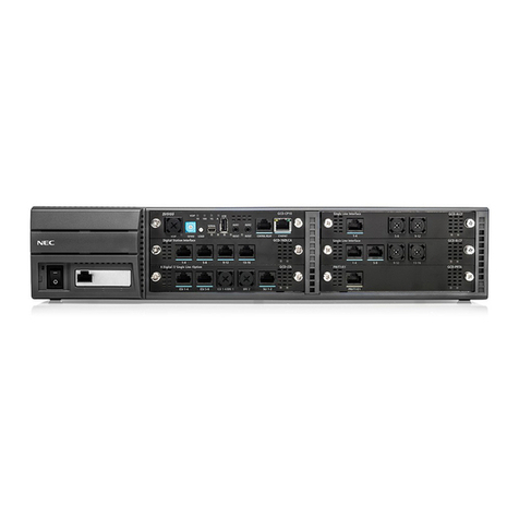
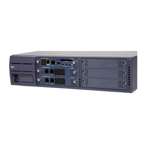
NEC NEAX 2400 ICS User manual

ND-70373 (E)
ISSUE 1
SN1433 CPRAF-A/SN1435 CPRAH-A
Installation Guide
JUNE, 1998
NEC America, Inc.
®

LIABILITY DISCLAIMER
NEC America, Inc. reserves the right to change the specifications,
functions, or features, at any time, without notice.
NEC America, Inc. has prepared this document for use by its em-
ployees and customers. The information contained herein is the
property of NEC America, Inc. and shall not be reproduced without
prior written approval from NEC America, Inc.
NEAX and Dterm are registered trademarks of NEC Corporation.
Copyright 1998
NEC America, Inc.
Printed in the U.S.A.

ND-70373 (E)
ISSUE 1
JUNE, 1998
SN1433 CPRAF-A/SN1435 CPRAH-A
Installation Guide
TABLE OF CONTENTS
Page
ND-70373 (E) TABLE OF CONTENTS
Page i
Revision 1.0
CHAPTER 1 GENERAL . . . . . . . . . . . . . . . . . . . . . . . . . . . . . . . . . . . . . . . . . . . . . . . . . . . . . . . . . . . . . . . . . . . 1
1. Outline . . . . . . . . . . . . . . . . . . . . . . . . . . . . . . . . . . . . . . . . . . . . . . . . . . . . . . . . . . . . . . . . . . . . . . . . . . . 1
2. Internal Cable Connection . . . . . . . . . . . . . . . . . . . . . . . . . . . . . . . . . . . . . . . . . . . . . . . . . . . . . . . . . . . 3
3. Switch Setting on CPU Board. . . . . . . . . . . . . . . . . . . . . . . . . . . . . . . . . . . . . . . . . . . . . . . . . . . . . . . . . 4
CHAPTER 2 INSTALLATION PROCEDURE . . . . . . . . . . . . . . . . . . . . . . . . . . . . . . . . . . . . . . . . . . . . . . . . . . . 5
1. Mounting of CPR . . . . . . . . . . . . . . . . . . . . . . . . . . . . . . . . . . . . . . . . . . . . . . . . . . . . . . . . . . . . . . . . . . . 5
2. Mounting of HFD . . . . . . . . . . . . . . . . . . . . . . . . . . . . . . . . . . . . . . . . . . . . . . . . . . . . . . . . . . . . . . . . . . . 6
3. Cable Connection for IMG
x
. . . . . . . . . . . . . . . . . . . . . . . . . . . . . . . . . . . . . . . . . . . . . . . . . . . . . . . . . . . 7
4. IMG
dxh
. . . . . . . . . . . . . . . . . . . . . . . . . . . . . . . . . . . . . . . . . . . . . . . . . . . . . . . . . . . . . . . . . . . . . . . . . . 10
4.1 Cable Connection . . . . . . . . . . . . . . . . . . . . . . . . . . . . . . . . . . . . . . . . . . . . . . . . . . . . . . . . . . . . 11
4.2 Mounting of Additional GATE (PZ-GT19) Card. . . . . . . . . . . . . . . . . . . . . . . . . . . . . . . . . . . . . 13
CHAPTER 3 SYSTEM STARTUP. . . . . . . . . . . . . . . . . . . . . . . . . . . . . . . . . . . . . . . . . . . . . . . . . . . . . . . . . . . 17
1. Program Installation . . . . . . . . . . . . . . . . . . . . . . . . . . . . . . . . . . . . . . . . . . . . . . . . . . . . . . . . . . . . . . . 19
1.1 Off-Line Startup. . . . . . . . . . . . . . . . . . . . . . . . . . . . . . . . . . . . . . . . . . . . . . . . . . . . . . . . . . . . . . 19
1.2 HD Initialization . . . . . . . . . . . . . . . . . . . . . . . . . . . . . . . . . . . . . . . . . . . . . . . . . . . . . . . . . . . . . . 20
1.3 Basic Software Installation. . . . . . . . . . . . . . . . . . . . . . . . . . . . . . . . . . . . . . . . . . . . . . . . . . . . . 21
1.4 Standard Service Software Installation. . . . . . . . . . . . . . . . . . . . . . . . . . . . . . . . . . . . . . . . . . . 22
1.5 Lamp Indication and System Message . . . . . . . . . . . . . . . . . . . . . . . . . . . . . . . . . . . . . . . . . . . 23

LIST OF FIGURES ND-70373 (E)
Page ii
Revision 1.0
LIST OF FIGURES
Figure Title Page
1-1 Outer View of CPR . . . . . . . . . . . . . . . . . . . . . . . . . . . . . . . . . . . . . . . . . . . . . . . . . . . . . . . . . . . . . . . 1
1-2 SN1433 CPRAF-A/SN1435 CPRAH-A . . . . . . . . . . . . . . . . . . . . . . . . . . . . . . . . . . . . . . . . . . . . . . . . 2
1-3 Internal Cable Connection . . . . . . . . . . . . . . . . . . . . . . . . . . . . . . . . . . . . . . . . . . . . . . . . . . . . . . . . 3
1-4 Jumper Switch Setting on CPU Board . . . . . . . . . . . . . . . . . . . . . . . . . . . . . . . . . . . . . . . . . . . . . . 4
2-1 Mounting of CPR . . . . . . . . . . . . . . . . . . . . . . . . . . . . . . . . . . . . . . . . . . . . . . . . . . . . . . . . . . . . . . . . 5
2-2 Mounting of HFD . . . . . . . . . . . . . . . . . . . . . . . . . . . . . . . . . . . . . . . . . . . . . . . . . . . . . . . . . . . . . . . . 6
2-3 Locations of Connectors (IMG
x
) . . . . . . . . . . . . . . . . . . . . . . . . . . . . . . . . . . . . . . . . . . . . . . . . . . . 7
2-4 Cable Connections for IMG
x
. . . . . . . . . . . . . . . . . . . . . . . . . . . . . . . . . . . . . . . . . . . . . . . . . . . . . . 8
2-5 Locations of Connectors (IMG
dxh
) . . . . . . . . . . . . . . . . . . . . . . . . . . . . . . . . . . . . . . . . . . . . . . . . 10
2-6 Cable Connections for IMG
dxh
. . . . . . . . . . . . . . . . . . . . . . . . . . . . . . . . . . . . . . . . . . . . . . . . . . . 11
2-7 Removal of CPR . . . . . . . . . . . . . . . . . . . . . . . . . . . . . . . . . . . . . . . . . . . . . . . . . . . . . . . . . . . . . . . . 13
2-8 Removal of CPR Cover . . . . . . . . . . . . . . . . . . . . . . . . . . . . . . . . . . . . . . . . . . . . . . . . . . . . . . . . . . 14
2-9 Removal of Slot Cover . . . . . . . . . . . . . . . . . . . . . . . . . . . . . . . . . . . . . . . . . . . . . . . . . . . . . . . . . . 15
2-10 Mounting of GATE Card . . . . . . . . . . . . . . . . . . . . . . . . . . . . . . . . . . . . . . . . . . . . . . . . . . . . . . . . . 16
3-1 EMA Card Mounting Location . . . . . . . . . . . . . . . . . . . . . . . . . . . . . . . . . . . . . . . . . . . . . . . . . . . . 17
3-2 Lamps and Switches on EMA Card Operation Panel . . . . . . . . . . . . . . . . . . . . . . . . . . . . . . . . . . 17
3-3 Operation Panel . . . . . . . . . . . . . . . . . . . . . . . . . . . . . . . . . . . . . . . . . . . . . . . . . . . . . . . . . . . . . . . . 18
3-4 OPE/ACT Lamp Indication . . . . . . . . . . . . . . . . . . . . . . . . . . . . . . . . . . . . . . . . . . . . . . . . . . . . . . . 24

ND-70373 (E) LIST OF TABLES
Page iii
Revision 1.0
LIST OF TABLES
Table Title Page
2-1 Cable Connections for IMG
x
. . . . . . . . . . . . . . . . . . . . . . . . . . . . . . . . . . . . . . . . . . . . . . . . . . . . . . . 9
2-2 Cable Connections for IMG
dxh
. . . . . . . . . . . . . . . . . . . . . . . . . . . . . . . . . . . . . . . . . . . . . . . . . . . . 12
3-1 Abnormal Lamp Indication on Line/Trunk Circuit Card . . . . . . . . . . . . . . . . . . . . . . . . . . . . . . . . 25

LIST OF TABLES ND-70373 (E)
Page iv
Revision 1.0
This page is for your notes.

ND-70373 (E) CHAPTER 1
Page 1
Revision 1.0
GENERAL
CHAPTER 1 GENERAL
1. Outline
The Central Processor Rack (CPR) is the system control block mounted in the Local Processor Rack (LPR). The
type of CPR differs depending on the system as listed below.
• SN1433 CPRAF-A : IMGx
• SN1435 CPRAH-A : IMGdxh
When two CPRs are mounted, redundant (dual) configuration of the system is available.
Outer view of each CPR is shown in Figure 1-1.
Figure 1-1 Outer View of CPR
SW
MBR
MB CPU OPE
HDD
FDD
ON
OFF
5A
I
O
ON
OFF
OUTPWR
INPWR
0123 4 56
WDT
GT0 GT1
GT2 GT3
ON
SYSTEM SELECT0 Note1
SW
MBR
MB CPU OPE
HDD
FDD
ON
OFF
5A
I
O
ON
OFF
OUTPWR
INPWR
012 3 45 6
WDT
GT0 GT1
GT2 GT3
ON
SYSTEM SELECT0 Note1
SN1433 CPRAF-A (IMGx)
SN1435 CPRAH-A (IMGdxh)

CHAPTER 1 ND-70373 (E)
Page 2
Revision 1.0
GENERAL
The CPR consists of the following components.
• PZ-PW92 : This card supplies operating power to the CPR and the circuit cards mounted in slots 00 to
04 of the LPR.
• PZ-IO27 : Floppy Disk Drive (FDD) and Hard Disk Drive (HDD) are mounted on this card.
• CPU Board : This card mainly contains Central Processing Unit (CPU), Random Access Memory (RAM),
Boot ROM, ISA Bus Controller and FDD/HDD Controller.
• PZ-GT17 : This card connects the CPU with the Local I/O Bus and Misc Bus, permitting the CPU to
directly control the INT/TSW, EMA, IOC and other miscellaneous circuit cards mounted in
IMG0.
• PZ-GT18 : This card connects the CPU with the Local I/O Bus, HSW I/O Bus and Misc Bus, permitting
the CPU to directly control the INT/TSW, HSW and other miscellaneous circuit cards
mounted in IMG1 and IMG2.
• PZ-GT19 : This card connects the CPU with the Local I/O Bus, HSW I/O Bus and Misc Bus, permitting
the CPU to directly control the INT/TSW, HSW and other miscellaneous circuit cards
mounted in IMG3.
Figure 1-2 SN1433 CPRAF-A/SN1435 CPRAH-A
SW
MBR
MB CPU OPE
HDD
FDD
ON
OFF
5A
I
O
ON
OFF
OUT PWR
IN PWR
012 3 45 6
WDT
GT0 GT1
GT2 GT3
ON
SYSTEM SELECT Note
PZ-PW92
Note 1 : Factory settings are as follows.
IMGx :
IMGxh/dxh :
PZ-IO27
PZ-GT18 (for IMG1/IMG2)
PZ-GT19 (for IMG3)
PZ-GT17(for IMG0)
AB AB
ON
SYSTEM SELECT
ON
SYSTEM SELECT
Front View
Note 2 : PZ-GT19 is for IMGdxh only.

ND-70373 (E) CHAPTER 1
Page 3
Revision 1.0
GENERAL
2. Internal Cable Connection
Internal cable connection of the CPR is shown in Figure 1-3.
Figure 1-3 Internal Cable Connection
Front View
PZ-PW92 KEY
(Above : LEDA)
(Below : LEDB) PZ-GT19
(for IMG3)
PZ-DK217
PZ-IO27
PWR GOOD
PZ-GT17(for IMG0)
CPU PZ-GT18
(for IMG1/IMG2)
FAN
FAN CA
FAN
(LED)
(LED)
(LEDA)
(LEDB)
2P INT CA-A
2P INT CA-A
(IDE1)
(FDD)
(DSPP)
30AL ST FLT CA
(BZ-M14 BWB)
DPWR IDEH FDFDD
FDD IF CA
HDD CABLE

CHAPTER 1 ND-70373 (E)
Page 4
Revision 1.0
GENERAL
3. Switch Setting on CPU Board
Factory setting of the jumper switches on the CPU board is shown in Figure 1-4.
Figure 1-4 Jumper Switch Setting on CPU Board
FREQ1
FREQ2
EP3
EP1
EP2
CLK1
CLK2
CPS
FAN
VR1
VR2

ND-70373 (E) CHAPTER 2
Page 5
Revision 1.0
INSTALLATION PROCEDURE
CHAPTER 2 INSTALLATION PROCEDURE
1. Mounting of CPR
When the system is to be in redundant (dual) configuration, mount the CPR for the system 1. When the system is 4-
IMG configuration, an additional GATE card must be mounted in the CPR (see 4.2 ).
Mount the CPR in the LPR and secure it with four screws as shown in Figure 2-1.
Figure 2-1 Mounting of CPR
SW
MBR
MB CPU OPE
HDD
FDD
ON
OFF
5A
I
O
ON
OFF
OUTPWR
INPWR
012 3 45 6
WDT
GT0 GT1
GT2 GT3
SW
MBR
MB CPU OPE
HDD
FDD
ON
OFF
5A
I
O
ON
OFF
OUTPWR
INPWR
012 3 45 6
WDT
GT0 GT1
GT2 GT3
ON
SYSTEM SELECT0 NOTE1
PBX
LPR
CPR

CHAPTER 2 ND-70373 (E)
Page 6
Revision 1.0
INSTALLATION PROCEDURE
2. Mounting of HFD
Mount the HFD in the CPR0. When the system is in redundant configuration, mount the HFD in the CPR1 in the
same manner. See Figure 2-2.
Figure 2-2 Mounting of HFD
SW
MBR
CPU OPE
ON
OFF
5A
I
O
ON
OFF
OUTPWR
INPWR
012 3 45 6
WDT
GT0 GT1
GT2 GT3
SW
MBR
CPU OPE
ON
OFF
5A
I
O
ON
OFF
OUTPWR
INPWR
012 3 45 6
WDT
GT0 GT1
GT2 GT3
PBX
LPR
HFD PKG

ND-70373 (E) CHAPTER 2
Page 7
Revision 1.0
INSTALLATION PROCEDURE
3. Cable Connection for IMG
x
CPR-related cable connectors are located at the front of the unit. See Figure 2-3.
Figure 2-3 Locations of Connectors (IMG
x
)
SW
MBR
MB CPU OPE
HDD
FDD
ON
OFF
5A
I
O
ON
OFF
OUT PWR
IN PWR
012 3 45 6
WDT
GT0 GT1
GT2 GT3
ON SYSTEM SELECT
PZ-IO27
PZ-PW92
LPR
00 01 02 03 04
PZ-GT17
PZ-IO27 PZ-GT17
CPR 1
CPR 0
SW
MBR
MB CPU OPE
HDD
FDD
ON
OFF
I
O
ON
OFF
OUT PWR
IN PWR
012 3 45 6
WDT
GT0 GT1
GT2 GT3
ON SYSTEM SELECT
PZ-PW92
E
M
A
M
I
S
C
M
I
S
C
M
I
S
C
I
O
C
AB
AB
5A

CHAPTER 2 ND-70373 (E)
Page 8
Revision 1.0
INSTALLATION PROCEDURE
Connect CPR-related cables as shown in Figure 2-4 and Table 2-1.
Figure 2-4 Cable Connections for IMG
x
BUS1A
PIM0
BZ-C10 PZ-PW92
BASEUPZ-M371
LPR
BUS0A
PA0
PB0
BUS0 BUS1
PALMPALM
CNA
CNB CNA
CNB
PALM1
PALM0
PWRB1
PWRB0
PZ-GT17 PZ-GT17
PWRA1
PWRA0
OUT
PWR
IN
PWR
OUT
PWR
IN
PWR
CPR1 LPR
PIM0
CPR0
BASEU
[1]
[7]
[2]
[3]
[4]
[5]
[6]
[9]
[10]
[8]
Rear View
IMG0 Front View
IMG0
[1]~[5] : For system 0
[6]~[10]: For system 1
PZ-PW92

ND-70373 (E) CHAPTER 2
Page 9
Revision 1.0
INSTALLATION PROCEDURE
Table 2-1 Cable Connections for IMG
x
[1]~[5] : For system 0
[6]~[10] : For system 1
NO.
CABLE CONNECTION
CABLE NAME REMARKS
FROM TO
MODULE
/UNIT CIRCUIT
CARD CONNECTOR MODULE
/UNIT CIRCUIT
CARD CONNECTOR
[1] SN1433 CPRAF-A
(Front) PZ-GT17 BUS CNB
(SLOT No.6) PIM0 - BUS0A 50-40 GT BUS
CA-A
[2] SN1433 CPRAF-A
(Front) PZ-GT17 BUS CNA
(SLOT No.6) LPR BZ-C10 BUS0 EXGT BUS CA-A
[3] SN1433 CPRAF-A
(Front) PZ-PW92 IN PWR BASEU PZ-M371 PA0 4P-2P PWR CA-A
[4] SN1433 CPRAF-A
(Front) PZ-PW92 OUT PWR LPR BZ-C10 PWRA0 6P-(4P-3P) PWR
CA-A
PWRB0
[5] SN1433 CPRAF-A
(Front) PZ-PW92 PALM LPR BZ-C10 PALM0 10AL-(110) FLT
CA
[6] SN1433 CPRAF-A
(Front) PZ-GT17 BUS CNB
(SLOT No.6) PIM0 - BUS1A 50-40 GT BUS
CA-A
[7] SN1433 CPRAF-A
(Front) PZ-GT17 BUS CNA
(SLOT No.6) LPR BZ-C10 BUS1 EXGT BUS CA-A
[8] SN1433 CPRAF-A
(Front) PZ-PW92 IN PWR BASEU PZ-M371 PB0 4P-2P PWR CA-B
[9] SN1433 CPRAF-A
(Front) PZ-PW92 OUT PWR LPR BZ-C10 PWRA1 6P-(4P-3P) PWR
CA-B
PWRB1
[10] SN1433 CPRAF-A
(Front) PZ-PW92 PALM LPR BZ-C10 PALM1 10AL-(130) FLT
CA

CHAPTER 2 ND-70373 (E)
Page 10
Revision 1.0
INSTALLATION PROCEDURE
4. IMG
dxh
CPR-related cable connectors are located at the front of the unit. See Figure 2-5.
Figure 2-5 Locations of Connectors (IMG
dxh
)
SW
MBR
MB CPU OPE
HDD
FDD
ON
OFF
I
O
ON
OFF
OUT PWR
IN PWR
012 3 45 6
WDT
GT0 GT1
GT2 GT3
ON SYSTEM SELECT
PZ-IO27
PZ-PW92
LPR
00 01 02 03 04
PZ-GT17
PZ-GT18
PZ-IO27 PZ-GT18
CPR 1
CPR 0
SW
MBR
MB CPU OPE
HDD
FDD
ON
OFF
5A
I
O
ON
OFF
OUT PWR
IN PWR
012 3 45 6
WDT
GT0 GT1
GT2 GT3
ON SYSTEM SELECT
PZ-PW92
PZ-GT19 Note
Note : This GATE (PZ-GT19) card is used for IMG3.
PZ-GT19 Note
PZ-GT17
E
M
A
M
I
S
C
M
I
S
C
M
I
S
C
I
O
C
ABAB
ABAB
5A

ND-70373 (E) CHAPTER 2
Page 11
Revision 1.0
INSTALLATION PROCEDURE
4.1 Cable Connection
Connect CPR-related cables as shown in Figure 2-6 and Table 2-2.
Figure 2-6 Cable Connections for IMGdxh
BUS1A BUS0A
PIM0PIM0 PIM0
HSWM BZ-C10
PZ-PW92
PZ-PW92
BASEUBASEU
HSWM
BASEU
HSWM
BASEU
PZ-M371
PA0
PB0
BUS0 BUS1
IOP1IOP0
IOP1IOP0 IOP1IOP0
PALM0 PALM
PALM1
PALM0 PWRB1
PWRB0 PWRA1
PWRA0
PZ-GT18PZ-GT18
CNA
CNB
CNA
CNB
PZ-GT17
PZ-GT19
CNA
CNB
CNA
CNB
PZ-GT17
PZ-GT19
IN
PWR OUT
PWR IN
PWR OUT
PWR
CPR1
CPR0
BASEU
[13]
[1]
[7]
[2]
[3]
[4]
[5]
[6]
[9]
[8]
[10]
[11]
[12]
[14]
[16]
[16][15]
[7]
[15]
[8]
(Front View)
IMG3
(Front View)
IMG2 (Front View)
IMG1
(Front View)
IMG0
(Rear View)
IMG0
[1]~[8]: For system 0 [9]~[16]: For system 1
CN
CN
Note
Note
D
B
C
A
A
B
C
D
Note : Connect these cables referring to the table below.
LPR Label on the Cable Corresponding GATE Card
CPR 0
CPU0. SLOT1/3 or CPU0. SLOT1/3/5B PZ-GT18 (CNB)
CPU0. SLOT2 or CPU0. SLOT2/5A PZ-GT18 (CNA)
CPU0. SLOT3 or CPU0. SLOT3/4 PZ-GT19
CPR 1
CPU1. SLOT1/3 or CPU1. SLOT1/3/5B PZ-GT18 (CNB)
CPU1. SLOT2 or CPU1. SLOT2/5A PZ-GT18 (CNA)
CPU1. SLOT3 or CPU1. SLOT3/4 PZ-GT19

CHAPTER 2 ND-70373 (E)
Page 12
Revision 1.0
INSTALLATION PROCEDURE
Table 2-2 Cable Connections for IMGdxh
Note: See Note on Figure 2-6. [1]~[8] : For system 0
[9]~[16]: For system 1
NO.
CABLE CONNECTION
CABLE NAME REMARKS
FROM TO
MODULE
/UNIT CIRCUIT
CARD CONNECTOR MODULE
/UNIT CIRCUIT
CARD CONNECTOR
[1] SN1435 CPRAH-A
(Front) PZ-GT17 BUS CNB
(SLOT No.6) PIM0 - BUS0A 50-40 GT BUS CA-A
[2] SN1435 CPRAH-A
(Front) PZ-GT17 BUS CNA
(SLOT No.6) LPR BZ-C10 BUS0 EXGT BUS CA-A
[3] SN1435 CPRAH-A
(Front) PZ-PW92 IN PWR BASEU PZ-
M371 PA0 4P-2P PWR CA-A
[4] SN1435 CPRAH-A
(Front) PZ-PW92 OUT PWR LPR BZ-C10 PWRA0 6P-(4P-3P) PWR
CA-A
PWRB0
[5] SN1435 CPRAH-A
(Front) PZ-PW92 PALM LPR BZ-C10 PALM0 10AL-(110) FLT CA
[6] SN1435 CPRAH-A
(Front) PZ-GT18 BUS CNB
(SLOT No.5) IMG1
HSWM - IOP0 68PH 50AL CA-B Note
[7] SN1435 CPRAH-A
(Front) PZ-GT18 BUS CNA
(SLOT No.5) IMG2
HSWM - IOP0 68PH 50AL CA-B Note
[8] SN1435 CPRAH-A
(Front) PZ-GT19 BUS
(SLOT No.4) IMG3
HSWM - IOP0 68PH 50AL CA-C Note
[9] SN1435 CPRAH-A
(Front) PZ-GT17 BUS CNB
(SLOT No.6) PIM0 - BUS1A 50-40 GT BUS CA-A
[10] SN1435 CPRAH-A
(Front) PZ-GT17 BUS CNA
(SLOT No.6) PIM0 BZ-C10 BUS1 EXGT BUS CA-A
[11] SN1435 CPRAH-A
(Front) PZ-PW92 IN PWR BASEU PZ-M371 PB0 4P-2P PWR CA-B
[12] SN1435 CPRAH-A
(Front) PZ-PW92 OUT PWR LPR BZ-C10 PWRA1 6P-(4P-3P) PWR
CA-B
PWRB1
[13] SN1435 CPRAH-A
(Front) PZ-PW92 PALM LPR BZ-C10 PALM1 10AL-(130) FLT CA
[14] SN1435 CPRAH-A
(Front) PZ-GT18 BUS CNB
(SLOT No.5) IMG1
HSWM - IOP1 68PH 50AL CA-A Note
[15] SN1435 CPRAH-A
(Front) PZ-GT18 BUS CNA
(SLOT No.5) IMG2
HSWM - IOP1 68PH 50AL CA-B Note
[16] SN1435 CPRAH-A
(Front) PZ-GT19 BUS
(SLOT No.4) IMG3
HSWM - IOP1 68PH 50AL CA-C Note

ND-70373 (E) CHAPTER 2
Page 13
Revision 1.0
INSTALLATION PROCEDURE
4.2 Mounting of Additional GATE (PZ-GT19) Card
When the system is 4-IMG configuration, an additional GATE card must be mounted in the CPR. This sec-
tion explains the procedure for mounting the additional GATE card.
(1) Removal of CPR
Remove the CPR0 from the LPR as shown in Figure 2-7.
Figure 2-7 Removal of CPR
SW
MBR
CPU OPE
ON
OFF
5A
I
O
ON
OFF
OUTPWR
INPWR
012 3 45 6
WDT
GT0 GT1
GT2 GT3
ON
SYSTEM SELECT0(Note1)
PBX
LPR

CHAPTER 2 ND-70373 (E)
Page 14
Revision 1.0
INSTALLATION PROCEDURE
(2) Removal of CPR Cover
Remove the front cover (right side only) and the top cover as shown in Figure 2-8.
Figure 2-8 Removal of CPR Cover
GT0
MBR
GT2
WDT
GT1
GT3
CPUOPE
SYSTEM SELECT
ON
ON
OFF
12
3456
0
SW ON
OFF
5A
MB
HDD
FDD
OUT PWR
IN PWR
ON
OFF
Other manuals for NEAX 2400 ICS
2
This manual suits for next models
2
Table of contents
Other NEC PBX manuals

NEC
NEC Univerge SV9300 User manual

NEC
NEC NEAX 2400 IPX Owner's manual

NEC
NEC SL1000 Owner's manual

NEC
NEC SL1000 Owner's manual

NEC
NEC ASPILA EX User manual

NEC
NEC DS2000 IntraMail User manual

NEC
NEC SV8300 Installation instructions

NEC
NEC Univerge SV8100 User manual

NEC
NEC UX5000 User manual

NEC
NEC SV8300 User manual
Popular PBX manuals by other brands

Panasonic
Panasonic HYBRID IP-PBX KX-TDA100 installation manual

LG-Ericsson
LG-Ericsson iPECS SBG-1000 quick start guide

Matrix
Matrix ETERNITY NE quick start

TransTel Communications
TransTel Communications IP8100C user manual

Nortel
Nortel Meridian Companion Product support bulletin

Auerswald
Auerswald COMpact 4000 Operation guide