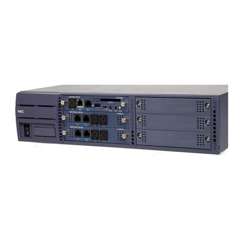
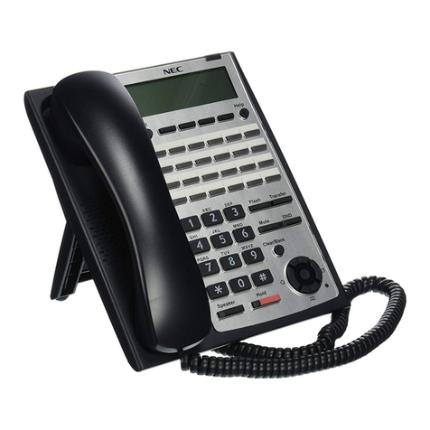
NEC ASPILA EX User manual

Hardware Manual
00.24
5. Data and SMDR
1. Installing Cabinets
3. Installing Extensions
and Trunks
4. Optional Equipment
2. PCB Installation and
Startup
6. LAN Connection
7. Specifications and
Parts
CÔNG TY VIỄN THÔNG VIỆT PRO
Chuyên phân phối tổng đài NEC
http://vietpro.com.vn

This manual has been developed by NEC Infrontia Asia Pacific Sdn. Bhd. It is intended for the use of its customers
and service personnel, and should be read in its entirety before attempting to install or program the system. Any
comments or suggestions for improving this manual would be appreciated. Forward your remarks to:
NEC Infrontia Asia Pacific Sdn. Bhd.
24, Jalan Juruhebah U1/50,
Temasya Industrial Park Phase 2,
Seksyen U1 Glenmarie,
40150 Shah Alam,
Selangor Darul Ehsan, Malaysia.
www.necinfrontia-ap.com
Nothing contained in this manual shall be deemed to be, and this manual does not constitute, a warranty of, or
representation with respect to, any of the equipment covered. This manual is subject to change without notice and
NEC Infrontia has no obligation to provide any updates or corrections to this manual. Further, NEC Infrontia also
reserves the right, without prior notice, to make changes in equipment design or components as it deems
appropriate. No representation is made that this manual is complete or accurate in all respects and NEC Infrontia
shall not be liable for any errors or omissions. In no event shall NEC Infrontia be liable for any incidental or
consequential damages in connection with the use of this manual. This document contains proprietary information
that is protected by copyright. All rights are reserved. No part of this document may be photocopied or reproduced
without prior written consent of NEC Infrontia
©2003 by NEC Infrontia Asia Pacific Sdn. Bhd.
CÔNG TY VIỄN THÔNG VIỆT PRO
Chuyên phân phối tổng đài NEC
http://vietpro.com.vn

Table of Contents
Aspila EX Hardware Manual Table of Contents i
Table of Contents
Section 1:
Installing the Main and Expansion Cabinets1-1
GENERAL PRECAUTIONS1-1
GETTING STARTED1-2
Additional parts supplied with the Aspila EX1-2
INSTALLING THE MAIN CABINET1-3
Unpacking1-3
Before Installing1-3
Site Requirements1-3
Environmental Requirements1-3
Removing the Front Cover (Figure 1-1)1-4
Removing the Side Panels (Figure 1-2)1-5
Securing the Main Cabinet to the Floor (Figure 1-3 - Figure 1-7)1-6
Securing the Main Cabinet to the Wall (Figure 1-8 - Figure 1-12)1-10
Securing the Main Cabinet to a Rack (Figure 1-13 - Figure 1-17)1-13
INSTALLING AN EXPANSION CABINET1-18
Expansion Cabinet1-18
Before Installing an Expansion Cabinet1-18
Expanding a Floor System (Figure 1-18 - Figure 1-26)1-18
Expanding a Rack Mounted System (Figure 1-27 - Figure 1-34)1-25
REPLACING THE POWER SUPPLY1-31
Power Supplies in the Main and Expansion Cabinets1-31
GROUNDING THE CABINETS1-32
Connecting the System Ground (Figure 1-35)1-32
COMPLETING THE INSTALLATION1-34
Reinstalling the Front Cover (Figure 1-36)1-34
Section 2:
PCB Installation and Startup2-1
PCB LAYOUT2-1
PCB Location2-1
Order of Installing Extension PCBs2-2
Order of Installing Trunk PCBs2-2
PCB INSTALLATION2-3
Handling the PCBs2-3
"Busying Out" Extension/Line PCBs2-3
Installing an Extension or Trunk PCB (Figure 2-1, Figure 2-2)2-3
Removing an Extension or Trunk PCB2-4
Uninstalling a PCB Slot Through Software2-4
Where to Install the PCBs2-5
Central Processing Unit (NTCPU) PCB (Figure 2-3)2-6
Connector Pin-Outs on NTCPU2-10
Expansion (EXIFU) PCB (Figure 2-5)2-14
DSPDB Daughter Board (Figure 2-6, Figure 2-7)2-15
Digital Station (8/16ESIU) PCB (Figure 2-8)2-17
Analogue Station (8SLIU) PCB (Figure 2-9)2-19
Analogue Station (8SLIDB) Daughter Board (Figure 2-10 - Figure 2-11)2-21
Analogue Trunk (4/8COIU) PCB (Figure 2-12)2-23
Direct Inward Dial (DID) (4/8DIOPU) PCB (Figure 2-13)2-26
Tie Line (4TLIU) PCB (Figure 2-14)2-28
CÔNG TY VIỄN THÔNG VIỆT PRO
Chuyên phân phối tổng đài NEC
http://vietpro.com.vn

Table of Contents
ii Table of Contents Aspila EX Hardware
BRI (2/4/8BRIU) Interface PCB (Figure 2-15)2-34
PRI (1PRIU) Interface PCB (Figure 2-16)2-37
In-Skin Server/Router (APSU) PCB (Figure 2-17)2-40
LAN 8-Port Switching Hub (8SHUBU) PCB (Figure 2-18)2-43
VoIP (16VOIPU) PCB (Figure 2-19)2-45
VoIP (VOIPDB) Daughter Board (Figure 2-20 - Figure 2-21)2-47
PCB STARTUP2-48
Initial PCB Installation2-48
Initial Installation of Trunk PCBs2-49
SYSTEM STARTUP2-50
System Startup2-50
Powering up the System2-50
Initial Programming (Figure 2-22)2-51
Setting Up Extension Circuit Types2-52
Saving Your Configuration2-52
Upgrading Your Software2-52
Making Test Calls2-53
Basic Troubleshooting2-54
Identifying Port Location2-55
SYSTEM SHUTDOWN2-56
Powering Off the System2-56
Resetting the System (Hot Start)2-56
Section 3:
Installing Extensions and Trunks3-1
RJ61 WIRING AND PINOUTS3-2
INSTALLING EXTENSIONS3-3
Digital Extension Cabling3-3
Installing a Key Telephone3-3
INSTALLING SINGLE LINE TELEPHONES3-4
Single Line Extension Cabling3-4
Installing a Single Line Telephone3-4
INSTALLING CO/PBX LINES3-5
Ground Start/Loop Start Line Cabling3-5
Installing Ground Start/Loop Start Lines3-5
INSTALLING BRI TRUNKS3-6
BRI Trunks3-6
INSTALLING PRI TRUNKS3-7
PRI Trunks3-7
INSTALLING DID TRUNKS3-8
DID Trunks3-8
INSTALLING TIE LINES3-9
Tie Line: 4TLIU3-9
TESTING TELEPHONE OPERATION3-11
SUPER DISPLAY LCD3-12
Positioning the Super Display LCD(Figure 3-3, Figure 3-4)3-12
Section 4:
Optional Equipment4-1
2PGDAD MODULE4-1
Using a 2PGDAD Module (Figure 4-1 - Figure 4-8)4-1
LED Indications4-2
Setting Up 2PGDAD Module Connections4-2
BACKGROUND MUSIC4-6
Installing Background Music (Figure 4-9)4-6
DOOR BOX4-7
CÔNG TY VIỄN THÔNG VIỆT PRO
Chuyên phân phối tổng đài NEC
http://vietpro.com.vn

Table of Contents
Aspila EX Hardware Manual Table of Contents iii
Installing a Door Box (Figure 4-10, Figure 4-11)4-7
DSS CONSOLE4-10
Using a DSS Console (Figure 4-12 - Figure 4-13)4-10
EXTERNAL PAGING4-13
External Page (Figure 4-14, Figure 4-15)4-13
EXTERNAL PAGING AND PAGE RELAYS4-15
External Page Relays4-15
Door Box /External Page Relay Contacts (Figure 4-15)4-15
HEADSETS4-16
Connecting a Headset4-16
SYSTEM PHONE LABELING4-17
Labeling Your Phone4-17
MUSIC SOURCES4-18
Music on Hold (Figure 4-16, Figure 4-17)4-18
NIGHT MODE SELECTION4-20
Night Mode Selector Switch4-20
OPTIONAL PHONE ADAPTERS4-21
Using Adapters (Figure 4-18)4-21
Removing the Adapter Cover (Figure 4-19)4-22
ADA Adapter (Figure 4-20 - Figure 4-26)4-23
APA and APR Adapters (Figure 4-27 - Figure 4-28)4-26
CTA Adapter (Figure 4-27 - Figure 4-28)4-28
CTU Adapter (Figure 4-31 - Figure 4-32)4-29
VoIP Adapter (Figure 4-33 - Figure 4-35)4-30
POWER FAILURE TELEPHONES4-32
Power Failure (Figure 4-36)4-32
SLT ADAPTER4-34
Using the SLT Adapter (Figure 4-37 - Figure 4-38)4-34
TELEPHONE LEGS4-36
Using the Telephone Legs (Figure 4-39 - Figure 4-43)4-36
Adjusting the Leg Height4-36
WALL-MOUNT BRACKET4-39
Using the Wall-Mount Bracket4-39
Installing the Wall-Mount Handset Bracket (Figure 4-44 - Figure 4-46)4-39
Wall-Mounting the Phone (Figure 4-50 - Figure 4-50)4-40
Removing the Phone From a Wall-Mounting Bracket (Figure 4-51 - Figure 4-52)
4-44
Section 5:
Data and SMDR5-1
DATA OVERVIEW5-1
Data Communications5-1
Data Communication Availability With Hardware5-2
Ports for APR Adapter5-3
Programming for System and Alarm Reports5-3
SMDR5-4
Using SMDR (Figure 5-1)5-4
Programming SMDR5-5
Section 6:
LAN Connection6-1
LAN DEVICES6-1
CÔNG TY VIỄN THÔNG VIỆT PRO
Chuyên phân phối tổng đài NEC
http://vietpro.com.vn

Table of Contents
iv Table of Contents Aspila EX Hardware
Using LANs6-1
Installing a LAN Device or VoIP Telephone6-6
Section 7:
Specifications and Parts List7-1
SYSTEM SPECIFICATIONS7-1
PARTS LIST7-8
CÔNG TY VIỄN THÔNG VIỆT PRO
Chuyên phân phối tổng đài NEC
http://vietpro.com.vn

Section 1: Installing the Cabinets
Aspila EX Hardware Manual Section 1: Installing the Cabinets 1-1
1
Section 1:
Installing the Cabinets
Section 1: Installing the Cabinets
Section 1:
Installing the Main and
Expansion Cabinets
GENERAL PRECAUTIONS
•To avoid shock or equipment damage, do not plug in or turn the system power on before complet-
ing the installation process.
•Avoid working with the equipment during electrical storms.
•Use only commercial AC power to prevent shock or fire.
•Use the power cord supplied for the cabinet.
•Do not bundle AC power cords together, the cords may overheat.
•Make sure the cabinet has a proper Earth ground.
•Install batteries with the correct polarity to prevent damaging equipment.
•The cabinet should not be placed on unstable surfaces.
CÔNG TY VIỄN THÔNG VIỆT PRO
Chuyên phân phối tổng đài NEC
http://vietpro.com.vn

Section 1: Installing the Cabinets
1-2 Section 1: Installing the Cabinets Aspila EX Hardware
GETTING STARTED
Additional parts supplied with the Aspila EX
Technical CD
The Aspila EX Technical CD contains all the manuals required to install the Aspila EX system.
•Aspila EX Hardware Manual
How to install the parts of the Aspila EX system includes how to make connection to all ports
within the system.
•Aspila EX Software Manual
Explains the operation for all features on the system.
•Aspila EX Programming Manual
How to configure the Aspila EX system.
System Phone Label Maker
Software that allows the installer to customise the button designation for System Phones. There is
a standard inlay already fitted to the system phones. Label Maker allows this inlay to be replaced
with the button configuration setup by the installer.
Declaration of Conformity
This is a regulatory document that must be passed to the customer. The documant explains the
R&TTE standards to which the Aspila EX system is approved.
CÔNG TY VIỄN THÔNG VIỆT PRO
Chuyên phân phối tổng đài NEC
http://vietpro.com.vn

Section 1: Installing the Cabinets
Aspila EX Hardware Manual Section 1: Installing the Cabinets 1-3
1
INSTALLING THE MAIN CABINET
Unpacking
Unpack the equipment and check it against your equipment lists. Inspect for physical damage. If you
are not sure about a component’s function, review the information for the component within this man-
ual. Contact your Sales Representative if you have additional questions.
Make sure you have appropriate tools for the job, including: a test set, a punch down tool, and a digital
voltmeter.
Before Installing
Make sure you have a building plan showing common equipment, extensions, the telecom demarca-
tion, and earth ground location. The installation site must meet the Enviromental Requirements.
Site Requirements
The system can be floor-mounted, wall mounted, or rack mounted. Each cabinet is supplied with a
bracket which can be used to secure the cabinet in floor or wall mounting, for rack mounting the
bracket supplied can be used only if there are rear mounting strips within the rack cabinet, if not a sep-
erate bracket can be used. Ensure that enough space is available to allow the installation of an expan-
sion cabinet above the Main Cabinet.
The system requires a three-prong dedicated 200-240 VAC 50 Hz circuit located within 2.0 metres of
the AC receptacle.
The cabinet is shipped fully assembled. The following is enclosed with the cabinet:
•1 power cord with IEC 320/CEE 22 Angled socket (packed outside the cabinet)
•1 mounting bracket for floor or wall mounting (can be used for rack mounting where possible see
Securing the Main Cabinet to a Rack (Figure 1-13 - Figure 1-17) packed outside the cabinet
Environmental Requirements
Meeting and maintaining established environmental standards maximizes the life of the system. Be
sure that the site selected for the cabinet is not:
1. In direct sunlight or in hot, cold, or humid places.
2. In dusty areas or in areas where sulfuric gases are produced.
3. In places where shocks or vibrations are frequent or strong.
4. In places where water or oil comes in contact with the unit.
5. In areas near high-frequency machines or electric welders.
6. Near computers, telexes, microwaves, air conditioners, etc.
7. Near radio antennas (including shortwave).
CÔNG TY VIỄN THÔNG VIỆT PRO
Chuyên phân phối tổng đài NEC
http://vietpro.com.vn

Section 1: Installing the Cabinets
1-4 Section 1: Installing the Cabinets Aspila EX Hardware
Removing the Front Cover (Figure 1-1)
1. Position the cabinet on the floor near the MDF within 2 metres of the dedicated AC outlet.
(Do not secure the cabinet to the wall at this time).
2. Loosen two front panel retaining screws.
3. Slide the front cover to the right then pull straight out.
Figure 1-1: REMOVING THE FRONT COVER
Step 1
Step 2
Step 3
CÔNG TY VIỄN THÔNG VIỆT PRO
Chuyên phân phối tổng đài NEC
http://vietpro.com.vn

Section 1: Installing the Cabinets
Aspila EX Hardware Manual Section 1: Installing the Cabinets 1-5
1
Removing the Side Panels (Figure 1-2)
1. Loosen the side panel retaining screws located on the front of the cabinet. Remove the side
panel covers of the Main Cabinet by pulling out slightly then moving it towards the back of
the cabinet to unhook the panel.
Figure 1-2: REMOVING THE SIDE PANELS
Step 1
Step 2
CÔNG TY VIỄN THÔNG VIỆT PRO
Chuyên phân phối tổng đài NEC
http://vietpro.com.vn

Section 1: Installing the Cabinets
1-6 Section 1: Installing the Cabinets Aspila EX Hardware
Securing the Main Cabinet to the Floor (Figure 1-3 - Figure 1-7)
1. Install the wall bracket on the floor providing the appropriate spacing as shown below.
Figure 1-3: INSTALLING THE MOUNTING BRACKET
2. Secure the mounting bracket to the floor using four 6mm anchor bolts.
Figure 1-4: SECURE THE MOUNTING BRACKET WITH THE SCREWS
CÔNG TY VIỄN THÔNG VIỆT PRO
Chuyên phân phối tổng đài NEC
http://vietpro.com.vn

Section 1: Installing the Cabinets
Aspila EX Hardware Manual Section 1: Installing the Cabinets 1-7
1
3. Remove the 2 screws from the front of the mounting bracket.
Figure 1-5: REMOVE THE SCREWS FROM THE MOUNTING BRACKET
CÔNG TY VIỄN THÔNG VIỆT PRO
Chuyên phân phối tổng đài NEC
http://vietpro.com.vn

Section 1: Installing the Cabinets
1-8 Section 1: Installing the Cabinets Aspila EX Hardware
4. Place the cabinet on the secured mounting bracket and slide backwards.
Figure 1-6: ATTACHING THE CABINET TO THE MOUNTING BRACKET
CÔNG TY VIỄN THÔNG VIỆT PRO
Chuyên phân phối tổng đài NEC
http://vietpro.com.vn

Section 1: Installing the Cabinets
Aspila EX Hardware Manual Section 1: Installing the Cabinets 1-9
1
5. Secure the cabinet to the mounting bracket by reinstalling the two screws removed from the
mounting bracket in step 2.
Figure 1-7: REINSTALL SCREWS
CÔNG TY VIỄN THÔNG VIỆT PRO
Chuyên phân phối tổng đài NEC
http://vietpro.com.vn

Section 1: Installing the Cabinets
1-10 Section 1: Installing the Cabinets Aspila EX Hardware
Securing the Main Cabinet to the Wall (Figure 1-8 - Figure 1-12)
1. Install the wall bracket to the wall providing the appropriate spacing as shown below. The two
top key-hole screws should protrude from the wall about 3mm to allow the bracket to slide
over the screw heads.
It is suggested that plywood first be installed on the wall where the cabinet will be posi-
tioned. This allows for secure anchoring of the screws which will be supporting the weight of
the cabinet.
Note: Only one cabinet should be wall mounted. Two cabinets may result in too much
weight to be safely mounted together. The weight of a two cabinet system can be up to 50kg.
Figure 1-8: INSTALLING THE MOUNTING BRACKET
CÔNG TY VIỄN THÔNG VIỆT PRO
Chuyên phân phối tổng đài NEC
http://vietpro.com.vn

Section 1: Installing the Cabinets
Aspila EX Hardware Manual Section 1: Installing the Cabinets 1-
1
2. Remove the two screws from the back of the cabinet.
Figure 1-9: REMOVE THE SCREWS FROM THE CABINET
3. Hook the mounting bracket onto the back of the cabinet.
Figure 1-10: ATTACH BRACKET TO THE CABINET
4. Replace the two screws removed in step 2 to secure the bracket to the cabinet.
5. Plug the power cord into the back of the cabinet.
Due to the spacing between the cabinet and the wall, this cannot be done once the cabi-
net is fixed to the wall.
CÔNG TY VIỄN THÔNG VIỆT PRO
Chuyên phân phối tổng đài NEC
http://vietpro.com.vn

Section 1: Installing the Cabinets
1-12 Section 1: Installing the Cabinets Aspila EX Hardware
6. Lift the cabinet into position and slide the mounting bracket over the screws attached to the
wall.
Figure 1-11: ATTACHING THE CABINET TO THE MOUNTING BRACKET
7. Secure the cabinet to the wall by inserting the two screws into the bottom half of the mounting
bracket.
Figure 1-12: FASTEN BRACKET TO WALL
CÔNG TY VIỄN THÔNG VIỆT PRO
Chuyên phân phối tổng đài NEC
http://vietpro.com.vn

Section 1: Installing the Cabinets
Aspila EX Hardware Manual Section 1: Installing the Cabinets 1-
1
Securing the Main Cabinet to a Rack (Figure 1-13 - Figure 1-17)
1. Install the 19” rack mount bracket. The 19” rack mount bracket is not supplied with the cabi-
net and must be ordered seperately.
The cabinet will require approximately 400mm (9U) of height within the rack.
Figure 1-13: INSTALLING THE MOUNTING BRACKET ON THE RACK
Note that the floor/wall mounting bracket supplied with each cabinet can be used for rack
mouning ONLY IF the rack enclosure has the mounting strips at the rear. The mounting
bracket is installed onto the rear mounting strips and the instructions for Securing the Main
Cabinet to the Wall (Figure 1-8 - Figure 1-12) are followed to install the cabinet(s)
CÔNG TY VIỄN THÔNG VIỆT PRO
Chuyên phân phối tổng đài NEC
http://vietpro.com.vn

Section 1: Installing the Cabinets
1-14 Section 1: Installing the Cabinets Aspila EX Hardware
2. Remove the two screws from the front of the rack mount bracket.
Figure 1-14: REMOVE THE SCREWS FROM THE RACK
CÔNG TY VIỄN THÔNG VIỆT PRO
Chuyên phân phối tổng đài NEC
http://vietpro.com.vn
Other manuals for ASPILA EX
3
Table of contents
Other NEC PBX manuals

NEC
NEC SV8300 User manual

NEC
NEC NEAX 2400 ICS User manual

NEC
NEC Univerge SV9100 Quick start guide

NEC
NEC Univerge SV9100 User manual

NEC
NEC ELECTRA ELITE IPK II Owner's manual

NEC
NEC Univerge SV9300 User manual

NEC
NEC SV8300 Installation instructions

NEC
NEC NEAX 2400 IPX Owner's manual

NEC
NEC XN120 2OPBOX User manual

NEC
NEC UX5000 User manual
Popular PBX manuals by other brands

Panasonic
Panasonic KX-TDA30 user manual

Panasonic
Panasonic DBS Series Programming manual

Philips
Philips SOPHO Call@Net manual

Mitel
Mitel Navigator 3300 ICP Hardware technical reference manual

ZyXEL Communications
ZyXEL Communications X6004 user guide

Grandstream Networks
Grandstream Networks DP715 user guide