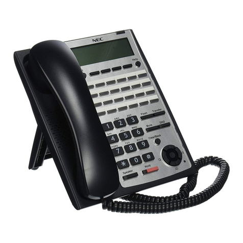
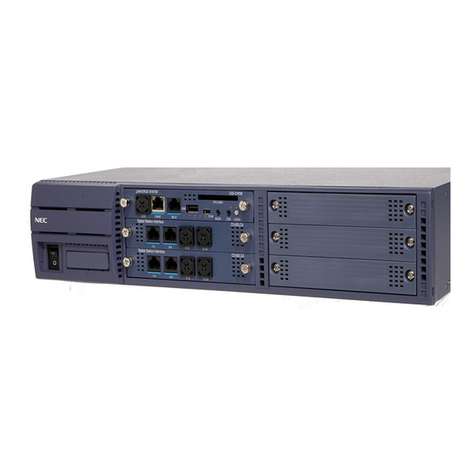
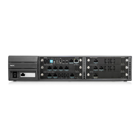
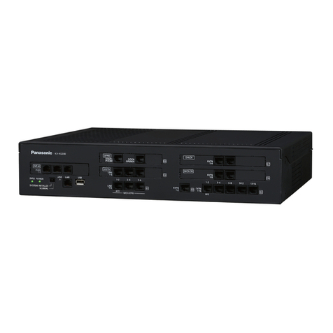
NEC Univerge SV9300 User manual

Networking Manual
NWA-088654-001
ISSUE 1.0

LIABILITY DISCLAIMER
NEC Corporation reserves the right to change the specifications,
functions, or features, at any time, without notice.
NEC Corporation has prepared this document for use by its employ-
ees and customers. The information contained herein is the property
of NEC Corporation and shall not be reproduced without prior written
approval from NEC Corporation.
Dterm is a registered trademark of NEC Corporation.
PCPro is a trademark of NEC Corporation.
Copyright 2014
NEC Corporation

i NWA-088654-001 Rev.1.0
94toc001.fm
TABLE OF CONTENTS
INTRODUCTION
PURPOSE ................................................................................................................ 1
OUTLINE OF THIS MANUAL ................................................................................... 2
TERMS IN THIS MANUAL ....................................................................................... 3
PBX System Designation ................................................................................................. 3
Attendant Console Name ................................................................................................. 3
Terminal Name ................................................................................................................ 4
REFERENCE MANUAL ........................................................................................... 5
HOW TO READ THIS MANUAL ............................................................................... 6
PRECAUTIONS ........................................................................................................ 7
System Data Backup ....................................................................................................... 7
Chapter 1 CCIS FEATURES
SYSTEM OUTLINE .................................................................................................. 1-2
PLO .................................................................................................................................. 1-3
No. 7 CCIS ....................................................................................................................... 1-4
Centralized Billing ............................................................................................................ 1-5
Inter-Office Digital Data Transmission through No. 7 CCIS ............................................. 1-7
TIME SLOT ASSIGNMENT CONDITION ................................................................. 1-8
Time Slot Allocation for CCT Blade ................................................................................. 1-8
Number of Time Slots Required for CCT Blade ............................................................... 1-9
CCT SPECIFICATIONS ........................................................................................... 1-10
Transmission Characteristics ........................................................................................... 1-10
Frame Configuration of 24CCT ........................................................................................ 1-11
Frame Configuration of 30CCT ........................................................................................ 1-15
MODEM Specifications .................................................................................................... 1-16
SERVICES ............................................................................................................... 1-17
NETWORK STRUCTURE CONSIDERATIONS ....................................................... 1-20
Determining System Configuration .................................................................................. 1-20
Determining Number of No. 7 CCIS Routes .................................................................... 1-20
Determining Type of Transmission Lines ........................................................................ 1-20
Determining Which PBX Should Be Main Office ............................................................. 1-21
Determining Point Code ................................................................................................... 1-22
Determining CCH Link to Send Messages ...................................................................... 1-24
Determining Numbering Plan ........................................................................................... 1-26

ii NWA-088654-001 Rev.1.0
94toc001.fm
Determining Route Advance ............................................................................................ 1-33
Network Construction with 2400 IPX ............................................................................... 1-36
CCIS BASIC PROGRAMMING ................................................................................ 1-37
Digital Trunk Data Assignment ........................................................................................ 1-38
Numbering Plan Assignment ........................................................................................... 1-46
Inter-Tenant Connection Assignment .............................................................................. 1-51
Sample Data Programming for Open Numbering System ............................................... 1-54
Sample Data Programming for Closed Numbering System ............................................ 1-59
Route Advance Assignment ............................................................................................ 1-64
CCIS FEATURE PROGRAMMING .......................................................................... 1-68
ATTENDANT CAMP-ON WITH TONE INDICATION-CCIS ................................. 1-69
AUTOMATIC RECALL-CCIS ............................................................................... 1-71
BROKERAGE-HOT LINE-CCIS ........................................................................... 1-72
BUSY LAMP FIELD (BLF)-CCIS .......................................................................... 1-75
BUSY VERIFICATION-CCIS ................................................................................ 1-80
CALL BACK-CCIS ................................................................................................ 1-82
CALL FORWARDING-ALL CALLS-CCIS /
MULTIPLE CALL FORWARDING-ALL CALLS-CCIS .......................................... 1-85
CALL FORWARDING-BUSY LINE-CCIS /
MULTIPLE CALL FORWARDING-BUSY LINE-CCIS .......................................... 1-92
CALL FORWARDING-NO ANSWER-CCIS /
MULTIPLE CALL FORWARDING-NO ANSWER-CCIS ....................................... 1-99
CALL FORWARDING-INTERCEPT-CCIS ........................................................... 1-106
CALL FORWARDING-OVERRIDE-CCIS ............................................................. 1-108
CALL TRANSFER-ALL CALLS-CCIS .................................................................. 1-109
CALL TRANSFER-ATTENDANT-CCIS ............................................................... 1-111
CALLING NAME DISPLAY-CCIS ......................................................................... 1-113
CALLING NUMBER DISPLAY-CCIS ................................................................... 1-116
CENTRALIZED BILLING-CCIS ............................................................................ 1-122
CENTRALIZED DAY/NIGHT MODE CHANGE-CCIS .......................................... 1-137
CENTRALIZED E911-CCIS ................................................................................. 1-141
CONSULTATION HOLD-ALL CALLS-CCIS ........................................................ 1-144
DATA LINE SECURITY-CCIS .............................................................................. 1-146
DELUXE TRAVELING CLASS MARK-CCIS ........................................................ 1-147
DIAL ACCESS TO ATTENDANT-CCIS ............................................................... 1-151
DIAL MASK FOR TRUNK CALL-CCIS ................................................................ 1-155
DIRECT-IN TERMINATION-CCIS ........................................................................ 1-156
DISTINCTIVE RINGING-CCIS ............................................................................. 1-160
DO NOT DISTURB-CCIS ..................................................................................... 1-169
DUAL HOLD-CCIS ............................................................................................... 1-174

iii NWA-088654-001 Rev.1.0
94toc001.fm
FLEXIBLE NUMBERING OF STATIONS-CCIS ................................................... 1-175
HOT LINE-CCIS ................................................................................................... 1-177
HOUSE PHONE-CCIS ......................................................................................... 1-181
INCOMING CALL IDENTIFICATION-CCIS .......................................................... 1-183
LDN NIGHT CONNECTION-CCIS ....................................................................... 1-185
LINK ALARM DISPLAY-CCIS .............................................................................. 1-189
LINK RECONNECT-CCIS .................................................................................... 1-192
MESSAGE WAITING LAMP SETTING-ATTENDANT-CCIS ............................... 1-194
MESSAGE WAITING LAMP SETTING-STATION-CCIS ..................................... 1-196
MISCELLANEOUS TRUNK ACCESS-CCIS ........................................................ 1-198
MISCELLANEOUS TRUNK RESTRICTION-CCIS .............................................. 1-199
MULTIPLE CONSOLE OPERATION-CCIS ......................................................... 1-200
NIGHT CONNECTION-FIXED-CCIS ................................................................... 1-205
NIGHT CONNECTION-FLEXIBLE-CCIS ............................................................. 1-206
OUTGOING TRUNK QUEUING-CCIS ................................................................. 1-207
PAGING ACCESS-CCIS ...................................................................................... 1-209
RESTRICTION FROM OUTGOING CALLS-CCIS ............................................... 1-222
SINGLE-DIGIT STATION CALLING-CCIS ........................................................... 1-223
STATION-TO-STATION CALLING-CCIS ............................................................. 1-225
TOLL RESTRICTION-3/6 DIGITS-CCIS .............................................................. 1-227
TRUNK ANSWER FROM ANY STATION-CCIS .................................................. 1-232
TRUNK-TO-TRUNK RESTRICTION-CCIS .......................................................... 1-243
UNIFORM NUMBERING PLAN-CCIS ................................................................. 1-251
VOICE CALL-CCIS .............................................................................................. 1-253
VOICE MAIL INTEGRATION-CCIS ..................................................................... 1-254
VOICE MAIL LIVE RECORD-CCIS ...................................................................... 1-256
VOICE MAIL PRIVATE PASSWORD-CCIS ......................................................... 1-260
Chapter 2 Q-SIG FEATURES
SYSTEM OUTLINE .................................................................................................. 2-2
Summary .........................................................................................................................2-2
Physical Interface of 24PRT ............................................................................................ 2-3
Physical Interface of 30PRT ............................................................................................ 2-3
Interworking with Other Network ...................................................................................... 2-4
SYSTEM CONFIGURATION .................................................................................... 2-5
PRT .................................................................................................................................. 2-6
PLO .................................................................................................................................. 2-7
SYSTEM CONDITIONS ........................................................................................... 2-8
Time Slot Allocation for PRT Blade ................................................................................. 2-8

iv NWA-088654-001 Rev.1.0
94toc001.fm
SERVICES ............................................................................................................... 2-9
Connected Destination Indication/Calling Party Information Indication ........................... 2-9
PRT ASSIGNMENT .................................................................................................. 2-12
CONNECTED DESTINATION INDICATION /
CALLING PARTY INFORMATION INDICATION ASSIGNMENT ............................. 2-19
CALLED PARTY NUMBER ASSIGNMENT ............................................................. 2-24
Q-SIG FEATURE PROGRAMMING ......................................................................... 2-28
OVERLAP SENDING-Q-SIG .................................................................................... 2-29
OVERLAP RECEIVING-Q-SIG ................................................................................ 2-32
Chapter 3 REMOTE UNIT OVER IP FEATURES
SYSTEM OUTLINE .................................................................................................. 3-2
SYSTEM CONDITIONS ........................................................................................... 3-6
SYSTEM SETUP ...................................................................................................... 3-21
PROGRAMMING PROCEDURE .............................................................................. 3-23
SETTING A-LAW/µ-LAW FOR REMOTE UNIT OVER IP ........................................ 3-26
REMOTE UNIT OVER IP VoIPDB DATA ASSIGNMENT ........................................ 3-27
REMOTE UNIT OVER IP VLAN DATA ASSIGNMENT ............................................ 3-29
SURVIVAL MODE ASSIGNMENT ........................................................................... 3-30
SETTING SYSTEM DATA COPY ............................................................................ 3-31
REMOTE UNIT OVER IP LINK DOWN NOTICE ASSIGNMENT ............................. 3-32
TIME ZONE/DAYLIGHT SAVING TIME DATA ASSIGNMENT ................................ 3-33
USER MOBILITY ASSIGNMENT ............................................................................. 3-35
ISDN ALTERNATIVE ROUTING IN REMOTE UNIT SURVIVAL MODE ................. 3-37
UNIT NUMBER FOR REMOTE UNIT ASSIGNMENT .............................................. 3-41
SAMPLE SYSTEM CONFIGURATION .................................................................... 3-42
CONDITIONS FOR SAMPLE SYSTEM ................................................................... 3-44
LIST OF COMMANDS .............................................................................................. 3-45
SETUP THE SYSTEM .............................................................................................. 3-50
TCP/UDP/RTP PORT NUMBER CONDITIONS ....................................................... 3-51

INTRODUCTION
1NWA-088654-001 Rev.1.0
94ch0001.fm
PURPOSE
INTRODUCTION
PURPOSE
This manual explains the programming procedure for providing Common Channel Inter-Office Signaling
(CCIS) system, Q-SIG system, and Remote UNIT over IP system to the UNIVERGE SV9300.

INTRODUCTION
2NWA-088654-001 Rev.1.0
94ch0001.fm
OUTLINE OF THIS MANUAL
This manual consists of three chapters. The following paragraphs summarize Chapters 1 through 3.
CHAPTER 1 CCIS FEATURES
This chapter explains the system outline, time slot assignment condition, system
specifications, available services with No. 7 CCIS, network structure consider-
ations, programming procedure and inter-office test procedure for CCIS system.
CHAPTER 2 Q-SIG FEATURES
This chapter explains the system outline, system configuration, system conditions
and programming procedure for Q-SIG system.
CHAPTER 3 REMOTE UNIT OVER IP FEATURES
This chapter explains the system outline, system conditions, programming proce-
dure and sample setup for Remote UNIT over IP system.

INTRODUCTION
3NWA-088654-001 Rev.1.0
94ch0001.fm
TERMS IN THIS MANUAL
PBX System Designation
PBX system is designated as “PBX” or “system” usually.
When we must draw a clear line between the PBX systems, they are designated as follows.
SV9300 : UNIVERGE SV9300
SV8300 : UNIVERGE SV8300
SV9500 : UNIVERGE SV9500
2400 IPX: NEAX 2400 IPX Internet Protocol eXchange
Attendant Console Name
Attendant Console is usually designated as “Attendant Console”.
When the console type is limited by a service, it is designated as follows:
DESKCON: Desk Console (SN716 DESKCON)

INTRODUCTION
4NWA-088654-001 Rev.1.0
94ch0001.fm
TERMS IN THIS MANUAL
Terminal Name
In this manual, the following terminals are usually designated as each common term unless other type of
terminal is specified.
NOTE 1: Dterm85 (Series i) terminals can be used as the IP terminal by attaching the IP Adapter (IP
Enabled Digital Multiline Terminal). This terminal provides users with all features currently
available in IP Station.
NOTE 2: DT770G (Cradle Phone) is normally used together with a smart device. The operation and the
condition depend on the specifications of application on smart device.
COMMON TERMS TERMINAL NAMES
Multiline
Terminal
Digital Multiline Terminal Dterm Dterm85 (Series i)
DT400 Series DT410
DT430
DT300 Series DT310
DT330
IP Station IP Multiline Terminal IP Enabled Digital
Multiline Terminal
Dterm85 (Series i)
(IP Adapter Type)
DtermIP INASET
DtermIP Dterm85 (Series i)
(IP Bundled Type)
DT800 Series DT830/DT830CG/DT830DG
DT700 Series DT710
DT730/DT730CG/DT730DG
DT750
DT770G
Soft Phone DtermSP30
SP350
SIP Wireless Terminal MH240
IP Single
Line
Telephone
(SIP)
Standard SIP Terminal Third-party SIP Terminal

INTRODUCTION
5NWA-088654-001 Rev.1.0
94ch0001.fm
REFERENCE MANUAL
REFERENCE MANUAL
During installation, refer also to the manuals below:
System Manual:
Contains the system description and the programming procedure for the SV9300 System.
Command Manual:
Contains Customer Administration Terminal (CAT) operation, command functions and data required
for programming the system.
Programming Manual:
Contains procedure for programming each business, hotel, ISDN and OAI feature.
System Data Programming Manual:
Contains the Customer Specifications Sheets and the System Data Programming Sheets.
System Maintenance Manual:
Contains the system maintenance services and the recommended troubleshooting procedure.
System Hardware Manual:
Contains the installation procedure for the PBX system and the hardware installation procedure for
the SV9300 system.

INTRODUCTION
6NWA-088654-001 Rev.1.0
94ch0001.fm
HOW TO READ THIS MANUAL
Chapter 1 through Chapter 3 explains the feature programming for each service about the following items.
PROGRAMMING
This section explains the programming procedure for each service.
The meanings of (1), (2) and marking are as follows.
(1) : 1st data
(2) : 2nd data
: Default; With the system data clear command (CM00, CM01), the data with this marking is
automatically set for each command.
: A reset of the CPU blade is required after data setting.
Press RESET switch on the CPU blade.
: Command with this marking can be used only under Off-Line mode of the CPU
blade. To set Off-Line mode,
(1) Set SENSE switch on the CPU blade to “E” or “F”.
(2) Press RESET switch on the CPU blade.
: Commands which require a reset of the blade by CME0 Y=3 after data setting.
RESET
OFF LINE
BLADE RESET

INTRODUCTION
7NWA-088654-001 Rev.1.0
94ch0001.fm
PRECAUTIONS
PRECAUTIONS
System Data Backup
CAUTION
• If you operate as follows without system data backup after system data setting or service
memory setting (registration of the features such as “Call Forwarding” and “Speed Calling
[Speed Dialing]” from a station), the data that has been set is invalid.
You must execute the system data backup before the following operations.
-Turning Off the system
-System Reset (reset of CPU blade)
-Changing the CPU blade to Off-Line Mode
-Changing the CPU blade to On-Line Mode after system data setting under Off-Line Mode
In addition, the VRS data backup is also required when any data is recorded or changed in
the VRS.
• You can execute the system data backup by the following two ways.
-Executing the system data backup once a day at the time set by CM43 Y=5>00
(If no data is set, the default setting is 3:00 a.m.)
As the system data backup is performed, the VRS data backup is also performed at the
same time.
-Executing the system data backup from PCPro/CAT by CMEC Y=6>0: 0
• Do not reset the CPU blade while “SYSD” LED on the CPU blade is flashing.

8NWA-088654-001 Rev.1.0
94ch0001.fm
THIS PAGE LEFT BLANK INTENTIONALLY.

1-1 NWA-088654-001 Rev.1.0
94ch1001.fm
UNIVERGE SV9300
Networking Manual
Chapter
1
CCIS FEATURES
This chapter explains the system outline, time slot assignment con-
dition, system specifications, available services with No. 7 CCIS,
network structure considerations, programming procedure and in-
ter-office test procedure for CCIS system.

Chapter 1 CCIS FEATURES
1-2 NWA-088654-001 Rev.1.0
94ch1001.fm
SYSTEM OUTLINE
SYSTEM OUTLINE
This system can be interfaced with a Public Network or Tie Line Network by No. 7 CCIS Signaling.
The system is configured with the 24/30 channel CCIS Trunk (CCT) for digital network, a Phase Locked
Oscillator (PLO) for digital network synchronization.
The system can provide a variety of inter-office services such as Centralized Billing.
To add the Centralized Billing function, Built-in SMDR of CPU blade is required.
This figure shows the system outline of No. 7 CCIS.
System Outline of No. 7 CCIS
SV9300 SV9300/2400 IPX
24/30 CH 24/30 CHANNEL
PCM DIGITAL LINE
CLOCK SIGNAL
CPU
(PLO) CPU
CCT: CCIS Trunk
PLO: Phase Locked Oscillator
CCTCCT

Chapter 1 CCIS FEATURES
1-3 NWA-088654-001 Rev.1.0
94ch1001.fm
SYSTEM OUTLINE
PLO
The Phase Locked Oscillator (PLO) equipped on the CPU blade is responsible to synchronize the system
with the clock signals from the another office.
When the PBX is a clock receiver office, the PLO generates the clock signals according to the source
clocks received from the source office within the network.
The source clock signals are extracted at CCT blades and supplied to the PLO.
Two clock routes are available: one is the route 0 from the source office, and the other is a standby route
1 from a sub-source office. When no clock signals come from either the route 0 or route 1, due to a trans-
mission line failure, the PLO keeps generating the clock signals at the frequency of the last source clock.
The PLO can receive different frequency of source clocks from the route 0 and route 1.
This figure shows an example of clock supply route configuration.
Clock Supply Route
PLO
TDSW
SOURCE OFFICE
~
SOURCE
CLOCK
RECEIVER OFFICE
PBX
CCT
CCT
TDSW
RECEIVER OFFICE
CCT
CCT
CCT
TDSW
SUB-SOURCE OFFICE
PLO
CCT
CCT
CCT
TDSW
CCT
CCT
PLO
PLO
: DIRECTION OF CLOCK
SIGNAL SUPPLY

Chapter 1 CCIS FEATURES
1-4 NWA-088654-001 Rev.1.0
94ch1001.fm
SYSTEM OUTLINE
No. 7 CCIS
The PBX can provide No. 7 CCIS via digital network.
This figure shows the system configuration of No. 7 CCIS provided via digital network.
No. 7 CCIS with CCT
TDSW
SV9300/2400 IPX
24/30 CHANNEL
PCM DIGITAL LINE
TDSW
SV9300
CCT : CCIS Trunk
PLO : Phase Locked Oscillator
CPU
(PLO) CPU
CCTCCT

Chapter 1 CCIS FEATURES
1-5 NWA-088654-001 Rev.1.0
94ch1001.fm
SYSTEM OUTLINE
Centralized Billing
Centralized Billing is a function that transmits billing information at each office to the center office within
the same network through the common signaling channels of No. 7 CCIS.
To transmit the own billing information of the local office to center office, or transfer the billing informa-
tion from other local offices to the center office, SMDR is required for each office. SMDR can be accom-
modated in the Center Office through LAN connection/RS-232C connection.
The following figure shows the system outline of the Centralized Billing.
System Outline of Centralized Billing (RS-232C connection)
System Outline of Centralized Billing (LAN connection)
Local Office B
TDSW
Local Office C
CPU
TDSW
CCT
Billing Information
Center OfficeLocal Office A
CCT
PBX
(Tandem Office)
SMDR
CPU
CPU
Local Office B
TDSW
Local Office C
CPU
TDSW
CCT
Billing Information
Center OfficeLocal Office A
CCT
PBX
(Tandem Office)
SMDR
LAN

Chapter 1 CCIS FEATURES
1-6 NWA-088654-001 Rev.1.0
94ch1001.fm
SYSTEM OUTLINE
Service Conditions for Centralized Billing
If all the PBXs within the network are the SV9300, the PBX can be a center billing office. In this case,
there are the following conditions:
Conditions for Center Office;
- When the center office supports extended NEAX 2400 IMS format, the billing information received
from each local office can be output with either extended NEAX 2400 IMS format or former
NEAX 2400 IMS format.
- Maximum of eight local offices can be accommodated.
- Maximum of 3600 calls per hour can be received from local office. If the number exceeds 3600 calls per
hour, the billing information is stored in the local office.
NOTE: The call records are cleared by the power off or system reset.
- The billing information stored area (SRAM) from own office (center office) can be designated by the
second data of CM04 Y=01>12. And the billing information from local office/tandem office cannot be
stored.
NOTE 1: If the buffer memory on the CPU blade overflows, the oldest billing data is discarded and
replaced by the newest one.
NOTE 2: When changing the number of storing records by CM04 Y=01>12, be sure to execute the SRAM
memory clear by CM00>02/11.
NOTE 3: For details of the programming, refer to Station Message Detail Recording (SMDR) of
Programming Manual.
- If the billing information is not sent to the SMDR terminal due to such as a failure of the SMDR
terminal, the billing information is stored in center office. Moreover, if the memory is filled, the billing
information is stored in the local office.
- Only one SMDR terminal can be connected.
Conditions for Local Office;
- The billing information of local office cannot be sent to the SMDR terminal of the local office.
- If the link between local office and center office is shut down due to such as a failure of center office,
the billing information is stored in the local office. In this case, the billing information will be cleared
by the CPU reset or power off.
- Maximum of 3600 calls per hour can be sent to center office/tandem office.
- A local office can store up to 12000 calls of billing information of the local office.
Other manuals for Univerge SV9300
6
Table of contents
Other NEC PBX manuals

NEC
NEC SL1000 User manual

NEC
NEC SL1100 User manual

NEC
NEC DS2000 IntraMail User manual

NEC
NEC Univerge SV9100 Quick start guide

NEC
NEC Univerge SV8100 User manual

NEC
NEC ASPILA EX User manual

NEC
NEC Univerge SV9100 User manual

NEC
NEC XN120 2OPBOX User manual

NEC
NEC ELECTRA ELITE IPK II Owner's manual

NEC
NEC SV8300 Installation instructions