NEC Solutions (America), Inc.
VisualSystems
GT5000/6000 Installation Guide
Desktop and Ceiling Mount v1.6
Contents
Product Description, Lens Specs, Notes and Formulas Page 1
Diagrams and Distance Charts
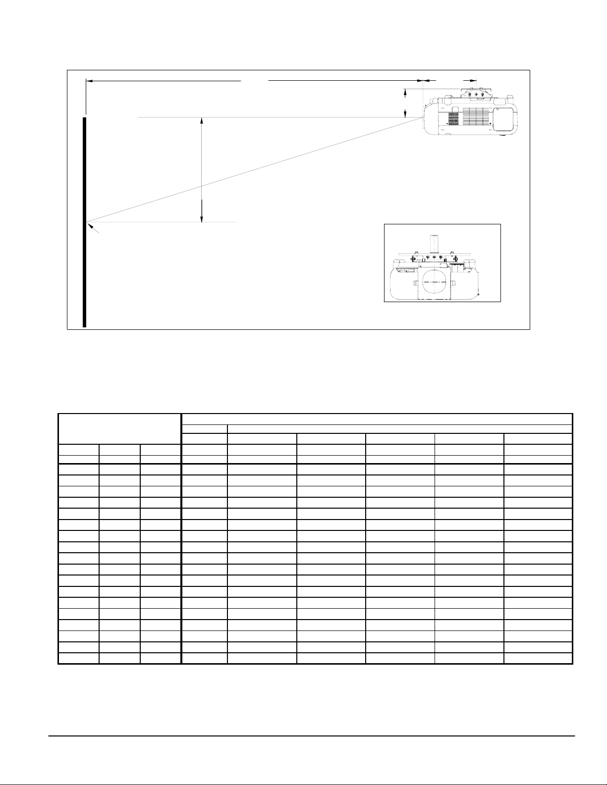
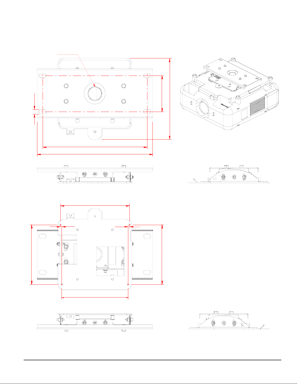
Ceiling Mounted Installation Page 2
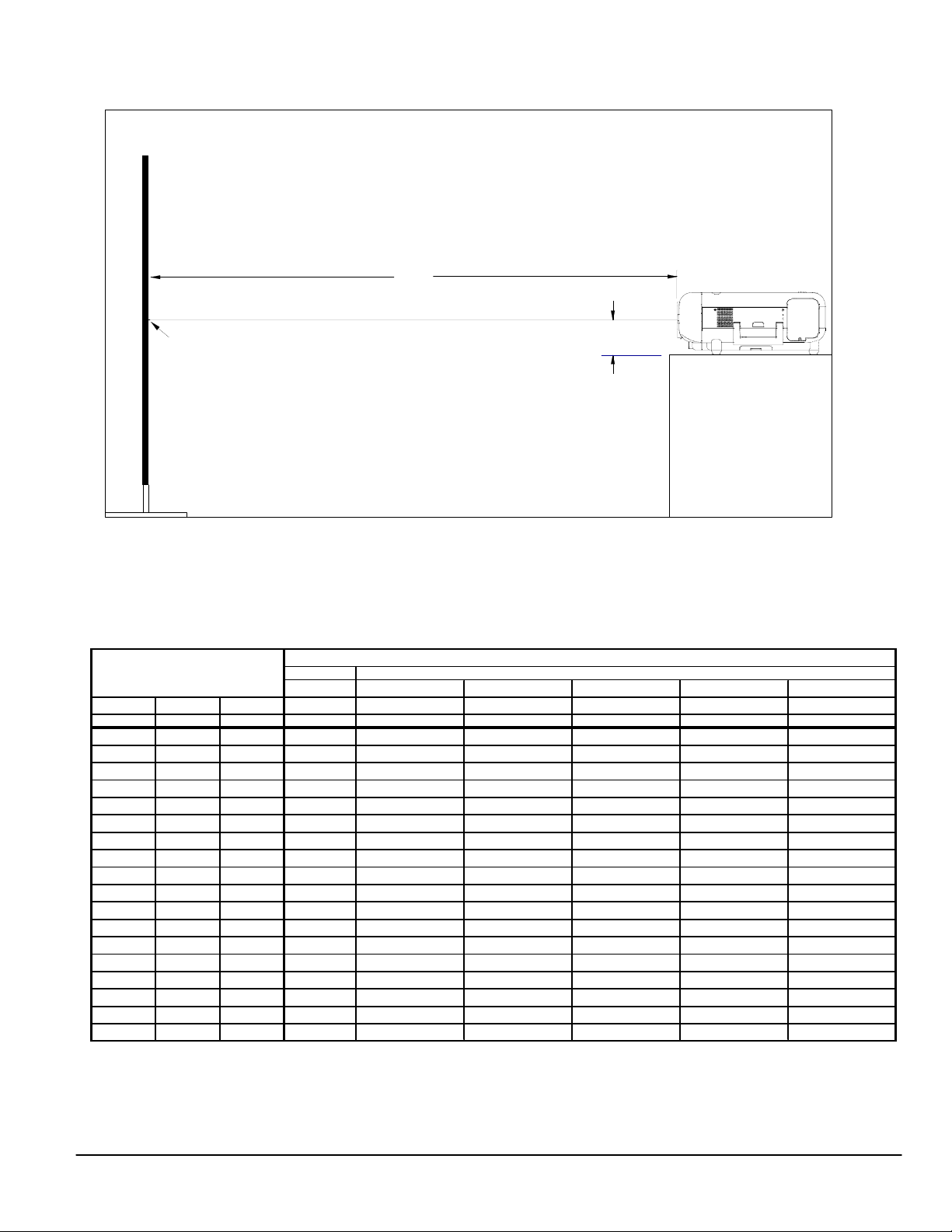
DesktopSetup Page 3
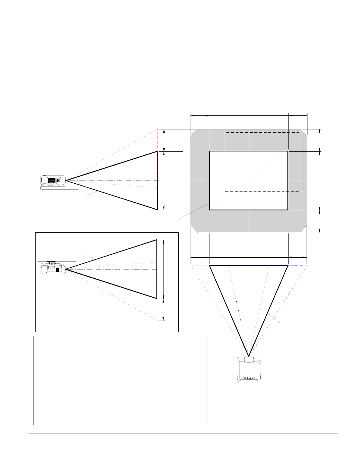
Lens Shift Adjustable Range
GT20ZL Page 4
GT13ZLB/GT19ZL/GT24ZLB/GT34ZLB Page 5
Cabinet Dimensions
Top, Front and Right Side Page 6
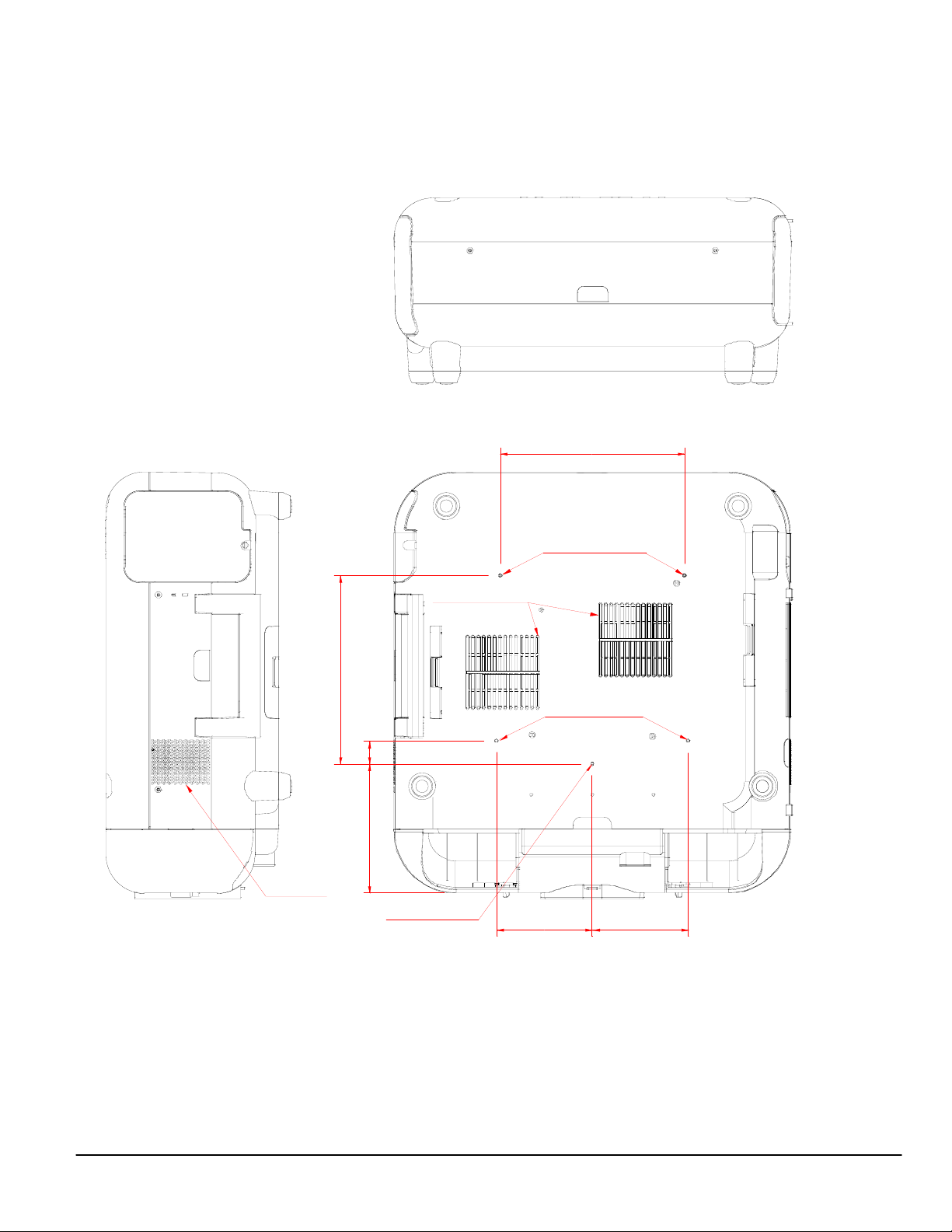
Bottom, Back and Left Side Page 7
Ceiling Mount Dimensions Page 8
Control Codes Page 9
ProductDescription
Type: 3 panel LCD/Dual Lamp Projector Dimensions: 20.4”(W) x 9.5”(H) x 21.8”(D)
1.4” p-Si TFT w/MLA Weight: 40.6 lbs w/o lens
Native Resolution: GT5000: 1024 x 768 (XGA) Brightness: GT5000: up to 6000 ANSI (6 modes available)
GT6000: 1400x1050 (SXGA+) GT6000: up to 5300 ANSI (6 modes available)
Network Ready, integrated wired network adapter Power Lens Shift/Power Zoom/Power Focus
LensSpecifications
GT10RLB Throw Ratio: 1.0:1(approx.) Focal Length: 28.9mm
(ships in June) Screen Sizes: 40”-250” F/#: 2.4
GT13ZLB Throw Ratio: 1.2 - 1.5:1(approx.) Focal Length: 34.5 - 42.5mm
Screen Sizes: 40” - 300” F/#: 2.3 - 2.8
GT19ZL Throw Ratio: 1.7 - 2.2:1(approx.) Focal Length: 48.9 - 63.7mm
Screen Sizes: 40” - 300” F/#: 2.0 - 2.7
GT20ZL Throw Ratio: 2.0 - 2.6:1(approx.) Focal Length: 57.4 - 74.7mm
Screen Sizes: 40” - 300” F/#: 1.8 - 2.5
GT24ZLB Throw Ratio: 2.2 - 3.2:1(approx.) Focal Length: 64.0 – 93.8mm
Screen Sizes: 60” - 400” F/#: 2.5 - 3.2
GT34ZLB Throw Ratio: 3.2 - 4.8:1(approx.) Focal Length: 93.5 - 140.3mm
Screen Sizes: 80” - 500” F/#: 2.5 - 3.3
Notes
• For screen sizes not indicated on the projection charts, use the formulas below.
• If a value in a chart does not match the results of the formulas, use the values in the chart.
• The ceiling must be strong enough to support the projector and the installation must be in accordance with any local
building codes.
• All formulas are based on a 4:3 aspect ratio and screen.
• 4:3 sources can be displayed on a 16:9 screen without vertical “squeezing”, see “Aspect Ratio” in the user manual.
• Distances are in inches, for millimeters multiply by 25.4.
• Distances may vary ±5%.
Formulas (for a 4:3 screen)
Units: Inches (for millimeters multiply final number by 25.4)
Definitions:
Projection Formulas: H= Horizontal Screen Width (4:3)
GT10RLB: C = 1.0034H – 2.087 (ships in June 2003) V= Vertical Screen Height (4:3)
GT13ZLB: C(Wide) = 1.2023H – 2.485 ------ C(Tele) = 1.4890H – 2.433 C= Throw Distance
GT19ZL: C(Wide) = 1.7010H – 3.385 ------ C(Tele) = 2.2392H – 3.272
GT20ZL: C(Wide) = 2.0021H – 3.987 ------ C(Tele) = 2.6237H – 3.949 Screen Formulas:
GT24ZLB: C(Wide) = 2.2181H – 4.895 ------ C(Tele) = 3.2670H – 4.836 H= Screen Diagonal x 4/5
GT34ZLB: C(Wide) = 3.2445H – 7.016 ------ C(Tele) = 4.9132H – 6.863 V= Screen Diagonal x 3/5
Screen Diagonal = H x 5/4
Note:Tilting the front of the projector up or down by more than 45° from level could reduce lamp life by up to 20%.
www.necvisualsystems.com GT5000/6000 Page 1 of 9