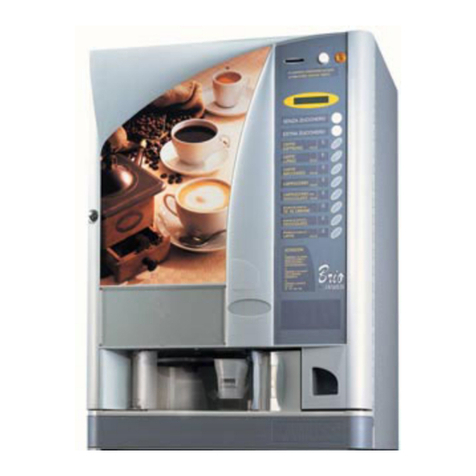
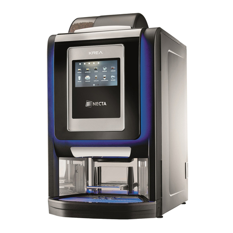
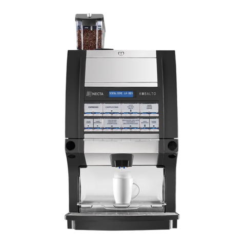
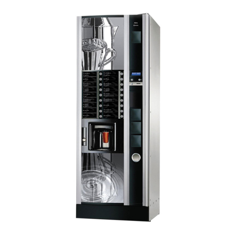
3
© by NECTA VENDING SOLUTIONS SpA 0101 Brio C-I
USING THE VENDING MACHINES OF HOT
DRINKS IN OPEN CONTAINERS
(Ex.: plastic cups, ceramic cups, jugs)
Thevendingmachinesofdrinksinopencontainersshould
be used only to sell and dispense drinks obtained by:
- brewing products like coffee and tea;
- reconstituting instant and lyophilized products;
These products should be declared by the manufacturer
as "suitable for automatic vending" in open containers.
The dispensed products should be consumed imme-
diately. Under no circumstances should they be pre-
served and/or packed for later consumption.
Any other use is unsuitable and thus potentially danger-
ous.
POSITIONING THE VENDING MACHINE
The vending machine is not suitable for outdoor installa-
tion.It mustbe installedin adry roomwhere thetempera-
ture is between 2° C and 32° C, and not where water jets
are used for cleaning (e.g. in large kitchens, etc.).
The machine should be placed close to a wall, so that the
back panel is at a minimum distance of 4 cm from it and
correct ventilation may be ensured.
Themachinemust neverbecovered with clothor the like.
The machine should be positioned with a maximum incli-
nation of 2°.
Ifnecessary provide proper levelling byway ofthe adjust-
able feet included.
Important notice!!
Access to the machine interior for maintenance and/or
repairs is via the back panel.
Therefore, provisions should be made for the machine to
be rotated, thus allowing removal of the back panel.
Positioning the machine on a cabinet
The machine can be installed on a table or on any other
suitable stand (recommended height is 820 mm).
Ifpossible,itisadvisabletousethespecialcabinet,which
can house the liquid waste tray, the water supply kit, the
payment system and, in the case of very hard water, the
softener unit.
WARNING FOR INSTALLATION
The machine installation and the following mainte-
nance operations should be carried out by qualified
personnel only, who are trained in the correct use of
the machine according to the standards in force.
The machine is sold without payment system, therefore
theinstaller of such system hassole responsibilityfor any
damagetothemachineortothingsandpersonscausedby
faulty installation.
Theintegrity ofthevending machineandits conform-
ity with the rules and regulations in force for its
relevant systems must be checked by qualified per-
sonnel at least once a year.
PRECAUTIONS IN USING THE MACHINE
The following precautions will assist in protecting the
environment:
- use biodegradable products only to clean the machine;
- adequately dispose of all containers of the products
used for loading and cleaning the machine;
- switch the machine off during periods of inactivity, thus
achieving considerable energy savings.
WARNING FOR SCRAPPING
Wheneverthemachineistobescrapped,thelawsinforce
regarding environment protection should be strictly ob-
served. More specifically:
- ferrous and plastic materials and the like are to be
disposed of in authorized areas only;
- insulating materials should be recovered by qualified
companies.
TECHNICAL SPECIFICATIONS
Height 750 mm
Width 540 mm
Depth 550 mm
Height of cabinet 820 mm
DIMENSIONS
Power supply voltage 230 V~
Frequency 50 Hz
Installed power
- Espresso 1.4 kW
- Instant 1.9 kW
