3
© by N&W GLOBAL VENDING SpA 0603 265 - 00
POSITIONING THE VENDING MACHINE
The vending machine is not suitable for outdoor installa-
tion.Itmustbepositionedinadryroomwherethetempera-
tureremainsbetween2°Cand32°C,andnotwherewater
jets are used for cleaning (e.g. in large kitchens, etc.).
The machine can be placed close to a wall, but with the
back panel at a distance of at least 4 cm from it to ensure
correct ventilation. The machine must never be covered
with cloth or the like.
The machine should be positioned on a level surface.
Important notice!!
Access to the machine interior for maintenance and/or
repairs is via the back panel and from the side panels.
Therefore the machine is designed to be rotated, thus
allowingremovalofthebackpanelandofthesidepanels.
Installation on a cabinet
The machine can be installed on a table or on any other
suitable stand (recommended height is 830).
Ifpossible,itisadvisabletousethespecialcabinet,which
can house the liquid waste tray, the water supply kit, the
payment system and, in the case of very hard water, the
softener unit.
WARNING FOR INSTALLATION
The machine installation and the following mainte-
nance operations should be carried out by qualified
personnel only, who are trained in the correct use of
the machine according to the standards in force.
The machine is sold without payment system, therefore
theinstaller ofsuch systemhas soleresponsibility forany
damage to the machine or to things and persons caused
byfaulty installation.
The integrity of the machine and compliance with the
standardsoftherelevantsystemsmustbecheckedat
least once a year by qualified personnel.
All packing materials shall be disposed of in a manner
which is safe for the environment.
PRECAUTIONS IN USING THE MACHINE
The following precautions will assist in protecting the
environment:
- use biodegradable products only to clean the machine;
- adequately dispose of all containers of the products
used for loading and cleaning the machine;
- switch the machine off during periods of inactivity, thus
achieving considerable energy savings.
WARNING FOR SCRAPPING
Thesymbol indicatesthatthemachinemaynotbe
disposed of as ordinary waste; it must be disposed of in
accordance with the provisions of the European directive
2002/96/CE(WasteElectricalandElectronicsEquipments
-WEEE)andofanyresultingnationallaws,forpreventing
any possible negative consequences to the environment
and to health.
For correct disposal of the machine, contact our sales
organisation or our after-sales service, or an authorised
waste disposal facility.
TECHNICAL SPECIFICATIONS
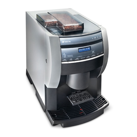
DIMENSIONS
Height 500 mm
Width (with external tank) 508 mm
Depth 528 mm
Overall depth with door open 724 mm
Weight 28 Kg
Fig. 2
Power supply voltage 120 V~
Power supply frequency 60 Hz
Installed power 1300 W
