Nedap TRANSIT User manual

2005-12-22 Part no : 5268516
TRANSIT Quick Installation Guide AMERICAS
Precauciones de seguridad
Las siguientes precauciones de seguridad deben ser realizadas durante el uso, mantenimiento y
reparación.
FCC ID : CGD TRANSIT
El dispositivo se conforma con
la parte 15 de las reglas de
FCC. La operación es
susceptible a las condiciones
siguientes:
(1) Este dispositivo no puede
causar interferencia
perjudicial, y (2) este
dispositivo debe aceptar
ninguna interferencia que
puede causar undesired
operación.
•The TRANIT debe ser instalado y mantenido por personal calificado.
•Desconecte la fuente de poder antes de remover alguna de las partes.
•The TRANSIT debe ser conectado polo a tierra.
•Para estar seguros de la seguridad, no cambie o agregue ninguna
parte amenos que sea mencionado en este manual o indicado por
NEDAP N.V.
•PRECAUCION: para protección contra riesgo de fuego remplace los
fusibles solo por unos del mismo tipo y clasificación.
•The TRANSIT para los Estados Unidos y Canadá debe usar corriente
de 24VDC, clase 2, un sistema de poder bajo, de acuerdo con las
regulaciones locales.
•The TRANIT para USA y Canadá debe venir con 45 metros de cable
de el distribuidor y debe tener la apropiada protección de acuerdo a
las regulaciones locales. Código Nacional Eléctrico (NEC) para USA y
Código Eléctrico Canadiense (CEC) para Canadá.
Montaje
245 mm (9.6 inch)
107 mm (4.2 inch) 292 mm (11.5 inch) 310 mm (12.2 inch)
100mm (3.94 inch)
Holes Ø9 mm (0.35 inch)
M16 (2x) Data and I/O 5-10 mm 0.2-0.4 inch
M20 Mains 10-14mm 0.4-0.6 inch
100 mm (3.94 inch)
Membrane vent
The TRANSIT puede ser instalado in cualquier posición en la pared o poste. Para montaje en un poste un equipo
adicional es requerido (numero de la parte 5626595). Tiene 2 orientaciones principales.
Horizontal: emite anchura 80 grados, la orientación predefinida.
Vertical: emite anchura 40 grados. Recomendado para instalaciones de multilane para evitar la cruz sobre lee.
Esta información se proporciona para la guía, y con ninguna garantía en cuanto a su certeza ni con lo completo; su publicación transmite no licencia bajo
ninguna patente ni otro derecho, ni hace al editor asume la obligación para ninguna consecuencia de su uso; las especificaciones y la disponibilidad de bienes
mencionados son en ello susceptible cambiar sin nota; no deberá ser reproducido en ninguna manera, en el total ni en parte, sin el consentimiento escrito Del
editor.
TRANSIT Quick Installation Guide AMERICAS
Page 2 of 4 Page 2 of 4
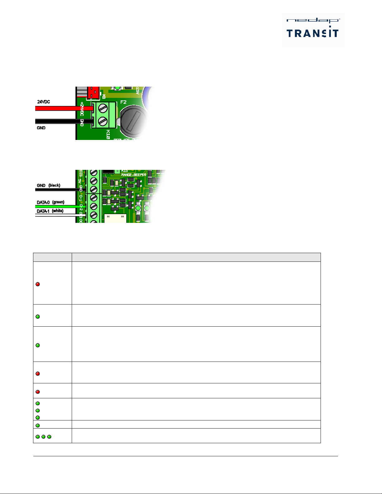
Wiring
Power supply wiring
Fuente de Poder: 24 VDC +/- 10%, *500mA.
Especificaciones del Cabo: 2 x 1.5mm (2 x 15 AWG)
Longitud Maxima: 45 metros (140 ft.). de acuerdo con regulaciones en USA y Canada.
Wiegand Wiring
En la figura abajo el wiring de el wiegand protocolo es mostrado.
Longitud Maxima: 45 metros (140 ft.) de acuerdo con regulaciones en USA y Canada
Led Indicaciones
Un numero de LED’s es usado para indicar el estado actual. La tabla de abajo describe la function de cada LED.
LED Description
STS
Status LED.
Blinking slow: System's heartbeat (0.8 sec on / 0.8 sec off). Indicates that the power is on
and the processor is running.
Blinking fast: Bootloader say's hello. Only indicated for a short period directly after a reset.
Blinking twice: Configuration menu active.
Off: Abnormal situation. Should never be off for longer than 1 second.
ID Identification LED.
This green LED starts to blink fast when a valid transponder is identified.
The LED stays off when no (valid) transponder is identified.
UL
Unlock LED.
The unlock LED is normally off and goes on when a valid transponder is identified. The LED is
turned off when no transponder is identified anymore and the relay-hold-time has elapsed. This
LED can be connected to a Reflex or DC130 antenna.
There is also a relay contact present which has the same function.
NA Lock LED.
Red LED indicating system standby. This LED is normally on and goes off when the unlock LED
goes on. This LED can be connected to a Reflex of DC130 antenna.
INP /
DOOR Input status LED
This red LED is on when the input contact is closed. The input is used as general-purpose input.
+5 VDC
-15 VDC
+15 VDC
Power LEDs
Led active indicates voltage is present
Locked PLL Locked Led active indicates PLL is Locked
RX RX Level Led Bar indicating the received tag signal strength. This LED Bar may also indicate the
presence of radio interference.

TRANSIT Quick Installation Guide AMERICAS
Page 2 of 4 Page 3 of 4
Jumpers
Habilitados or desabilitados el beeper colocando junper K 15 Tango-Beeper.
Beeper OFF Beeper ON
Colocando la Frecuencia
Frequencia necesita ser balanceada cuando el nivel RX barra led esta indicando radio interferencia. Esto puede ser
causado por una de las siguintes condiciones.
•Varios leedores estan en el area de otros leedores (distancia menor que 30 pies).
•Otros dispositivos, como wireless network prensentan interferencia.
Por favor mire la tabla de abajo para frecuencia DIP cambia settings.
FREQ
SEL
SW-1
ON 12345
SUBBAND
5
S5
SUBBAND
6
S5
SW1 on off
Frequency
kHz S1 S2 S3 S4 Frequency
kHz S1 S2 S3 S4
2.438.400 on on on on 2.448.000 on on on on
2.439.000 off on on on 2.448.600 off on on on
2.439.600 on off on on 2.449.200 on off on on
2.440.200 off off on on 2.449.800 off off on on
2.440.800 on on off on 2.450.400 on on off on
2.441.400 off on off on 2.451.000 off on off on
2.442.000 on off off on 2.451.600 on off off on
2.442.600 off off off on 2.452.200 off off off on
2.443.200 on on on off 2.452.800 on on on off
2.443.800 off on on off 2.453.400 off on on off
2.444.400 on off on off 2.454.000 on off on off
2.445.000 off off on off 2.454.600 off off on off
2.445.600 on on off off 2.455.200 on on off off
2.446.200 off on off off 2.455.800 off on off off
2.446.800 on off off off 2.456.400 on off off off
2.447.400 off off off off 2.457.000 off off off off
Pressionar teclado mejorado (SUB)
Este SUB es un teclado montado adicionalmente permite ajustes en el rango de lectura (Parte numero 7800150).
Name Position Description
P2 SQ-
Level
Potenciometro completamente sentido de las manecillas del relojio:
Distancia maxima de lectura.
Potenciometro completamente contra las manecillas:
Distancia minima de lectura. P1
HYST
do not adjust
P2
SQ-LEVEL
TRANSIT Quick Installation Guide AMERICAS
Page 2 of 4 Page 4 of 4
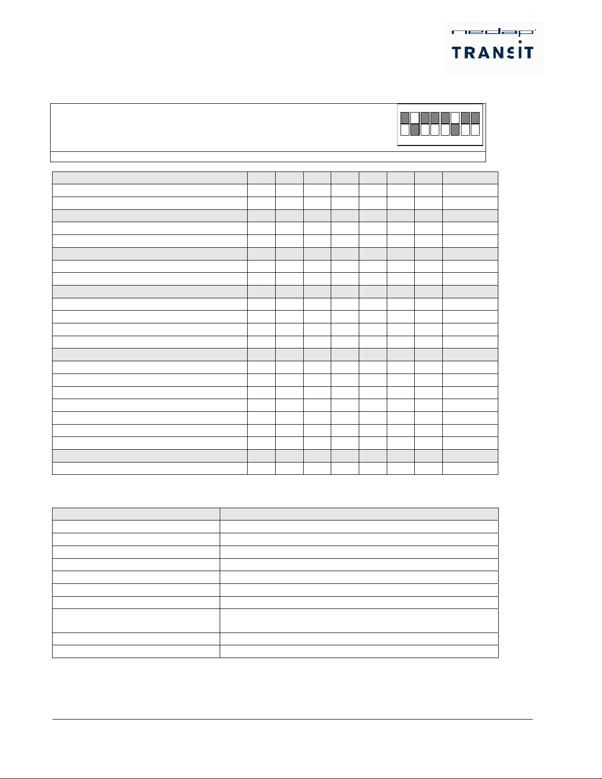
DIP Switch Settings
El TRANSIT (PS-270) tiene 8 DIP-switches, los cuales son usados por el P81 filmware como se describe abajo.
Tipica Combi-Booster HID aplicacion:
Tags aplicables: Todo (incl. combi-Booster HID
Protocolo de comunicacion: Wiegand 26
1 2 3 4 5 6 7 8
ON
Los DIP-Switches son descritos en detalle en la tabla de abajo.
ANTENA FUENTE 8 7 6 5 4 3 2 1
Uso omission de antenna ON x x x x x x x
Microonda y bajo frecuencia de antenna OFF x x x x x x x
FRAMELENGTH 8 7 6 5 4 3 2 1
Largo del Marca 128 bit x ON x x x x x x
Largo del marca 64 bit x OFF x x x x x x
NON_NEDAP DECODING 8 7 6 5 4 3 2 1
Solo Nedap tags habilitados x x ON x x x x x
Nedap y no nedap tags habilitados x x OFF x x x x x
BAUDRATE 8 7 6 5 4 3 2 1
Baud rate 9600 x x x ON ON x x x
Baud rate 1200 x x x ON OFF x x x
Baud rate 19200 x x x OFF ON x x x
Baud rate 38400 x x x OFF OFF x x x
PROTOCOL DE COMMUNICACION 8 7 6 5 4 3 2 1
CR/LF 7E1, Codigo de Barra 39 x x x x x ON ON ON
CR/LF 8N1, Magstripe ISO 7811/2 x x x x x ON ON OFF
CR/LF 7E1, Wiegand 26 (H10301) x x x x x ON OFF ON
CR/LF 8N1, Wiegand 32 x x x x x ON OFF OFF
CR/LF 7E1, Wiegand 37 (H10302 / H10304) x x x x x OFF ON ON
CR/LF 8N1, FF-56 x x x x x OFF ON OFF
CR/LF 7E1, HID Corporate 1000 x x x x x OFF OFF ON
TEST 8 7 6 5 4 3 2 1
TEST mode x x x x x OFF OFF OFF
Después que cambiar la DEPRESION cambia las necesidades de TRANSITO para ser vueltas a encender.
Especificaciones
ITEM SPECIFICACION
Clase de proteccion IP65 / UL 50
Temperature de operacion -30°C … +50°C (-22°F … +122°F)
Temperature de almacenajen -40°C … +85°C (-40°F … +185°F)
Relative humidity 10 … 93% non-condensing
Rango de identificacion Typical 10 meters (33 ft)
Fuente de poder 24VDC +/- 10%, 500mA
Rango de frequencia 2438.4MHz … 2457.0MHz
EMC In accordance with the 89/336/EEC European directive
EN 50081-1, EN 50082-1, EN 50082-2, ETS 0908
Seguridad EN 60950, UL 60950
Acatar las siguientes regulaciones FCC Part 15.245, ETS 300 440
La denegación
para evitar el choque de etiqueta durante probar, asegura por favor que hay sólo una etiqueta en un presente de tiempo dentro de
la gama de identificación del lector de TRANSITO.
Table of contents
Languages:
Other Nedap RFID System manuals

Nedap
Nedap VP1007-B User manual

Nedap
Nedap uPASS REACH User manual

Nedap
Nedap PROX-BOOSTER 2G User manual

Nedap
Nedap ANPR LUMO User manual

Nedap
Nedap Transit Ultimate User manual

Nedap
Nedap LibAssist User manual

Nedap
Nedap TRANSIT Entry User manual

Nedap
Nedap MidRanger + Antenna Set User manual

Nedap
Nedap NVITE User manual

Nedap
Nedap TRANSIT Entry User manual


