Nedap uPASS Access User manual

www.nedapidentification.com
installation guide
2020-04-22 | v4.09 | Doc. no. 5281326
uPASS Access

uPASS Access | installation guide
2/
33
Contents
1Introduction..................................................................................................................................................................... 4
1.1 Firmware versions ................................................................................................................................................ 4
1.2 Supported tags...................................................................................................................................................... 5
1.3 Tag security........................................................................................................................................................... 6
2Installation ...................................................................................................................................................................... 7
2.1 Safety instruction.................................................................................................................................................. 7
2.2 Mounting instruction............................................................................................................................................. 7
2.3 Antenna coverage ................................................................................................................................................. 9
3Connections................................................................................................................................................................... 10
3.1 Power supply ...................................................................................................................................................... 10
3.2 Communication................................................................................................................................................... 11
3.2.1 RS485 ............................................................................................................................................................. 11
3.2.2 USB ................................................................................................................................................................. 13
3.2.3 Wiegand.......................................................................................................................................................... 14
3.2.4 Magstripe ISO7811/2 .................................................................................................................................... 15
3.3 Inputs.................................................................................................................................................................. 16
3.4 Outputs ............................................................................................................................................................... 17
3.5 Tamper switch .................................................................................................................................................... 18
3.6 Nedap antenna interface .................................................................................................................................... 19
4UHF frequencies............................................................................................................................................................ 20
4.1 Radio regulations ................................................................................................................................................ 20
4.2 Frequency channel selection.............................................................................................................................. 20
5Reader configuration..................................................................................................................................................... 21
5.1 UHFTOOL software ............................................................................................................................................. 21
5.2 Settings ............................................................................................................................................................... 21
5.2.1 Read data ....................................................................................................................................................... 22
5.2.2 Decode Nedap-XS .......................................................................................................................................... 23
5.2.3 Relay / timing.................................................................................................................................................. 24
5.2.4 LED control ..................................................................................................................................................... 25
5.3 Expert settings.................................................................................................................................................... 26
5.3.1 Output............................................................................................................................................................. 26
5.3.2 Output message format ................................................................................................................................. 27
5.3.3 Extra output.................................................................................................................................................... 28
5.3.4 Frequency....................................................................................................................................................... 29

uPASS Access | installation guide
3/
33
5.3.5 Read range ..................................................................................................................................................... 29
5.4 Firmware update................................................................................................................................................. 30
ATechnical specifications................................................................................................................................................ 31
BFCC / IC Statement........................................................................................................................................................ 32
CPart numbers................................................................................................................................................................. 33
DDisclaimer...................................................................................................................................................................... 33
EDocument revision ........................................................................................................................................................ 33

uPASS Access | installation guide
4/
33
1Introduction
The uPASS Access is an ultra-small UHF RFID reader for handsfree door access.
Based passive UHF technology, people are identified up to 2 meters (6.5 feet).
Typical applications include hands-free door access in hospitals, office buildings, gated communities, care homes
and universities.
The uPASS Access is ideal for door post mounting at a height of about 1.5 meters (5 feet). It can be installed directly
onto a wall next to a door, without requiring additional mounting accessories. The reader is IP65 rated, so it can be
used indoors as well as outdoors. Installation cable 5 meter (15 feet) is included.
The uPASS Access supports a variety of industry-standard communication interfaces and protocols, such as RS485,
Wiegand, Magstripe (clock & data) and the Open Supervised Device Protocol (OSDP). This enables seamless integration
into any existing or new access control or parking system.
1.1 Firmware versions
The uPASS Access reader supports different firmware versions. Below an overview of the available firmware versions
and their key features.
Standard firmware
•STANDARD ASCII (CR/LF) protocol.
•Wiegand.
•Magstripe ISO7811/2 (clock & data).
OSDP firmware
•OSDP according to the SIA OSDP v2.1.7 standard.
•Secure channel protocol supported.
•LED and buzzer control through OSDP commands.
•General purpose input (3x) and outputs (2x).
OSDP (Open Supervised Device Protocol) is an access control communications standard developed by the Security
Industry Association (SIA). The OSDP protocol specification can be obtained from the website;
www.securityindustry.org/industry-standards/open-supervised-device-protocol.

uPASS Access | installation guide
5/
33
1.2 Supported tags
Any EPC Class 1 Gen 2 tag is supported by the uPASS Access.
NEDAP formatted UHF tags can have the following formats:
•NEDAP UHF Wiegand tags
These tags will contain all Wiegand information including facility code and parity bits. All Wiegand formats can be
supported. The reader transparently sends this information via the Wiegand outputs. There is no need to change
any DIP-switches or configuration settings. See chapter 3.2.3 for wiring details.
•NEDAP UHF Magstripe tags
These tags will contain all magstripe information. The reader transparently sends this information onto the
magstripe interface. There is no need to change any DIP-switches or configuration settings. See chapter 3.2.4 for
wiring details.
•NEDAP UHF XS tags
These tags are especially programmed in the same format as our TRANSIT tags (Compact-Tag, Window-Button
and Heavy-Duty-Tag). The tags will have a customer-code and id-number.
The reader will modulate the tag-info onto the Nedap antenna interface output, which can be connected to NEDAP
AEOS access control hardware such as the AP1001.

uPASS Access | installation guide
6/
33
1.3 Tag security
EPC (Electronic Product Code) tags were introduced as a possible successor to the barcode with added functionalities.
The tag emits its EPC in plain text. This makes the tags vulnerable to cloning and counterfeiting attacks.
There are a few security measures possible against tag cloning.
TID check *
EPC tags contain a data field known as the Tag Identifier (TID). At the discretion of the EPC tag/card manufacturer, the
value is be factory programmed and locked, ensuring that tags have a unique identity and cannot be cross-copied.
NEDAP UHF tags support a locked serialized TID and the uPASS reader can be configured to read the TID data field.
EPC passwords **
EPC tags have 2 passwords. NEDAP has implemented a two-way authentication anti-cloning method using these 2
passwords. This feature is supported in combination with all NEDAP UHF tags.
EPC Gen2 V2 secure authentication ***
The EPC Gen2 V2 tags support a secure authentication method.
This is the best possible anti-cloning measure available.
The authentication data transmitted between tag and reader are enciphered using AES128 bit encryption. The
encryption keys are diversified using the programmed EPC number to ensure that the keys are different for each tag.
Required is that the tags contain an EPC Gen2 V2 compliant RFID chip. Refer to NEDAP uPASS how to order guide for
product numbers.
* Possible for any UHF tag.
** Possible for all NEDAP UHF tags.
*** Possible for all EPC Gen2 V2 tags.
Tag security is not evaluated by UL.

uPASS Access | installation guide
7/
33
2Installation
2.1 Safety instruction
The following safety precautions should be observed during normal use, service and repair.
•The uPASS Access may only be installed and serviced by qualified service personnel.
•Disconnect the power supply before (dis)connecting any wires, uPASS Access is NOT hot-swappable, so when
making or changing connections, power must be switched OFF.
•The cable shield shall be connected with safety ground and the metal case of the external device(s).
•To be sure of safety, do not modify or add anything to the uPASS Access other than mentioned in this installation
guide or indicated by NEDAP N.V.
2.2 Mounting instruction
The uPASS Access can be mounted to a stone, concrete or wooden wall. Metal may decrease the reading performance.
Nedap recommends to perform read tests when installing the reader on or near metal.
See the picture below for details about the installation dimensions.
Figure 1: uPASS Access dimensions

uPASS Access | installation guide
8/
33
Mount the base-plate on the required location.
Ensure that it is placed correctly covering the cable entry hole. Properly fix the base-plate into its position using the 2
screws. When mounting on a stone or concrete wall drill 5mm holes for the plugs. When mounting on wood, drill with
2.5mm.
Install the uPASS Access reader onto the base-plate.
1. Feed the cable through the cable entry hole. Important note: minimum bending radius 30mm.
2. Attach the top of the uPASS Access onto the base-plate.
3. Fix the assembly using the screw on the bottom.
Figure 2: uPASS Access installation
1
2
3
uPASS Access | installation guide
9/
33
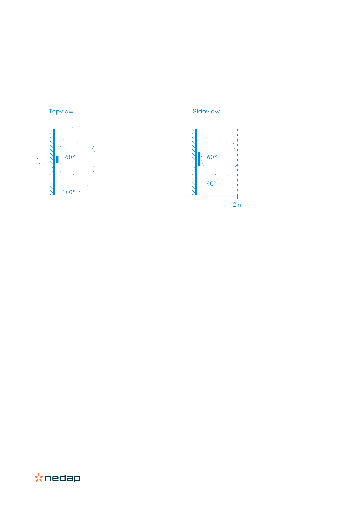
2.3 Antenna coverage
The uPASS Access antenna has a detection coverage area as shown in the picture below.
The read range, which is up to 2 meters, can be adjusted by means of UHFTOOL software setting. See chapter 5.3.5.
Reducing the read range will shrink the complete antenna lobe.
Figure 3: uPASS Access antenna coverage
Maximum read range: 2 meter (6 feet)
Antenna polarization: Horizontal / Vertical
Horizontal reading angle: 160° / 90°
Vertical reading angle: 90° / 60°

uPASS Access | installation guide
10/
33
3Connections
The uPASS Access is supplied with a 5 meter (15 feet) shielded cable with 12 multi-color wires.
RED
Power supply 12 - 24VDC.
BLACK
Power supply 0VDC, DC-Ground.
BROWN
RS485 A (-)
GREEN
RS485 B (+)
GRAY
Data-0 / Clock
PINK
Data-1 / Data
YELLOW
Tamper switch (normally closed)
GRAY/PINK
Tamper switch (common)
RED/BLUE
LED_UL_IN (UL = unlock)
WHITE
LED_NA_IN (NA = not authorized)
PURPLE
Nedap antenna interface. RFMOD antenna modulation (ANT/HF+).
BLUE
Beeper_IN
SHIELD
Shield connected to DC-ground. Connect to metal case of the external device.
3.1 Power supply
The uPASS Access requires DC power supply in the range from 12 – 24V.
Maximum current consumption is 1A @ 12VDC, 1A @ 24VDC.
Connections
RED
Power supply 12 - 24VDC.
BLACK
Power supply 0V / DC-ground.
SHIELD
Shield connected to DC-ground. Connect to metal case of the external device.
Notes
•The minimum voltage at the end of the included cable shall be greater than 12VDC.

uPASS Access | installation guide
11/
33
3.2 Communication
3.2.1 RS485
The uPASS Access reader has an RS485 interface for communication with a host system or for configuring reader
settings. The RS485 interface is a 2-wire half-duplex serial communication interface using balanced lines.
STANDARD and OSDP protocol are available.
Connections
BROWN
RS485 A (-) Balanced RX/TX
GREEN
RS485 B (+) Balanced RX/TX
SHIELD
Shield connected to DC-ground. Connect to metal case of the external device.
STANDARD firmware
This is the default uPASS Access reader firmware version and implements a simple CR/LF protocol.
The RS485 output message format is described in chapter 5.3.2.
Default baud rate is 9600. This can be changed using the UHFTOOL software.
OSDP firmware
The uPASS Access reader has implemented the OSDP protocol including the Secure Channel Protocol.
Default baud rate is 9600. This may be changed using the OSDP_COMSET command.
Perform a firmware update to change from STANDARD to OSDP (or vice versa).
The firmware update procedure is described in chapter 5.4.
RS485 point-to-point communication
Termination resistors (120 Ω) are recommended to prevent unwanted signal reflections on long RS485 communication
lines. The resistors should be installed at both ends of the communication line.
Figure 4: RS485 point-to-point communication (uPASS Access Rev. C)
The uPASS Access reader models before 2020 (Rev. A/B) have a fixed termination resistor. This means you don’t need
to install a separate termination resistor. See Figure 5.
Figure 5: RS485 point-to-point communication (uPASS Access Rev. A/B)
Notes
•Use shielded twisted pair cable when extending the RS485 wiring beyond the standard 5 meter cable.
•Maximum RS485 cable length 1200 meters (6000 feet).
•The RS485 interface is disabled while the USB interface is in use.
HOST
A
B
120
Ω
120 Ω
uPASS
Rev. C
A
B
uPASS
Rev. A/B
HOST
A
B
120
Ω
A
B
120 Ω

uPASS Access | installation guide
12/
33
RS485 multi-drop communication
Multi-drop communication requires an addressable communication protocol, such as OSDP.
Termination resistors (120 Ω) are recommended to prevent unwanted signal reflections on long RS485 communication
lines. The resistors should be installed at both ends of the communication line. See Figure 6 below.
Figure 6: RS485 multi-drop communication
Notes
•The uPASS Access reader models before 2020 (Rev. A/B) have a fixed termination resistor, which cannot not be
disabled. This means that these readers should only be used in point-to-point communication.
•Use shielded twisted pair cable when extending the RS485 wiring beyond the standard 5 meter cable.
•Maximum RS485 cable length 1200 meters (6000 feet).
•The RS485 interface is disabled while the USB interface is in use.
HOST
A
B
120
Ω
120 Ω
uPASS
A
B
A B
uPASS
A B
uPASS

uPASS Access | installation guide
13/
33
3.2.2 USB
The uPASS Access reader features an USB interface for service, installation and firmware upgrade purposes.
The Mini-USB connector is located on the bottom of the device and can only be reached when the bottom screw is
opened and the uPASS Access is lifted away from the base-plate. This ensures that unauthorized modifications to the
reader settings can be detected using the tamper switch.
The USB interface can be used to configure the reader using the UHFTOOL software.
USB driver
Make sure your computer is connected with internet. Connect the uPASS Access reader to your computer via the USB
cable. The USB drivers may be installed automatically. In case you need to install the USB drivers manually, please go
to the website www.ftdichip.com/Drivers/VCP.htm and download the VCP (Virtual Com Port) drivers. After successful
installation of the USB drivers the reader will appear in the Windows device manager in "Ports (COM & LPT)" section.
Notes
•While the USB cable is connected, the RS485 interface is disabled !

uPASS Access | installation guide
14/
33
3.2.3 Wiegand
The Wiegand and Magstripe ISO7811/2 (clock & data) interface share the same connections. This means that only
Wiegand or Magstripe can be used and not both simultaneously
Wiegand connections
GRAY
Data-0
PINK
Data-1
GROUND
Ground
SHIELD
Shield connected to DC-ground. Connect to metal case of the external device.
Message format
The Wiegand/Magstripe output format is determined by the programmed format of the tag. Make sure to order the
correct tag formatting if you want to use the Wiegand interface. See the uPASS how to order guide for more information.
If UHF tags is not programmed in Wiegand format, you may configure Wiegand output format using the 'Extra output'
settings. See for more details chapter 5.3.3.
Wiegand timing
The figure below shows the Wiegand protocol timing.
Tpw
5V
0V
DATA-1
5V
0V
DATA-0
Tpi
Tpi
Tpw
Figure
7: Wiegand timing details
Timing constants
Pulse interval time (Tpi)
1msec
Pulse
width time (Tpw) 50µsec
OSDP firmware
The OSDP firmware does not support the Wiegand interface!
Notes
•Use shielded cable (4 x 0.25 mm2) when extending the Wiegand wiring beyond the standard 5 meter cable.
•Maximum Wiegand cable length 150 meters (500 feet).

uPASS Access | installation guide
15/
33
3.2.4 Magstripe ISO7811/2
The Magstripe ISO7811/2 (clock & data) and Wiegand interface share the same connections. This means that only
Wiegand or Magstripe can be used and not both simultaneously.
Magstripe connections
GRAY
Clock
PINK
Data
GROUND
Ground
SHIELD
Shield connected to DC-ground. Connect to metal case of the external device.
Message format
The Wiegand/Magstripe output format is determined by the programmed format of the tag. Make sure to order the
correct tag formatting if you want to use the Wiegand or Magstripe interface. See the uPASS how to order guide for
more information.
If UHF tags is not programmed in Wiegand format, you may configure Magstripe output format using the 'Extra output'
settings. See for more details chapter 5.3.3.
Magstripe timing
The Magstripe (clock & data) interface follows the ISO7811/2 specifications. The figure below shows the timing for one
character. Each bit consists out of one period low (220µsec) and two periods high (440µsec). The bit times have an
accuracy of 10 percent. The data-signal is valid and stable on the falling edge of the clock-signal.
odd parity
msb
lsb
3300µsec
0
1
1
0
1
220µsec
660µsec
5V
0V
CLK
5V
0V
DAT
Figure
8: Magstripe timing details
Timi
ng constants
Clock period
660µsec
Clock high
440µsec
Clock low
220µsec
Data preamble
11msec
Data postamble
11msec
OSDP firmware
The OSDP firmware does not support the Magstripe interface!
Notes
•Use shielded cable (4 x 0.25 mm2) when extending the Magstripe wiring beyond the standard 5 meter cable.
•Maximum Magstripe cable length 150 meters (500 feet).

uPASS Access | installation guide
16/
33
3.3 Inputs
The uPASS Access reader has 3 digital inputs (active low).
Connect the input to ground to active the input. Use a potential-free (relay) contact. Leave unconnected otherwise.
Connections
RED/BLUE
Input 0 - LED_UL_IN (active low)
WHITE
Input 1 - LED_NA_IN (active low)
BLUE
Input 2 - Beeper_IN (active low)
BLACK
Ground
SHIELD
Shield connected to DC-ground. Connect to metal case of the external device.
Standard firmware
The digital inputs can be used to control the LED and buzzer. See details about LED/buzzer control in chapter 5.2.4.
OSDP firmware
The digital inputs are general purpose inputs.
Upon status change the reader will send input status report message OSDP_ISTATR.
The current input status can be requested by sending the input status report request message OSDP_ISTAT

uPASS Access | installation guide
17/
33
3.4 Outputs
The uPASS Access reader has 2 digital outputs. The function of the digital outputs is dependent upon the installed
firmware version. See description below.
STANDARD firmware
The outputs are used for Wiegand or Magstripe communication. See respectively chapters 3.2.3 or 3.2.4.
OSDP firmware
The outputs are general purpose outputs. The outputs are open-collector and can be used to activate an external relay.
Use the OSDP_OUT command to control the output state. The outputs allow for direct activation and deactivation plus
timed operation (OSDP output control compliance level 3). The permanent command is volatile (does not transcend
power cycles)
When the status of an output changes the reader will send an output status change report message OSDP_OSTATR.
Connections
GRAY
Output 0 / Data-0 / CLK
PINK
Output 1 / Data-1 / DAT
GROUND
Ground
SHIELD
Shield connected to DC-ground. Connect to metal case of the external device.
Output ratings
Type Open collector (internal weak 5V pull-up resistor)
Max. voltage +24 VDC
Max. current 200 mA

uPASS Access | installation guide
18/
33
3.5 Tamper switch
An internal magnet provides tamper indication when the reader is dismounted. This contact may be connected to an
external alarm system. The contacts are normally closed when the reader is in place.
Tamper switches of multiple readers can be connected in series
Connections
YELLOW
Tamper switch (normally closed)
GRAY/PINK
Tamper switch (common)
SHIELD
Shield connected to DC-ground. Connect to metal case of the external device.
Contact ratings
Max. current 50 mA (0.5 Volt voltage drop)
Max. switching voltage +24 VDC
OSDP firmware
The tamper switch status is NOT reported through OSDP communication protocol
Notes
•Use shielded cable (2 x 0.25 mm2) when extending the wiring beyond the standard 5 meter cable.
•Maximum cable length 150 meters (500 feet).

uPASS Access | installation guide
19/
33
3.6 Nedap antenna interface
The Nedap antenna interface is used to connect the uPASS Access to NEDAP AEOS access control hardware such as
the AP1001. Instead of proximity antenna the uPASS Access can be connected.
Connections
PURPLE
Nedap antenna interface. RFMOD antenna modulation (ANT/HF+)
BLACK
Nedap antenna interface. Ground, shield (ANT/HF-).
SHIELD
Shield connected to DC-ground. Connect to metal case of the external device.
OSDP firmware
The OSDP firmware does not support the Nedap antenna interface.
Notes
•Nedap-XS formatted UHF tags are required to use the Nedap antenna interface!
•Use RG58U coax cable when extending the wiring beyond the standard 5 meter cable.
•Maximum cable length 100 meters (350 feet).

uPASS Access | installation guide
20/
33
4UHF frequencies
4.1 Radio regulations
The uPASS Access reader operates on the 860 – 960 MHz band. Regulations in this band are not standardized world-
wide. Generally the regulations can be divided into several regions.
Per region a specific frequency band is available. This frequency band is divided into frequency channels. If local radio
regulations require frequency hopping (FHSS), then the uPASS Access automatically selects and uses the available
channels.
4.2 Frequency channel selection
If no frequency hopping is required, you should select an available frequency channel manually. This can be realized as
described below. Select an available frequency channel to achieve the best performance and to avoid interference from
other readers or equipment.
Use UHFTOOL to setup the frequency channel selection. See for more details chapter 5.3.4.
Other manuals for uPASS Access
2
Table of contents
Other Nedap RFID System manuals

Nedap
Nedap VP1007-B User manual

Nedap
Nedap uPASS TARGET User manual

Nedap
Nedap TRANSIT Entry User manual

Nedap
Nedap TRANSIT Entry User manual

Nedap
Nedap uPASS REACH User manual

Nedap
Nedap MidRanger + Antenna Set User manual

Nedap
Nedap Transit Ultimate User manual

Nedap
Nedap TRANSIT User manual

Nedap
Nedap ANPR LUMO User manual

Nedap
Nedap LibAssist User manual


