Nedap Transit Ultimate User manual

www.nedapidentification.com
installation guide
2020-05-13 | v5.08 | Doc. no. 5481104
TRANSIT Ultimate

TRANSIT Ultimate | installation guide
2/
40
Contents
1Introduction ........................................................................................................................................................................ 4
1.1 Product description.................................................................................................................................................. 4
1.2 Ultimate features ..................................................................................................................................................... 5
2Installation .......................................................................................................................................................................... 6
2.1 Safety precautions ................................................................................................................................................... 6
2.2 Installation guidelines ............................................................................................................................................. 6
2.3 Mounting instructions.............................................................................................................................................. 7
2.3.1 TRANSIT Ultimate dimensions ........................................................................................................................... 7
2.3.2 Wall mounting...................................................................................................................................................... 8
2.3.3 Pole mounting...................................................................................................................................................... 9
2.3.4 Weather protection hood .................................................................................................................................. 10
2.4 Installing the security key pack ............................................................................................................................ 11
2.5 Installing a communication board ........................................................................................................................ 12
3OSDP Interface Board ...................................................................................................................................................... 13
3.1 TRANSIT wiring ...................................................................................................................................................... 13
3.2 RS485-OSDP wiring............................................................................................................................................... 14
3.3 TRANSIT configuration .......................................................................................................................................... 15
4Connections ...................................................................................................................................................................... 16
4.1 Overview ................................................................................................................................................................. 16
4.2 Power supply.......................................................................................................................................................... 17
4.2.1 AC mains ............................................................................................................................................................ 17
4.2.2 DC supply input.................................................................................................................................................. 17
4.2.3 DC output ........................................................................................................................................................... 18
4.3 Communication ...................................................................................................................................................... 19
4.3.1 USB..................................................................................................................................................................... 19
4.3.2 Wiegand / Magstripe / Barcode ........................................................................................................................ 20
4.3.3 RS232................................................................................................................................................................. 21
4.3.4 RS422-485 ........................................................................................................................................................ 21
4.4 Digital I/O ............................................................................................................................................................... 22
4.4.1 Relay output....................................................................................................................................................... 22
4.4.2 Read disable input............................................................................................................................................. 23
4.4.3 Tamper switch ................................................................................................................................................... 24
4.4.4 General purpose inputs..................................................................................................................................... 25
4.5 Special connections............................................................................................................................................... 26

TRANSIT Ultimate | installation guide
3/
40
4.5.1 Proximity antenna ............................................................................................................................................. 26
4.5.2 Nedap antenna modulation .............................................................................................................................. 27
5Firmware update............................................................................................................................................................... 28
6Configuration..................................................................................................................................................................... 29
6.1 Ultimate mode........................................................................................................................................................ 29
6.2 Range beeper ......................................................................................................................................................... 30
6.3 Serial communication select................................................................................................................................. 30
6.4 Frequency select.................................................................................................................................................... 31
6.4.1 Frequency select display & buttons................................................................................................................. 31
6.4.2 Frequency select dip-switches......................................................................................................................... 31
6.5 Read range control................................................................................................................................................. 32
6.6 Microwave time-sharing ........................................................................................................................................ 33
7LED indications.................................................................................................................................................................. 34
7.1 Main board LED indications ................................................................................................................................... 34
7.2 TAB board LED indications .................................................................................................................................... 35
ATechnical specification..................................................................................................................................................... 36
BFrequency channels.......................................................................................................................................................... 37
CNedap part numbers......................................................................................................................................................... 38
DFCC / IC statement ........................................................................................................................................................... 39
EDisclaimer.......................................................................................................................................................................... 40
FDocument revision............................................................................................................................................................ 40

TRANSIT Ultimate | installation guide
4/
40
1Introduction
1.1 Product description
The TRANSIT Ultimate is a long-range reader, based on semi active RFID technology, which enables automatic vehicle
identification at distances of up to 10 meters (33 ft.) and speeds of up to 200 km/h (125 mph).
Key features
•Robust industrial design
•Read range up to 10 meters [33 ft.]
•Object speed up to 200 km/h [125 mph]
•Adjustable read range
•Selectable frequency channels
•Variety of integrated communication interfaces
•3 color LED indication
•Tag authentication based on AES encryption
•Backwards-compatible with previous TRANSIT readers.
Frequency channels
The TRANSIT Ultimate operates on a factory-set frequency channel. Different frequency channels allow multiple
readers to operate in close vicinity of each other without interference.
Read range adjustment
The reader efficiently resolves typical multi-lane, entry and exit reader challenges. The read range of the TRANSIT
Ultimate can be adjusted to offer secure and reliable identification in demanding applications.
Housing & mounting
The TRANSIT Ultimate is intended for outdoor installation.
The weatherproof TRANSIT Ultimate reader features an IP66 certified housing. The reader operates reliable under
harsh environmental conditions and is able to withstand exposure to rain, snow and ice. Wall mounting equipment is
included.
Interfaces & protocols
The TRANSIT Ultimate is designed for seamless and flexible integration into existing management systems in the
industry, such as security, parking, and logistics. Several communication interfaces to the host system are available
such as RS232, RS422, RS485 and TCP/IP. Also open industry-standards protocols such as OSDP, Wiegand, Magstripe
and Barcode are available.

TRANSIT Ultimate | installation guide
5/
40
1.2 Ultimate features
Encrypted tag authentication
The TRANSIT Ultimate enables encrypted tag authentication for the Ultimate tags: Smartcard Booster Ultimate, LEGIC
Booster Ultimate and Window Tag Ultimate. The authentication uses encryption based upon AES 128-bit keys. Key
diversification is used to ensure that a unique encryption key is used for every tag.
Implementation
The Ultimate-mode features are implemented in the TAB board. The TAB-board performs the authentication or other
Ultimate function using the bi-directional tag communication channel at 433MHz.
Figure 1: TRANSIT Ultimate block diagram
Authentication procedure
The encrypted tag authentication is performed when both antennas (433MHz and 2.45GHz) receive the same id-
number. This ensures that the tag to be authenticated is located in the well-defined directional beam in front of the
reader.
1. Receive Ultimate tag id-number.
2. Send encrypted challenge to the tag.
The challenge is generated by the Security Key Pack based upon random numbers encrypted with a diversified
AES128 key.
3. Receive, decrypt and verify the encrypted challenge response from the tag.
4. When the authentication is successful, the id-number is transmitted on the communication output(s).
The TAB board may be bypassed to make the TRANSIT Ultimate backwards compatible with the TRANSIT Standard.
See chapter 6.1.
TRANSIT - PIC
2.45GHz
433MHz
Ultimate
mode
bypass
Serial com-select
USB-detect
USB
I/F-board
Wiegand
Relay output
Smiley RGB
TAB-board
Security Key Pack
TRANSIT Ultimate
TRANSIT Ultimate | installation guide
6/
40
2Installation
2.1 Safety precautions
The following safety precautions should be observed during normal use, service and repair:
•The TRANSIT Ultimate shall be connected to safety ground.
•Disconnecting from (mains) power supply before removing any parts.
•The TRANSIT Ultimate shall only be installed and serviced by qualified service personnel.
•To be sure of safety, do not modify or add anything other than mentioned in this manual or indicated by NEDAP.
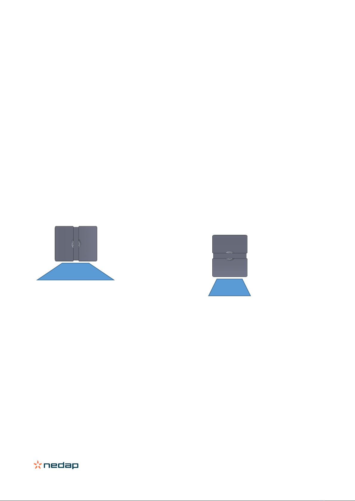
2.2 Installation guidelines
The TRANSIT Ultimate can be installed in any position. The normally expected read range is up to 10 meters. The
hinges should be on top of the reader.
Landscape installation – wide beam
Usually the reader is mounted in the horizontal
position. In this case the coverage area in the
horizontal plane is maximized. The horizontal beam is
80 degrees.
Portrait installation – narrow beam
In some applications a vertical installation is required
to make use of the smaller beam width in the vertical
plane. The vertical beam is 40 degrees. This can be
very useful in applications with multiple lanes to
prevent cross readings.
Wide 80°
Narrow 40°

TRANSIT Ultimate | installation guide
7/
40
2.3 Mounting instructions
See the following chapters for details about the dimensions of the reader and the mounting brackets and the locations
of the mounting positions.
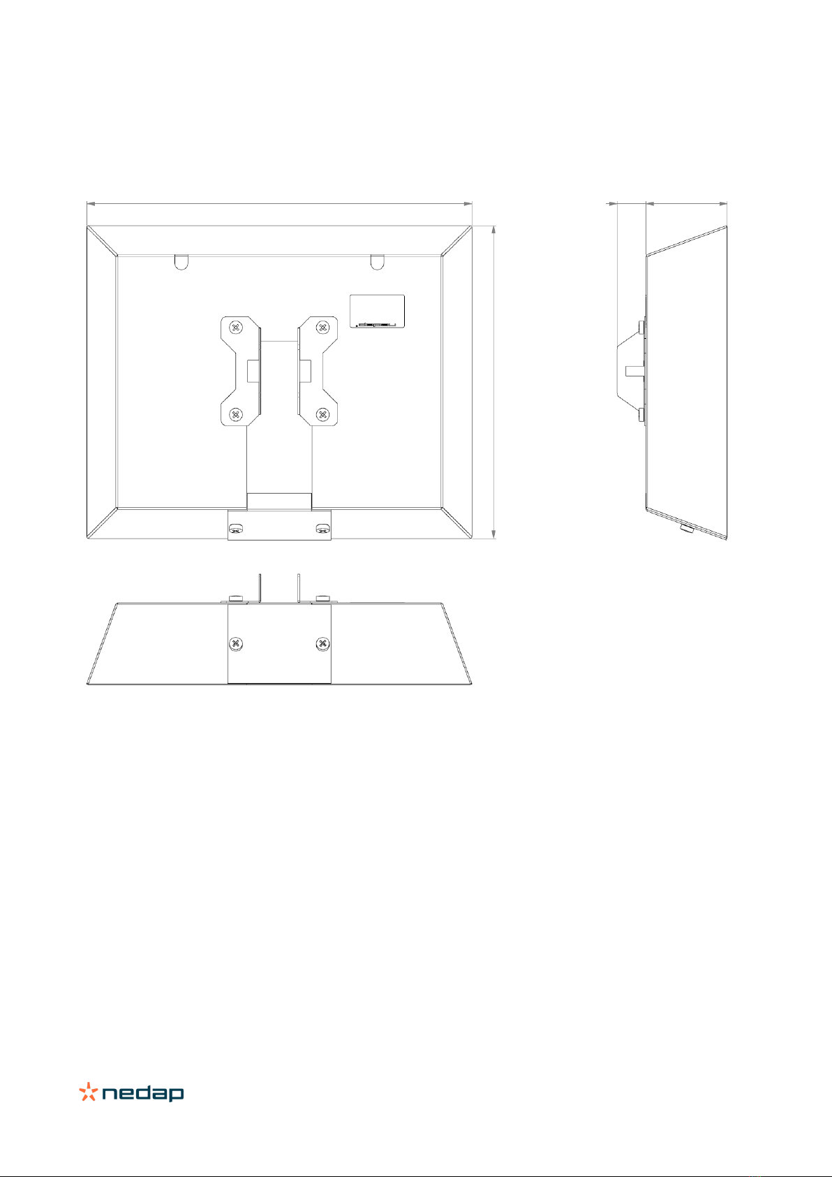
2.3.1 TRANSIT Ultimate dimensions
The picture below shows the dimensions of the TRANSIT Ultimate.
All dimensions are in mm.
Figure 2: Dimensions TRANSIT Ultimate
To guarantee water tightness in all
positions, the cover screws and the
cable glands have to be tightened
according our recommendations.
TRANSIT Ultimate | installation guide
8/
40
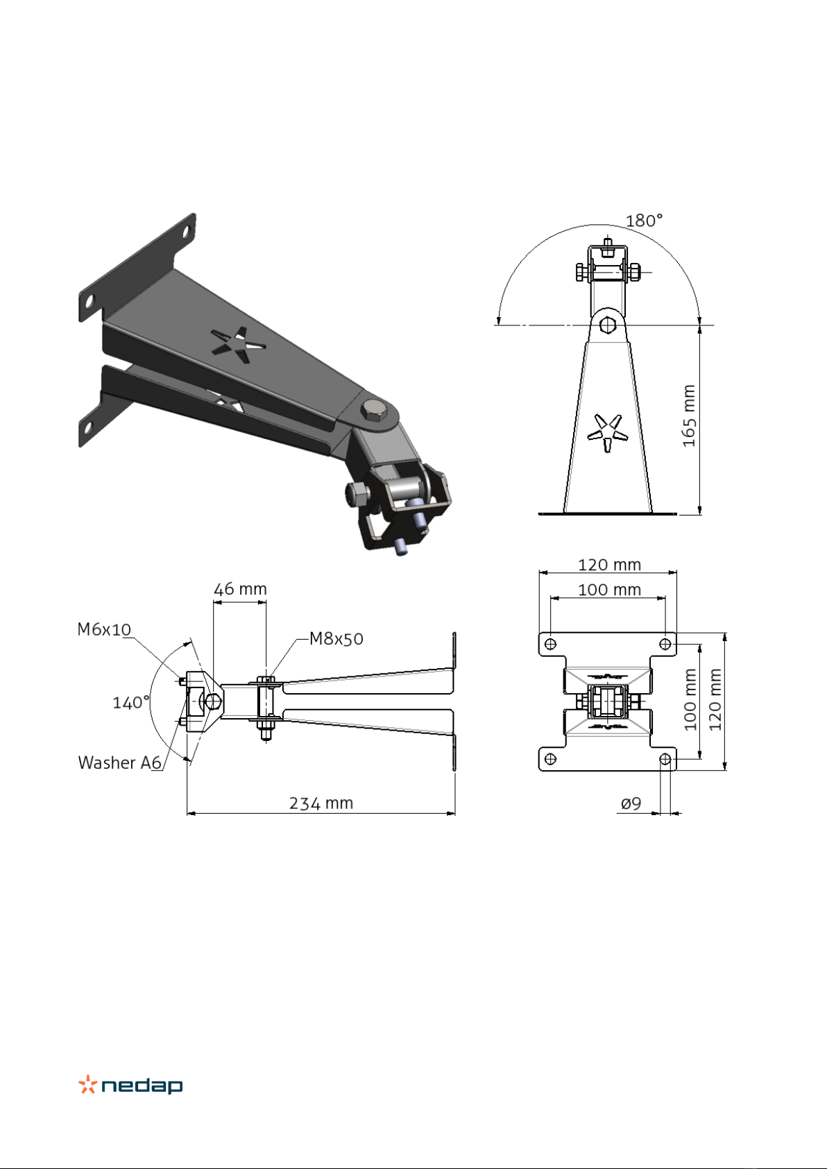
2.3.2 Wall mounting
The Wall Mounting Set is supplied with the TRANSIT Ultimate reader. When the Wall Mounting Set is assembled mount
it to the wall (or to the Pole Mounting Set) based on the dimensions in Figure 3. The TRANSIT Ultimate can be “aimed”
with the Wall Mounting Set and when the bolts are tightened, it will stay in place.
Figure 3: Wall Mounting Set
TRANSIT Ultimate | installation guide
9/
40
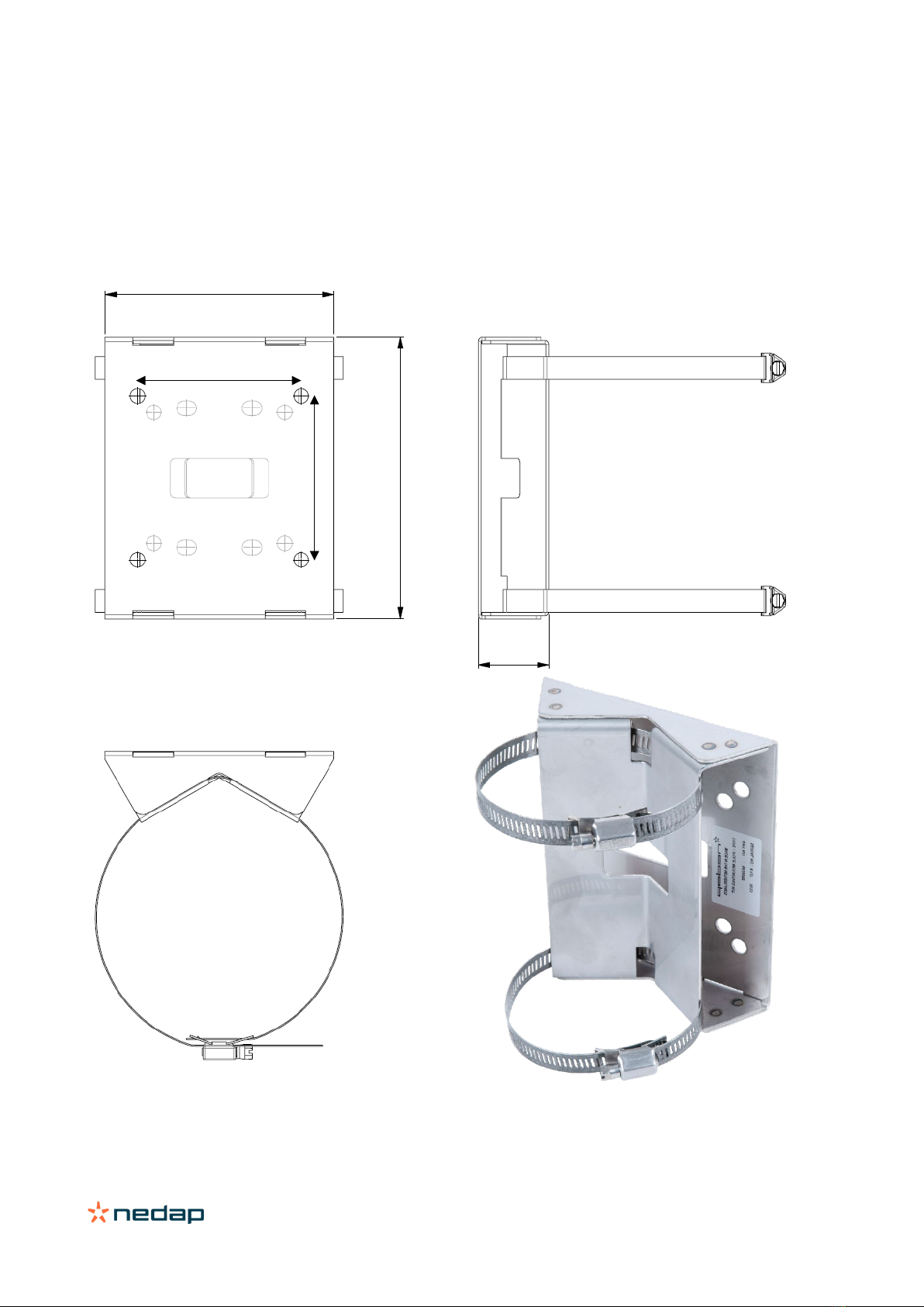
2.3.3 Pole mounting
The TRANSIT Ultimate can be mounted to round poles with maximum diameter of 190 mm and square poles with
maximum diameter of 150 mm using the Pole Mounting Kit.
The Pole Mounting Kit has to be ordered separately (art. no. 5626595).
The Wall Mounting Set will be mounted onto the Pole Mounting Kit.
Figure 4: Dimensions Pole Mounting Kit
140 mm
172 mm
43 mm
100 mm
100 mm
TRANSIT Ultimate | installation guide
10/
40
2.3.4 Weather protection hood
The Weather Protection hood is recommended when the reader is installed in direct sunlight.
The Weather Protection Hood has to be ordered separately (art. no. 9218327).
Figure 5: Dimensions Weather Protection Hood
287 mm
TRANSIT Ultimate | installation guide
11/
40
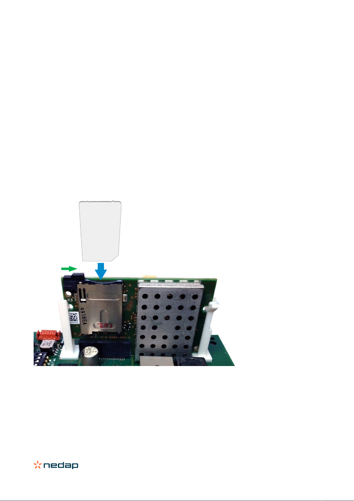
2.4 Installing the security key pack
The optional Security Key Pack (SAM) has to be ordered separately (art. no. 9216537) and is required for the TRANSIT
Ultimate to perform the encrypted authentication on the Ultimate tags. Please follow the procedure below to install the
Security Key Pack into the TRANSIT Ultimate.
Security Key Pack installation procedure
Insert the Security Key Pack (SAM) into the TAB board.
1. Align the notch as indicated in Figure 6 and keep the metal contacts backwards.
2. Push the SAM into the slot until it clicks into place.
3. Set the LOCK-switch to the right to lock the SAM.
4. Enable the Ultimate-mode by setting dip-switch SW2-2 ON. See chapter 6.1.
Removal procedure
1. Set the LOCK-switch to the left to release the SAM.
2. Push the SAM to eject it.
3. Disable the Ultimate-mode by setting dip-switch SW2-2 OFF. See chapter 6.1.
Figure 6: Installing the Security Key Pack (SAM)
SAM
LOCK

TRANSIT Ultimate | installation guide
12/
40
2.5 Installing a communication board
The TRANSIT Ultimate features an on-board USB port and a Wiegand / Magstripe / Barcode interface. See chapter 4.3
for more details.
Other communication interfaces can modularly be installed in the reader by means of a communication interface board.
There are various communication interface boards available for the TRANSIT Ultimate. See appendix C for available
boards and their part numbers.
Make sure to follow all safety precautions outlined in chapter 2.1 when installing or replacing a communication board.
Communication board installation procedure:
1. Open the TRANSIT Ultimate. You can put the cover strut into place to keep the cover open.
2. Disconnect the power supply.
3. Place the communication interface board on the 14-pin header K5 as indicated in the picture below.
4. Make sure that the 4 plastic PCB supports are properly positioned and fixed into the communication board.
5. Read the communication board’s installation guide for additional notes like address setting, jumper settings and
wiring details.
6. Test if the communication works correctly.
7. Close the cover of the TRANSIT Ultimate.
PCC485/OSDP
The PCC485/OSDP converter board is not installed as described above.
Please refer to chapter 3 for more details.

TRANSIT Ultimate | installation guide
13/
40
3OSDP Interface Board
For supporting OSDP on the TRANSIT Ultimate it is required to use the OSDP Interface Board, which includes the
PCC485/OSDP converter. This board implements the OSDP protocol according to the SIA OSDP v2.1.7 standard,
including the Secure Channel Protocol.
You may purchase the TRANSIT Ultimate together with the OSDP Installation Board. This is convenient, because then
the board is already installed by Nedap. See appendix C for part numbers.
This chapter describes how to install the OSDP Interface Board afterwards yourselves. Make sure to follow all safety
precautions outlined in chapter 2.1.
OSDP Interface Board installation procedure
1. Connect the OSDP Interface Board (PCC485) with TRANSIT as described in chapter 3.1.
2. Connect to the RS485-OSDP network as described in chapter 3.2.
3. Setup TRANSIT configuration as described in chapter 3.3.
3.1 TRANSIT wiring
The TRANSIT Ultimate and OSDP Interface Board must be connected as shown in the figure below. The wiring includes
power supply, antenna signal for identification and control for relay output and front cover LED.
Figure 7: TRANSIT / OSDP Interface Board wiring wiring
OSDP Interface Board
TRANSIT
RS485 - OSDP
OSDP_OUT #1
O
SDP_OUT # 0
Power supply
IN-1
IN-2
IN-3
GND
HF+
GND
COM
NC
NO
PCC485
GND
U+
GND
HF+
A
B
GND
T
R
GND
RL
BP
GND
UL
NA
NO
C
NC
A
B
#
A
B
#
NO
C
NC
TRANSIT Ultimate | installation guide
14/
40
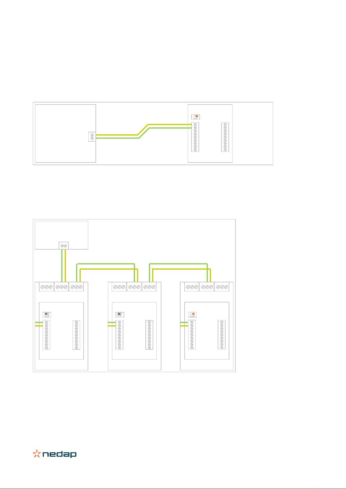
3.2 RS485-OSDP wiring
The RS485-OSDP wiring should be connected to the RS485 connections on the OSDP Installation Board (OSDP-IB) or
directly to the PCC485. See wiring picture below.
For point-to-point communication enable the termination resistor. PCC485 switch 1 to ON position. See picture below.
Figure 8: RS485-OSDP point-to-point wiring
For multi-drop communication disable the termination resistor on the PCC485 on all devices except the last device. The
termination resistor should be enabled on the last device in a multi-drop communication system. See picture below.
Figure 9: RS485-OSDP multi-drop wiring
For more details refer to the separate PCC485 installation guide.
PCC485
A B
OSDP Control Panel
B A
ON
1 2
PCC485
PCC485
PCC485
B A
OSDP Control Panel
#
B A
#
B A
#
B A
#
B A
#
B A
#
B A
OSDP-Kit
OSDP-Kit
OSDP-Kit
B A
ON
1 2
B A
OFF
1 2
B A
1 2
OFF
TRANSIT Ultimate | installation guide
15/
40
3.3 TRANSIT configuration
This chapter describes how to configure the TRANSIT Ultimate reader for OSDP installations.
TRANSIT firmware requirements
The OSDP Interface Board / PCC485 requires to use one of the standard TRANSIT firmware versions, since these
support the manual LED and relay control function.
•P80 v3.00 (no configuration required, use default settings)
•P81 v3.35
•P82 v3.08
•P83 v3.04
•P84 v3.06
•P85 v3.01
Newer versions are also supported as they will be backwards compatible.
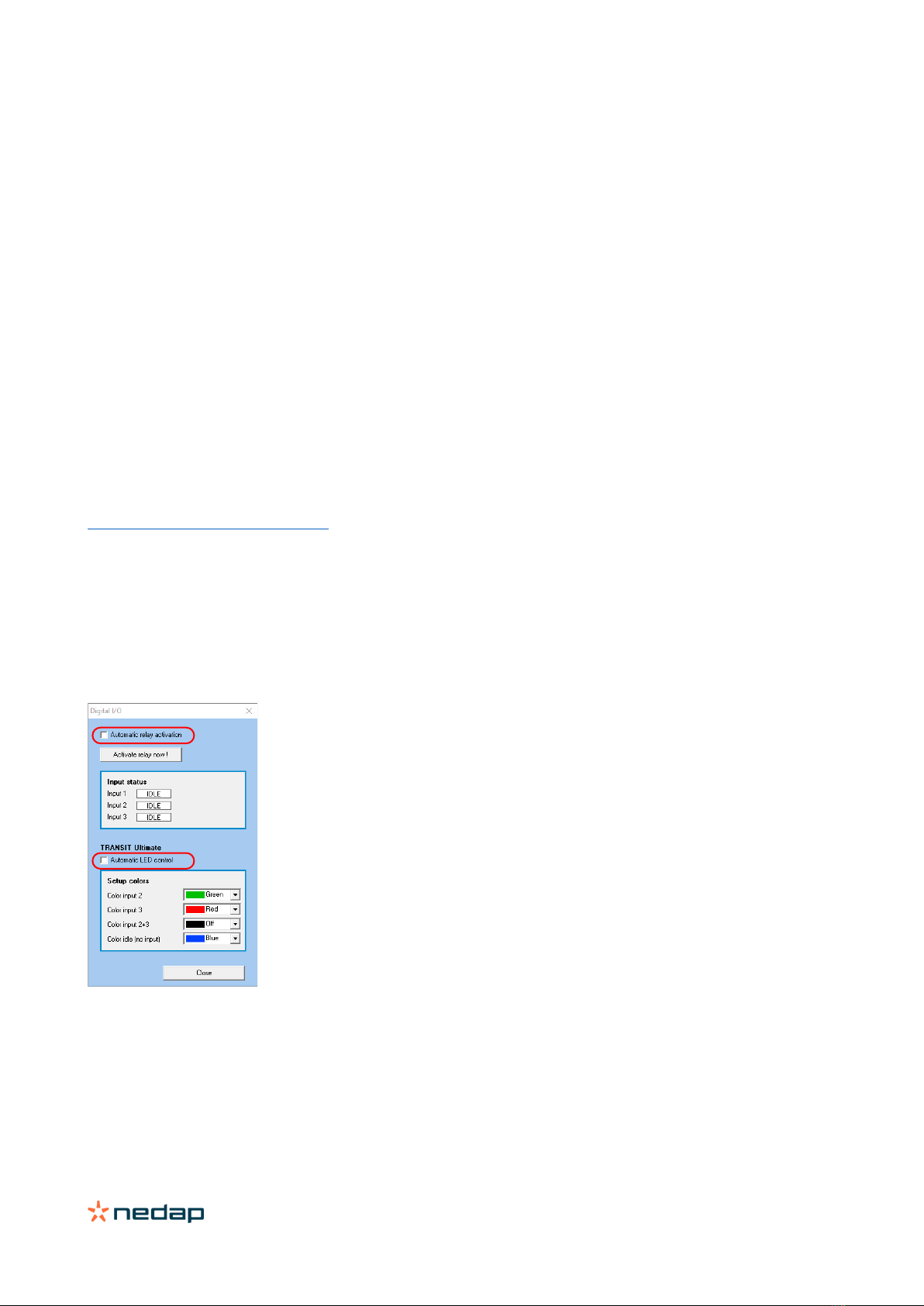
Configuration settings
The relay activation and LED control must both be set to manual mode.
This is best done using the NEDAP P81TEST software. Download this software from our partner portal
https://portal.nedapidentification.com.
Start NEDAP P81TEST software and connect to the reader using the USB or RS232 interface.
1. Click Options, Digital I/O.
2. Disable automatic relay activation.
3. Disable automatic LED control.
Figure 10: TRANSIT configuration for OSDP applications.

TRANSIT Ultimate | installation guide
16/
40
4Connections
4.1 Overview
Figure 11: TRANSIT Ultimate connections overview
Power supply
See chapter 4.2
Read-disable input
See chapter 4.4.2
General purpose inputs
See chapter 4.4.4
Proximity antenna
See chapter 4.5.1
Relay output
See chapter 4.4.1
Tamper switch
See chapter 4.4.3
Communication
See chapter 4.3
Antenna modulation
See chapter 4.5.2
TRANSIT Ultimate | installation guide
17/
40
4.2 Power supply
The TRANSIT Ultimate can be powered by AC mains or by a 24 VDC power supply.
4.2.1 AC mains
Connect the Mains load and neutral wires to the connector terminals VAC-L and VAC-N. The earth wire should be
connected to the dedicated safety ground connection.
Input voltage: 100 – 240 VAC
Frequency: 60 – 50 Hz
Figure 12: AC mains connections
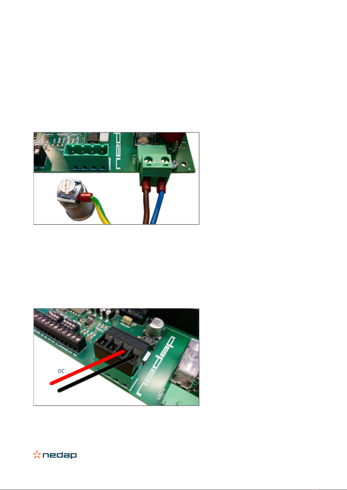
4.2.2 DC supply input
Connect the DC power supply to the connector terminals as indicated below.
Remove the connector for easy fixing the wires.
Input voltage: 24 VDC ± 10%
Max. input current: 700 mA @ 24 VDC
Figure 13: DC input connections
VAC-L
VAC-N
GROUND
GND
+24VDC
TRANSIT Ultimate | installation guide
18/
40
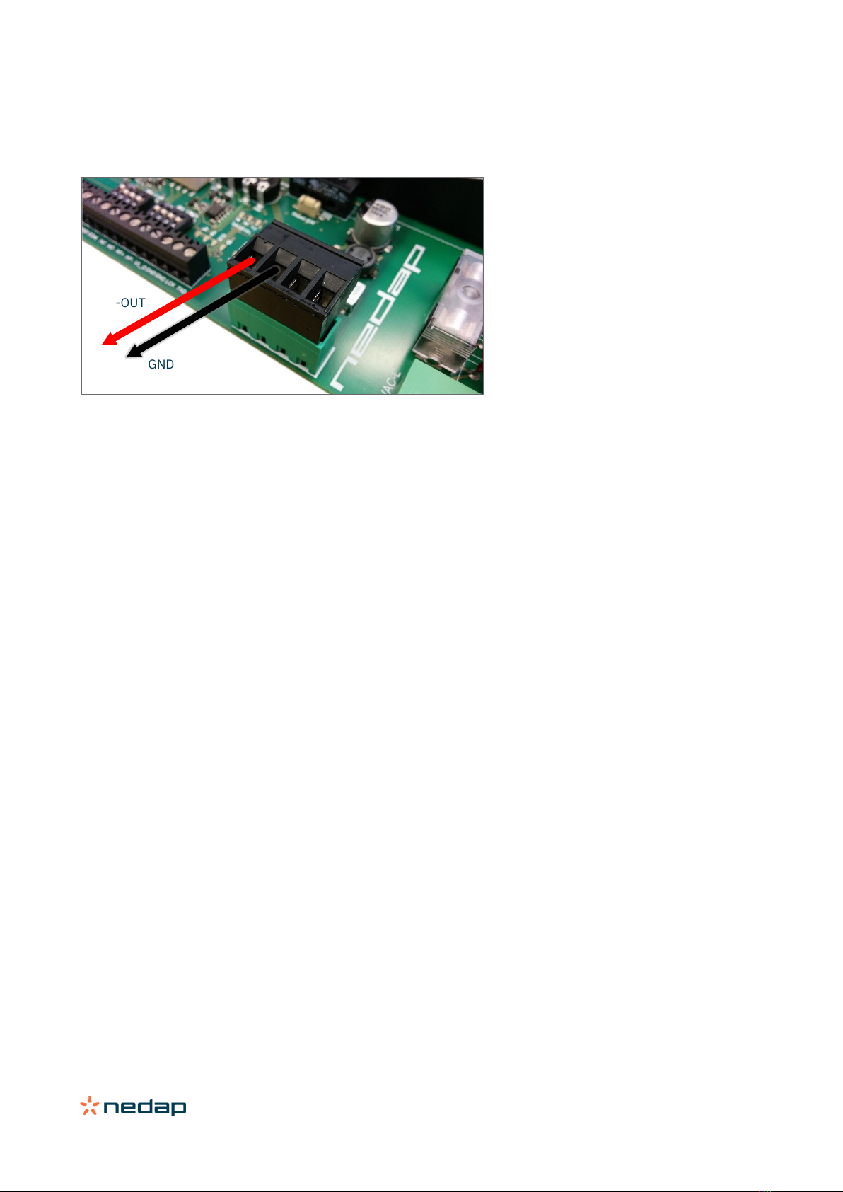
4.2.3 DC output
The DC output can be used to supply power to an additional device installed inside or near the TRANSIT Ultimate.
Figure 14: DC output connections
DC output ratings
Output voltage: 23.4 VDC ± 10%
Max. output current: 100 mA.
GND
+DC-OUT
TRANSIT Ultimate | installation guide
19/
40
4.3 Communication
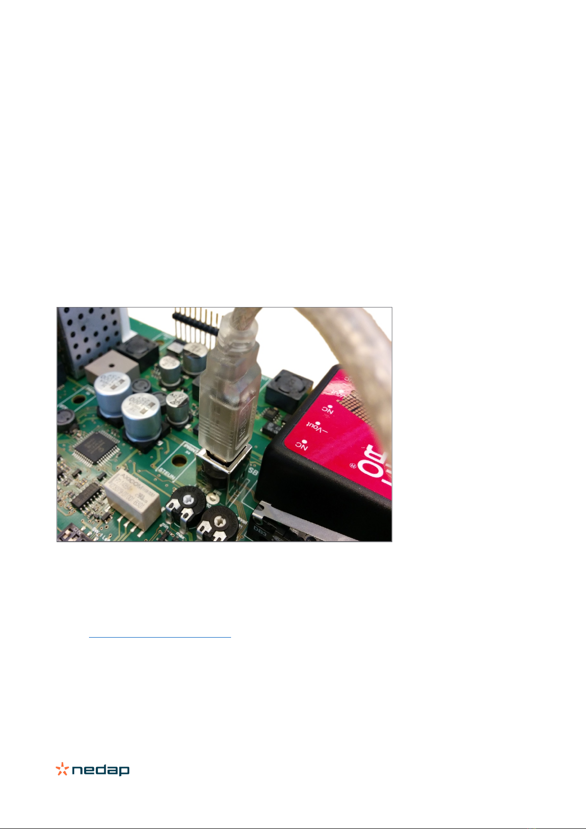
4.3.1 USB
The TRANSIT Ultimate features an USB interface for service and installation purposes. The USB connector (Type B) is
accessible behind the cover.
Note 1
While the USB interface is in use, the optional communication interface board is disabled.
Note 2:
While the USB cable is connected, it is not possible to read HID-PROX cards.
To fix this issue;
•Disconnect the USB cable
•Make sure the HID interface board is installed correctly
•Restart the TRANSIT Ultimate (or press reset button)
Figure 15: USB connection
USB driver installation
Make sure your computer is connected with internet. Connect the TRANSIT reader to your computer via the USB cable.
The USB drivers may be installed automatically. In case you need to install the USB drivers manually, please go to the
website www.ftdichip.com/Drivers/VCP.htm and download the VCP (Virtual Com Port) drivers. After successful
installation of the USB drivers the reader will appear in the Windows device manager in "Ports (COM & LPT)" section

TRANSIT Ultimate | installation guide
20/
40
4.3.2 Wiegand / Magstripe / Barcode
The Wiegand, Magstripe and Barcode interfaces share the same connections. The connections are described below.
The actual protocol output depends upon the reader firmware. Please refer to the firmware manual for more details.
Connections Wiegand Magstripe Barcode
O-1 - Card Loaded -
O-2 Data-0 (green) Clock -
O-3 Data-1 (white) Data Data
GND Ground (black) Ground Ground
The picture below illustrates the Wiegand wiring.
Figure 16: Wiegand wiring
Cable specification
4 x 0.25mm2 shielded
Maximum cable length 150 meter.
GND
O-2
O-3
Other manuals for Transit Ultimate
1
This manual suits for next models
1
Table of contents
Other Nedap RFID System manuals

Nedap
Nedap uPASS REACH User manual

Nedap
Nedap NVITE User manual

Nedap
Nedap TRANSIT Entry User manual

Nedap
Nedap MidRanger + Antenna Set User manual

Nedap
Nedap PROX-BOOSTER 2G User manual

Nedap
Nedap ANPR LUMO User manual

Nedap
Nedap VP1007-B User manual

Nedap
Nedap TRANSIT Entry User manual

Nedap
Nedap uPASS TARGET User manual

Nedap
Nedap uPASS Access User manual


