Nemo SCT Technical specifications

Nemo
Climatic sensor
SCT
WSCT
EN - Instructions and warnings for installation and use
IT - Istruzioni ed avvertenze per l’installazione e l’uso
FR - Instructions et avertissements pour l’installation et l’utilisation
ES - Instrucciones y advertencias para la instalación y el uso
DE - Installierungs-und Gebrauchsanleitungen und Hinweise
PL - Instrukcje i ostrzeżenia do instalacji i użytkowania
NL - Aanwijzingen en aanbevelingen voor installatie en gebruik
0682
WSCT
SCT


Quick reference guide
Nemo WSCT/ SCT
Step 1 - Installation and connections
Note • The numbering of the figures in
this Guide does not correspond to that
used in the full Instruction Manual. •
This Guide does not substitute the full
Instruction Manual.
Climatic
sensor
10
8
4
3
3
2
5679
11
60° max
60°60° 60°
1
10
EN
IST255R03_23-05-2013 1/4

IST255R03_23-05-20132/4
EN
Step 2 - Memorizing the sensor and confirming memorization
33
10
sec. Old
01 02 03
“P1”“P1”
X 3
“P1”
01 02
“P1”
2
sec. ON
OFF
Hold down Wait Release Press 3 times Press 1 time
10
8
4
3
3
2
5679
11
60° max
60°60° 60°
1
10
“Wind” sensor
(WSCT only)
Wind
(WSCT only)
Led “L1”
button “P1”
Sun
“Sun” sensor
photovoltaic power cell
Fig. A
Movements (3) / Sounds (3 beeps) Press 1 time ( Up) Press 1 time ( Stop)
(confirming
memorization)

Step 4 - Calibrating the “Wind” sensor (WSCT only)
3
sec.
01 02
wind
03 04 wind
...
...
2
sec. ON
OFF
Turn the trimmer to “Test” Actuate the blades Wait Up Series of flashes
Stop the blades Series of flashes Press 1 time ( Down) Turn trimmer to another value
“L1” (green-red-)
“L1” (red)
fast flashing
fast flashing
IST255R03_23-05-2013 3/4
Step 3 - Calibrating the “Sun” sensor
2
sec.
01 02
sun
03
klx
≥ 1Klux
sun
klx
...
...
Turn the trimmer to “Test” Illuminate the sensor Wait Down Series of flashes
“L1” (green)
fast flashing
Cover the sensor Series of flashes Up Oncover the sensor Turn the trimmer to another value
“L1” (green-red-)
fast flashing
EN

4 – English
EN
ENGLISH
GENERAL WARNINGS
IMPORTANT
• Important safety instructions: observe these in-
structions - improper installation can result in
serious injury.
• For personal safety it is important to observe
these instructions.
• Keep these instructions.
• All installation procedures, connections, pro-
gramming and maintenance of the product
must be performed exclusively by a qualified
technician!
• The sensor is not a safety device capable of
eliminating damage to the awning due to strong
winds (indeed, a simple power failure can pre-
vent the awning being automatically retracted).
The sensor is rather part of an automation ca-
pable of protecting the awning and facilitating
its use.
• The manufacturer is not responsible for damage due
to atmospheric events undetected by the device's
sensors.
• Do not open the device protection housing as it con-
tains non-serviceable electrical circuits.
• Never apply modifications to any part of the device.
Operations other than as specified can only cause
malfunctions. The manufacturer declines all liability
for damage caused by makeshift modifications to
the product.
• Never place the device near sources of heat and
never expose to naked flames. This may damage it
and cause malfunctions.
• The product is not intended for use by persons (in-
cluding children) with reduced physical, sensory or
mental capacities, nor by anyone with insufficient ex-
perience or familiarity.
• Make sure that children do not play with the product.
•The unit is solar powered. The photovoltaic cell must
be exposed to sunlight throughout the day; make
sure that its photosensitive surface is always clean
and unobstructed by leaves, snow or other matter:
clean it with a soft damp cloth, do not use alcohol,
benzene, solvents or other agents when cleaning it.
• Handle the product with care, making sure not to
crush, strike or drop it.
1 - PRODUCT DESCRIPTION AND INTENDED
USE
The product is a climatic sensor intended for use in au-
tomation systems for awnings, shutters, skylights, etc.
with Nice tubular motors and control units. Any other
use is to be considered improper and is strictly
prohibited! Nice declines all liability for damage
resulting from improper use of the product and
other than as specified in this manual. The sensor
has an integral radio transmitter and is solar powered;
at night it uses the charge stored up during the day, and
thus does not require a mains power connection. The
other components of the device are indicated in the
Quick reference guide (Step 1 - fig. A).
Product operation is based on real-time readings of
variations in wind speed (not present on SCT) and sun-
light intensity. When the climatic sensor readings vio-
late their thresholds (either above or below), the sensor
transmits a radio signal to the motor's automation re-
ceiver, which in turn activates an Up or Down manoeu-
vre, depending on the type of signal received (above or
below the threshold). Up to 3 sensors can be installed
on a single automation system, thus enabling data ac-
quisition at different points of the environment.
2 - PRELIMINARY INSTALLATION CHECKS
AND PRODUCT APPLICATION LIMITS
• Read the technical specifications provided in the
chapter “Product technical specifications” to check
the application limits of the sensor.
• The sensor may not be compatible with older motors
manufactured before June 2004 or with TT0 control
units.
• (fig. 1) In favourable conditions (unobstructed field),
the transmission range of the sensor is 100 m, how-
ever, since the sensor is intended to protect the
awning, it is advisable to install it at most 10-20 m
away from the motor. We also recommend check-
ing that the zone is clear of other wireless devices
transmitting on the same frequency, such as alarms,
wireless headsets, etc.: they can further reduce the
range or even block the transmissions of the device
to the motor.
• Make sure that the sensor's installation zone satisfies
the following requisites:
– (fig. 2) it must allow for full and direct sunlight ex-
posure of the sun sensor surface and the photovol-
taic power cell; never install the product in zones
subject to shade from awnings, trees, balconies etc.
or below a source of intense artificial light;
– (fig. 3) the area must ensure exposure of the wind
sensor blades (WSCT only) to the same ventilation as
that applied on the sun awning to be automated.
• Since the sensor's body is jointed and can be orient-
ed as desired, ti can also be installed to sloping sur-
faces. The tilt range is given in the Quick reference
guide (Step 1 - phase 1).
• Ensure that the surfaces selected for installation are
solid and guarantee a stable fixture.
• Make sure that the sensor is protected against ac-
cidental impact.

max
1
2
3
English – 5
EN

6 – English
EN
3 - PRODUCT INSTALLATION
For installation, fix the various parts of the product in
numerical order as shown in the Quick reference guide
(Step1). Then adjust the sensor body as shown in the
Quick reference guide (Step 1 - phase 1). For WSCT
model: make sure that the wind sensor blades are hori-
zontal (Quick reference guide - Step 1 - phase 11).
4 - MEMORIZING THE SENSOR IN THE MO-
TOR RECEIVER
As for any other transmitter, the climatic sensor's radio
code must be memorized in the receiver of the motor
it controls, so that the sensor can send wireless com-
mands. To memorise the sensor follow the “Mode I”
procedure described in the manual of the tubular mo-
tor or associated receiver. Alternatively the following
memorisation procedure can be used.
• Procedureformemorisingadditionaltransmit-
tersusinganalreadymemorisedtransmitter
Caution – This procedure (Quick reference guide -
Step 2) may only be used if one or more radio codes
have already been memorized in the tubular motor.
01. Caution! – Make sure that the “Sun” and “Wind”
trimmers (if the latter is present) are not set to
“Test”. Turn them to another value if necessary.
02. Hold down for 10 seconds button “P1” of the new
sensor.
03. Press the button of a previously memorized trans-
mitter 3 times (slowly).
04. Press the again the button “P1” of the sensor to be
memorized and check that the motor emits 3 sig-
nals(*) (= memorization successful). Note – If the
memory is full, the motor emits 6 signals(*), notify-
ing the user that memorisation of the new sensor
is not possible.
(*)Note – The signals may be beeps or small move-
ments (depending on the motor model).
• Checkingthatthesensorhasbeenmemorized
01. Shut off electrical power to the motor; wait for 2
seconds and restore power.
02. Send a command to the system and, while it is
executing, press sensor button P1 (yellow). Now,
check that the motor immediately stops (= sensor
memorized).
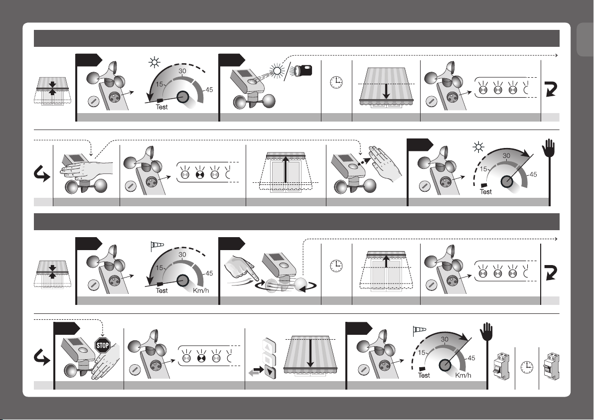
5 - CALIBRATING THE SENSORS
Once the sensors have been memorized, they must be
calibrated, as follows.
Note to the procedures – When the trimmer is set to
“Test”, the system sets the sensor threshold to a mini-
mum, so that it can react to events without the delays
employed in normal operation. This serves to quickly
check that the system is behaving properly.
• Calibratingthesunsensor(Quick reference guide
- Step 3)
01. Turn the “Sun” trimmer CCW to “Test”.
02. Illuminate the sun sensor with bright sunlight; if the
day is very cloudy, use a lamp. The brightness of
the light striking the sensor must be at least 1Klux.
03. Check that, after 2 seconds, the motor lowers the
awning and the green Led flashes briefly several
times (= threshold exceeded).
04. Now obscure the sun sensor with a hand or a
black cloth which lets no light through, and check:
a) the Led must flash alternately red and green
alternately briefly several times (= return to within
threshold); b) the sensor must tell the motor to
raise the awning.
05. Remove your hand or the cloth.
06. Now, turn the “Sun” trimmer CW to the desired
setting(*), outside the “Test” zone.
(*) - this value can be changed later with the procedure
and values given in chapter 6.
• Calibratingthewindsensor (function not available
on SCT model) (Quick reference guide - Step 4)
01. Turn the “Wind” trimmer CCW to “Test”.
02. Rotate the wind sensor blades and check: a) the
motor must raise the awning; b) the sensor must
prevent the motor receiving any other commands
(thus protecting the awning against the wind);
c) the Led must flash red briefly several times (=
threshold exceeded).
03. Now stop the blades and check: a) the Led must
flash briefly red and green alternately several times
(= return to within threshold); b) the sensor must
deactivate the protection function: send a trans-
mitter command to the motor, the awning should
respond.
04. Now, turn the “Wind” trimmer CW to the desired
setting(*), outside the “Test” zone.
(*) - this value can be changed later with the procedure
and values given in chapter 6.
6 - SETTING THE CLIMATIC SENSOR TRIP
VALUE
You must set the “trip value” of the climatic sensors,
i.e. a value above (or below) which the sensor trips and
sends a wireless command to the receiver in which it
is memorized.
Note - During normal operation of the sun and wind
sensors (if the latter is present), led “L1” is off, even
when the unit is transmitting control signals.
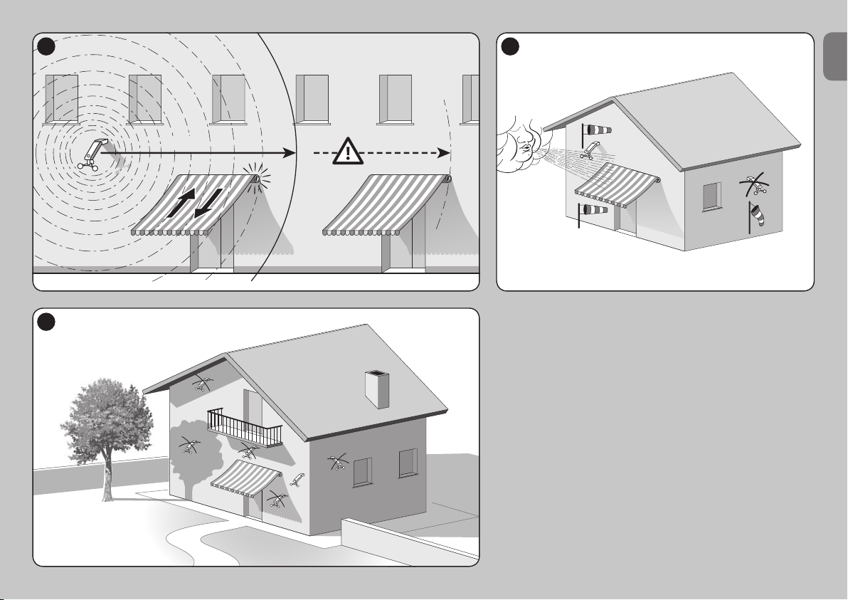
• Operation of the “WIND” setpoint (fig. 5) – The
wind sensor, only on WSCT model, measures the
windspeed in real time; when it exceeds the setpoint,
after 3 seconds the sensor transmits the Up command
to the motor and blocks manual controls.
When the windspeed drops below the setpoint, after 4
minutes the sensor sends a signal to the motor, thus
releasing it to receive manual commands. After 10 min-
utes (about) automatic operation is restored.
• Operation of the “SUN” setpoint (fig. 6) – The sun
sensor measures the brightness of the sunlight in real
time; when it exceeds the setpoint, after 2 minutes the
sensor sends the Down command to the motor.
When the brightness drops below the setpoint value,
after 15 minutes the sensor sends the Up command
to the motor.

English – 7
EN
Setting the “Sun” and “Wind” sensor setpoints
(fig. 4)
01. Turn the “Sun” trimmer to the desired setting.
Important – Setting the trimmer to its maximum
value (at the end of its CW rotation) disables the
Sun sensor.
02. Turn the “Wind” trimmer to the desired setting (if
present).
03. Make sure that Led “L1” flashes red and green al-
ternately.
04. To terminate the procedure, wait for the flashing to
stop.
7 - DIAGNOSTICS
You can enable “DIAGNOSTICS mode” at any time to
check whether the weather conditions at the time are
above or below the setpoint values and to identify mal-
functions.
To enable diagnostics, press “P1” briefly and wait 1
second for the red Led to stop flashing. Now watch
the Led and check the sequences of flashes against
Table A. Note – If several thresholds are exceeded
during normal operation (for example, wind and rain to-
gether), the diagnostics signals only the one which has
the lower number in Table A.
Caution! – Diagnostics mode can only be used for
reading signals off the Leds, not for operating the
awning.
Note – To check whether the device is really faulty,
simply run the calibration procedures given in chap-
ter 5.
8 - BASIC TROUBLESHOOTING
If the wind or sunlight are stronger than their re-
spective trip values but the motor does not re-
spond as it should, check that the sensor is powered
correctly and memorized in the motor's receiver (see
chapters 3 and 4). If this does not solve the problem,
check the operation of the sensor by running the diag-
nostics described in chapter 7.
PRODUCT DISPOSAL
• This product is an integral part of the automation
and must therefore be scrapped together with it, in the
same way as indicated in the automation's instruction
manual. • Dispose of the product packaging material in
compliance with established local legislation.
2
sec.
01 02
ON
OFF
sun
klx
03 04
Km/h
wind
...
4
Off Wait Desired value... Desired value... (WSCT model) On Series of flashes
“L1” (green-red-)
fast flashing
Table A - Led diagnostics signals
1Red Led on(*) (for 3 seconds) = The wind
setpoint has been exceeded
2Green Led on (for 3 seconds) = The sun
setpoint has been exceeded
3
Red Led flashing(*) (0.5 second intervals for
3 seconds) = Self-test: wind sensor fault. The
sensor has not detected variation in the wind
speed in the last 24 hours
4
Green Led flashing (for 3 seconds) = Self-
test: sun sensor fault. The sensor has not
detected variation in the sunlight in the last
24 hours
5Led off = No setpoint exceeded
(*) = Not present on SCT model

8 – English
EN
EC DECLARATION OF CONFORMITY
Nice S.p.A. hereby declares that the products:
Nemo WSCT, Nemo SCT are compliant with
the essential requisites and other pertinent provi-
sions of directive 1999/5/CE. The CE declara-
tion of conformity can be viewed and printed out
at www.niceforyou.com or may be requested
directly form Nice S.p.A.
Mr. Luigi Paro
(Managing Director)
TECHNICAL CHARACTERISTICS OF THE
PRODUCT
■Power: completely autonomous solar power with
64 mWp photovoltaic cell
■ Frequency: 433.92 MHz with integral antenna
■ Radiated power(*): approx. 1 mW (erp). In optimal
conditions this corresponds to a range of approx. 100
m in open field or 20 m inside buildings.
■ Protection rating: IP 44
■ Operating temperature: - 20°C to + 55°C
■ Dimensions mm: (volume) 125 x 250 x 100 (H)
■ Weight: WSCT: 250 g; SCT: 230 g
•“Sun”sensor
■ Range: 3 to 80 klux
■ Setting: 5 to 60 klux
■ Self-test: after 24 h without brightness variation
•“Wind”sensor (WSCT only)
■ Range: 0 to 125 kph
■ Conversion factor: 0.26 rpm - kph
■ Setting: 5 to 80 kph
■ Self-test: after 24 h without wind
–––––––
Notesontechnicalspecifications:
– (*) The transmitter's range may be affected by other
devices operating nearby and at the same frequency
(e.g. wireless headsets, alarm systems, etc.), which
interfere with it. In the event of strong interference,
Nice cannot guarantee the effective range of their de-
vices.
– All technical specifications stated herein refer to an
ambient temperature of 20° C (± 5° C).
– Nice S.p.A. reserves the right to apply modifications
to the product at any time when deemed necessary,
maintaining the same intended use and functionality.

Guida rapida
Nemo WSCT/ SCT
Passo 1 - Installazione e Collegamenti elettrici
Nota alla consultazione • In questa
Guida rapida la numerazione delle fig-
ure è autonoma e non corrisponde alla
nu merazione citata nel testo del Manu-
ale completo. • Questa guida non sos-
tituisce il Manuale completo.
Climatic
sensor
10
8
4
3
3
2
5679
11
60° max
60°60° 60°
1
10
IT
IST255R03_23-05-2013 1/4

IT
IST255R03_23-05-20132/4
Passo 2 - Memorizzazione del sensore e verifica della memorizzazione
10
8
4
3
3
2
5679
11
60° max
60°60° 60°
1
10
sensore Vento
(solo per WSCT)
Vento
(solo per
WSCT)
Led “L1”
tasto “P1”
Sole
sensore Sole
cella fotovoltaica
Fig. A
33
10
sec. Old
01 02 03
“P1”“P1”
X 3
“P1”
01 02
“P1”
2
sec. ON
OFF
Mantenere premuto Attendere Rilasciare Premere 3 volte Premere 1 volta
Movimenti (3) / Suoni (3 beep) Premere 1 volta (Salita) Premere 1 volta (Stop manovra)
(verifica della
memorizzazione)

Passo 4 - Taratura del sensore “Vento” (solo per il modello WSCT)
3
sec.
01 02
wind
03 04 wind
...
...
2
sec. ON
OFF
Ruotare trimmer su “Test” Azionare le pale Attendere Salita Serie di lampeggi
Fermare le pale Serie di lampeggi Premere 1 volta (Discesa) Ruotare trimmer su altro valore
“L1” (verde-rosso-)
“L1” (rosso)
lampeggi veloci
lampeggi veloci
Passo 3 - Taratura del sensore “Sole”
2
sec.
01 02
sun
03
klx
≥ 1Klux
sun
klx
...
...
Ruotare trimmer su “Test” Illuminare il sensore Attendere Discesa Serie di lampeggi
“L1” (verde)
lampeggi veloci
Coprire il sensore Serie di lampeggi Salita Scoprire il sensore Ruotare trimmer su altro valore
“L1” (verde-rosso-)
lampeggi veloci
IT
IST255R03_23-05-2013 3/4

4 – Italiano
IT
AVVERTENZE GENERALI
ATTENZIONE!
• Istruzioni importanti per la sicurezza: attenersi
alle istruzioni in quanto un’installazione impro-
pria può provocare gravi ferite.
• Per la sicurezza delle persone è importante ri-
spettare queste istruzioni.
• Conservare queste istruzioni.
• Tutte le operazioni di installazione, di collega-
mento, di programmazione e di manutenzione
del dispositivo devono essere effettuate esclu-
sivamente da un tecnico qualificato!
• Il sensore non è da considerarsi un dispositi-
vo di sicurezza che elimina i guasti alla tenda
per effetto del vento forte (di fatto, un banale
blackout elettrico renderebbe impossibile il riti-
ro automatico della tenda). Il sensore va consi-
derato parte di un’automazione utile alla salva-
guardia della tenda e al confort per il suo uso.
• Il produttore declina ogni responsabilità per i danni
materiali che dovessero verificarsi a causa di eventi
atmosferici non rilevati dai sensori del dispositivo.
•
Non aprire il guscio di protezione del dispositivo perchè
contiene circuiti elettrici non soggetti a manutenzione.
• Non eseguire modifiche su nessuna parte del dispo-
sitivo. Operazioni non permesse possono causare
solo malfunzionamenti. Il costruttore declina ogni re-
sponsabilità per danni derivanti da modifiche arbitra-
rie al prodotto.
• Non mettere il dispositivo vicino a fonti di calore né
esporlo a fiamme libere. Tali azioni possono danneg-
giarlo ed essere causa di malfunzionamenti.
• Il prodotto non è destinato ad essere usato da per-
sone (bambini compresi) le cui capacità fisiche, sen-
soriali o mentali siano ridotte, oppure con mancanza
di esperienza o di conoscenza.
•
Controllare che bambini non giochino con il prodotto.
•Il dispositivo è alimentato da una cella fotovoltaica.
Poiché nelle ore diurne questa deve essere esposta
costantemente alla luce solare, assicurarsi che la sua
superficie sensibile sia sempre pulita e libera da fo-
glie, neve o altro: pulire la superficie con un panno
morbido e umido, evitando sostanze contenenti al-
cool, benzene, diluenti o similari.
• Maneggiare con cura il prodotto evitando azioni che
possano danneggiarlo come, ad esempio, schiac-
ciamenti, urti, cadute, eccetera.
1 - DESCRIZIONE DEL PRODOTTO E DESTI-
NAZIONE D’USO
Il presente prodotto è un sensore climatico destina-
to agli impianti di automatizzazione per tende da sole,
tapparelle, lucernari e similari, che adottano centrali e
motori tubolari Nice. Ogni altro uso è da conside-
rarsi improprio e vietato! Nice non risponde dei
danni risultanti da un uso improprio del prodotto,
diverso da quanto previsto nel presente manuale.
Il sensore è dotato di un trasmettitore radio integrato e
di un’alimentazione autonoma a energia solare, fornita da
una cella fotovoltaica integrata; durante la notte il senso-
re sfrutta l’energia residua accumulata di giorno, senza la
necessita, dunque, di essere collegato alla rete elettrica.
Le altre parti che compongono il dispositivo sono indi-
cate nella Guida rapida (Passo 1 - fig. A).
Il funzionamento del prodotto si basa sul rilevamento
in tempo reale della velocità del vento (funzione assen-
te nel modello SCT) e dell’intensità della luce solare.
Quando il valore rilevato dai sensori climatici supera
(verso l’alto o verso il basso) la soglia d’intervento
impostata, il sensore trasmette un “segnale radio” al
ricevitore del motore, che a sua volta, comanda una
manovra di Salita o di Discesa, in base al tipo di segna-
le ricevuto (sopra o sotto la soglia). In un’automazione
possono essere installati fino a 3 sensori: questo con-
sente di controllare più punti nell’ambiente.
2 - VERIFICHE PRELIMINARI ALL’INSTALLA-
ZIONE E LIMITI D’IMPIEGO DEL PRODOTTO
• Leggere i dati tecnici riportati nel capitolo “Caratteri-
stiche tecniche del prodotto” per valutare i limiti d’im-
piego del sensore.
• Il sensore potrebbe non essere compatibile con i
vecchi motori prodotti prima del giugno 2004 oppu-
re con le Centrali di comando TT0.
•
(fig. 1) Anche se in condizioni favorevoli (cioè in cam-
po aperto) la portata radio del sensore è in grado di
arrivare fino a 100 m, considerando che il sensore
rappresenta una protezione per la tenda, si consi-
glia di installare il sensore a una distanza massima di
10-20 m dal motore. Inoltre si consiglia di accertarsi
che nella zona non vi siano altri dispositivi radio che
trasmettano alla stessa frequenza come, ad esem-
pio, allarmi, radiocuffie, eccetera: l’azione di questi
dispositivi potrebbe ridurre ulteriormente la portata o
addirittura bloccare la comunicazione tra il sensore e
il motore.
• Accertarsi che il luogo prescelto per l’installazione
del sensore abbia i seguenti requisiti:
– (fig. 2) deve permettere l’insolazione piena e diretta
della superficie del sensore sole e della cella fotovol-
taica che alimenta il prodotto; non installare il prodot-
to nelle zone d’ombra create da tende, alberi, balco-
ni ecc. o sotto una sorgente artificiale di luce intensa;
– (fig. 3) deve permettere l’esposizione delle pale del
sensore vento (solo per il modello WSCT) alla stessa
ventilazione a cui è soggetta la tenda da sole che si
Istruzioni originali
ITALIANO

max
1
2
3
Italiano – 5
IT

6 – Italiano
IT
desidera automatizzare.
• Poiché il corpo del sensore è snodato e orientabile,
è possibile fissare il prodotto anche su una superficie
inclinata. I limiti dell’inclinazione sono riportati nella
Guida rapida (Passo 1 - fase 1).
• Accertarsi che la superficie prescelta per l’installazio-
ne sia di materiale solido e possa garantire un fissag-
gio stabile.
• Accertarsi che il sensore sia collocato in una posizio-
ne protetta da urti accidentali.
3 - INSTALLAZIONE DEL PRODOTTO
Per eseguire l’installazione, fissare le varie parti del pro-
dotto seguendo l’ordine numerico riportato nella Guida
rapida (Passo 1). Infine orientare il corpo del sensore
come mostrato nella Guida rapida (Passo 1 - fase 1).
Per il modello WSCT: accertarsi che le pale del senso-
re vento siano su un piano orizzontale (Guida rapida -
Passo 1 - fase 11).
4 - MEMORIZZAZIONE DEL SENSORE NEL
RICEVITORE DEL MOTORE
Come per qualsiasi trasmettitore, anche per il presen-
te sensore climatico è necessario memorizzare il suo
codice radio nel ricevitore del motore da comandare,
in modo che il sensore possa inviare i comandi “via ra-
dio”. Per memorizzare il sensore occorre utilizzare la
procedura “Modo I” descritta nel manuale del moto-
re tubolare o del ricevitore abbinato. In alternativa è
possibile usare anche la seguente procedura di me-
morizzazione.
•
Proceduradimemorizzazionediulterioritra-
smettitoriconuntrasmettitoregiàmemorizzato
Avvertenza – Questa procedura (Guida rapida - Pas-
so 2) può essere usata soltanto se nel motore tubolare
sono già memorizzati uno o più codici radio.
01. Attenzione! – Accertarsi che i trimmer “Sole” e
“Vento” (se quest’ultimo è presente) non siano po-
sizionati sul valore “Test”. Eventualmente ruotarli
su un altro valore.
02. Mantenere premuto per 10 secondi il tasto “P1”
del nuovo sensore da memorizzare.
03. Premere per 3 volte (lentamente) il tasto di un vec-
chio trasmettitore già memorizzato nel motore.
04. Premere di nuovo il tasto “P1” del sensore da me-
morizzare e accertarsi che il motore emetta 3 se-
gnalazioni(*) (= memorizzazione avvenuta). Avver-
tenza – Se la memoria è piena, il motore emette
6 segnalazioni(*) che indicano l’impossibilità di me-
morizzare il nuovo sensore.
(*)Nota – Le segnalazioni possono essere dei suo-
ni (beep) oppure dei piccoli movimenti (dipendono dal
modello del motore).
• Verificadell’avvenutamemorizzazionedelsen-
sore
01. Togliere l’alimentazione elettrica al motore; atten-
dere 2 secondi e ridare l’alimentazione.
02. Comandare una manovra e, durante la sua ese-
cuzione, premere il tasto P1 (giallo) sul sensore.
Quindi, accertarsi che il motore arresti immediata-
mente la manovra (= sensore memorizzato).
5 - TARATURA DEI SENSORI
Al termine della procedura di memorizzazione è neces-
sario tarare i sensori effettuando le seguenti procedure.
Nota alle procedure – Quando il trimmer è posizio-
nato sulla funzione “Test” il sistema imposta la soglia
del sensore al minimo, in modo che quest’ultimo rea-
gisca agli eventi in tempo reale, senza rispettare i tem-
pi di attesa previsti per il funzionamento normale. Ciò
permette di verificare velocemente il comportamento
del sistema.
•
Taraturadelsensoresole(Guida rapida - Passo 3)
01. Ruotare il trimmer “Sole” in senso antiorario, fino a
raggiungere la posizione “Test”.
02. Fare in modo che il sensore sole venga illuminato
dalla luce solare intensa; se il cielo è particolar-
mente nuvoloso e coperto, utilizzare una lampada.
In ogni caso, l’intensità della luce deve essere di
almeno 1Klux.
03. Accertarsi che, dopo 2 secondi, il motore comandi
la Discesa della tenda e che il Led verde emetta
una serie di lampeggi brevi (= superamento della
soglia).
04. Quindi, oscurare il sensore sole con una mano o
con un telo nero opaco alla luce e accertarsi che:
a) che il Led esegua una serie di lampeggi brevi di
colore rosso e verde alternati (= fine superamento
soglia); b) che il sensore invii al motore un coman-
do di Salita.
05. Rimuovere la mano o il telo utilizzati per oscurare il
sensore.
06. Infine, ruotare il trimmer “Sole” in senso orario,
portandolo su un valore desiderato(*), fuori dalla
zona “Test”.
(*) - Questo valore è modificabile in un secondo mo-
mento utilizzando la procedura e le informazioni ripor-
tate nel capitolo 6.
• Taraturadelsensorevento(funzione assente nel
modello SCT) (Guida rapida - Passo 4)
01. Ruotare il trimmer “Vento” in senso antiorario, fino
a raggiungere la posizione “Test”.
02. Mettere in movimento le pale del sensore vento e
accertarsi che: a) il motore comandi la Salita del-
la tenda; b) che il sensore blocchi la possibilità di
comandare il motore con qualsiasi altro comando
(protezione della tenda dal vento); c) che il Led
emetta una serie di lampeggi brevi di colore rosso
(= superamento della soglia).
03. Quindi, fermare le pale e accertarsi che: a) il Led
emetta una serie di lampeggi brevi di colore ros-
so e verde alternati (= fine superamento soglia); b)
che il sensore sblocchi la protezione della tenda
dal vento: a tal proposito, dare un comando con
il trasmettitore e verificare che la tenda risponda a
questo comando.
04. Infine, ruotare il trimmer “Vento” in senso orario,
portandolo su un valore desiderato(*), fuori dalla
zona “Test”.

Italiano – 7
IT
(*) - Questo valore è modificabile in un secondo mo-
mento utilizzando la procedura e le informazioni ripor-
tate nel capitolo 6.
6 - IMPOSTAZIONE DELLE SOGLIE DI INTER-
VENTO DEI SENSORI CLIMATICI
La regolazione dei sensori climatici presenti nel pro-
dotto serve per impostare in ciascuno di loro la “so-
glia d’intervento”, ovvero un valore desiderato al di
sopra del quale (o al di sotto del quale) il sensore inter-
viene inviando un segnale radio al ricevitore nel quale
è memorizzato.
Nota - Durante il normale funzionamento del sensore
sole e del sensore vento (se quest'ultimo è presente) il
Led "L1" rimane sempre spento, anche nei momenti in
cui il dispositivo trasmette i comandi.
• Funzionamento della soglia “VENTO” (fig. 5) – Il
sensore vento, presente solo nel mod. WSCT, rileva
e misura in tempo reale la velocità del vento; quan-
do questa supera il valore impostato, dopo 3 secondi
il sensore trasmette al motore il comando di Salita e
blocca i comandi manuali.
Quando l’azione del vento termina e scende sotto il va-
lore impostato, dopo 4 minuti il sensore trasmette que-
sta condizione al motore, ripristinando la possibilità di
inviare i comandi manuali. Dopo 10 minuti (circa) viene
ripristinato il funzionamento automatico.
• Funzionamento della soglia “SOLE” (fig. 6) – Il
sensore sole rileva e misura in tempo reale l’intensità
della luce solare; quando questa supera il valore impo-
stato, dopo 2 minuti il sensore trasmette al motore il
comando di Discesa.
Quando l’intensità della luce solare scende sotto il va-
lore impostato, dopo 15 minuti il sensore trasmette al
motore il comando di Salita.
Procedura per impostare la soglia di intervento
del sensore “Sole” e “Vento” (fig. 4)
01. Ruotare il trimmer “Sole” fino a posizionarlo sul va-
lore desiderato. Importante – Se il trimmer viene
impostato sul valore massimo (cioè al termine della
corsa, procedendo in senso orario), viene escluso
il funzionamento del sensore sole.
02. Se è presente il trimmer “Vento”, ruotarlo fino a po-
sizionarlo sul valore desiderato.
03. Accertarsi che il Led “L1” emetta dei lampeggi ros-
si e verdi alternati.
04. Per terminare la procedura attendere la fine di que-
sti lampeggi.
7 - DIAGNOSTICA
In qualsiasi momento è possibile attivare la “modalità
DIAGNOSTICA” per verificare se l’intensità del feno-
meno atmosferico che si sta manifestando in quell’i-
stante è al di sotto o al di sopra della soglia impostata
2
sec.
01 02
ON
OFF
sun
klx
03 04
Km/h
wind
...
4
Spegnere
Attendere
Valore desiderato... Valore desiderato... (modello WSCT) Accendere Serie di lampeggi
“L1” (verde-rosso-)
lampeggi veloci
Tabella A - Segnalazioni diagnostiche del Led
1Led rosso acceso(*) (per 3 secondi) = È sta-
ta superata la soglia d’intervento “vento”
2Led verde acceso (per 3 secondi) = È stata
superata la soglia d’intervento “sole”
3
Led rosso lampeggiante(*) (intervalli di 0,5
secondi, per 3 secondi) = Auto-diagnostica:
guasto al sensore “vento”. Il sensore non ha
rilevato variazioni nella velocità del vento, nelle
ultime 24 ore
4
Led verde lampeggiante (per 3 secondi) =
Auto-diagnostica: guasto al sensore “sole”.
Il sensore non ha rilevato variazioni di intesità
nella luce solare, nelle ultime 24 ore
5Led spento = Non è stata superata nessuna
soglia d’intervento
(*) = Segnalazioni assenti nel modello SCT

8 – Italiano
IT
e per individuare eventuali guasti.
Per attivare la diagnosi premere brevemente il tasto
“P1” e attendere circa 1 secondo che il Led rosso
smetta di lampeggiare. Quindi osservare la successiva
segnalazione del Led e leggerne il significato nella Ta-
bella A. Nota – Se durante il normale funzionamento
vengono superate più soglie (ad esempio quella del
vento e quella della pioggia), il sistema diagnostico
segnala tra queste solo quella che nella Tabella A è
identificata con il numero più basso.
Attenzione! – La modalità “diagnostica” provoca
solo la segnalazione sul Led e non il comando
della tenda.
Nota – Per verificare se esiste realmente un guasto nel
dispositivo, è sufficiente eseguire le procedure di tara-
tura riportate nel capitolo 5.
8 - COSA FARE SE...
Se l’intensità del vento o della luce solare è su-
periore alla soglia impostata ma il motore sembra
non eseguire le manovre come dovrebbe, verifica-
re che il sensore sia alimentato correttamente e che
sia memorizzato correttamente nel ricevitore del moto-
re da comandare (vedere il capitolo 3 e 4). Se questo
non risolve il problema, controllare il corretto funzio-
namento del sensore eseguendo la diagnosi riportata
nel capitolo 7.
SMALTIMENTO DEL PRODOTTO
• Questo prodotto è parte integrante dell’automazione,
e dunque, deve essere smaltito insieme con essa, ap-
plicando gli stessi criteri riportati nel manuale istruzio-
ni dell’automazione. • Il materiale dell’imballaggio del
prodotto deve es sere smaltito nel pieno rispetto della
normativa presente a livello locale.
DICHIARAZIONE CE DI CONFORMITÀ
Con la presente, Nice S.p.A. dichiara che i pro-
dotti: Nemo WSCT, Nemo SCT sono confor-
mi ai requisiti essenziali ed alle altre disposizioni
pertinenti, stabilite dalla direttiva 1999/5/CE. La
dichiarazione di conformità CE può essere con-
sultata e stampata nel sito www.niceforyou.com
oppure può essere richiesta a Nice S.p.A.
Ing. Luigi Paro
(Amministratore delegato)
CARATTERISTICHE TECNICHE DEL PRODOTTO
■ Alimentazione: completamente autonoma, fornita
da una cella fotovoltaica integrata, da 64 mWp
■ Frequenza: 433,92 MHz con antenna integrata
■ Potenza irradiata(*): circa 1 mW (erp). In condizio-
ni ottimali corrisponde ad una portata di circa 100 m in
campo aperto o 20 m all’interno di edifici
■ Grado di protezione: IP 44
■ Temperatura di utilizzo: da - 20°C a + 55°C
■ Dimensioni mm: (volume) 125 x 250 x 100 (H)
■ Peso: WSCT: 250 g; SCT: 230 g
Sensore“Sole”
■ Gamma di misura: da 3 a 80 klux
■ Regolazione soglia: da 5 a 60 klux
■ Auto-diagnostica: dopo 24 h senza variazione
della luce
Sensore“Vento” (solo per il mod. WSCT)
■ Gamma di misura: da 0 a 125 km/h
■ Costante di conversione: 0,26 giri/s - km/h
■ Regolazione soglia: da 5 a 80 km/h
■ Auto-diagnostica: dopo 24 h senza vento
–––––––
Noteallecaratteristichetecniche:
– (*) La portata dei trasmettitori può essere influenza-
ta da altri dispositivi che operano nelle vicinanze alla
stessa frequenza del trasmettitore (ad esempio radio-
cuffie, sistemi di allarme, ecc.), provocando interfe-
renze con il ricevitore. Nei casi di forti interferenze,
Nice non può offrire nessuna garanzia circa la reale
portata dei propri dispositivi radio.
– Tutte le caratteristiche tecniche riportate, sono riferite
ad una temperatura ambientale di 20°C (± 5°C).
– Nice S.p.a. si riserva il diritto di apportare modifiche al
prodotto, in qualsiasi momento lo riterrà necessario,
mantenendone la stessa destinazione d’uso e le fun-
zionalità.

Guide rapide
Nemo WSCT/ SCT
Étape 1 - Installation et câblage
Note pour la consultation • Dans ce
guide rapide, le numérotage des figures
est autonome et ne correspondent pas
au numérotage cité dans le texte du
manuel complet. • Ce guide ne rem-
place pas le manuel complet.
Climatic
sensor
10
8
4
3
3
2
5679
11
60° max
60°60° 60°
1
10
FR
IST255R03_23-05-2013 1/4

FR
IST255R03_23-05-20132/4
Étape 2 - Mémorisation du capteur et vérification de la mémorisation
33
10
sec. Old
01 02 03
“P1”“P1”
X 3
“P1”
01 02
“P1”
2
sec. ON
OFF
Maintenir appuyé Attendre Relâcher Appuyer 3 fois Appuyer 1 fois
10
8
4
3
3
2
5679
11
60° max
60°60° 60°
1
10
capteur vent
(uniquement pour
WSCT)
Vent
(uniquement
pour WSCT)
Led « L1 »
touche « P1 »
Soleil
capteur soleil
cellule photovoltaïque
Fig. A
Mouvements (3) / Sons (3 bips) Appuyez 1 fois ( Montée) Appuyez 1 fois ( Arrêt manœuvre)
(vérification de
la mémorisation)
This manual suits for next models
1
Table of contents
Languages:
Popular Accessories manuals by other brands

WIKA
WIKA MH-3 operating instructions

Warmup
Warmup CDP-2 installation instructions

Setra Systems
Setra Systems 256 installation guide

Bitspower
Bitspower Griffin 120 Fan instruction manual

SUTO
SUTO S220 Instruction and operation manual

Audioaccess
Audioaccess DBM21 Software Programming and Hardware Connecting Guide