Neomeris Testomat 2000 Technical specifications

1
Testomat 2000®
Testomat ECO®
Maintenance Instructions

Contents
2
Contents
Contents...............................................................................................2
Important safety information .............................................................3
Qualification of the staff ........................................................................3
Warning notices in these instructions ...................................................3
Further documents................................................................................4
General instructions...........................................................................4
Testomat2000®in steam boiler plants with BOB operation: ................5
Prior to carrying out maintenance work ................................................6
Permissible tools...................................................................................6
Carrying out maintenance..................................................................7
Cleaning the measuring chamber and the sight-glass windows...........7
Cleaning the receiver optics..................................................................7
Cleaning the filter housing ....................................................................8
Cleaning the housing ............................................................................8
Removing and installing the measuring chamber holder......................9
Re-adjusting the measuring chamber holder (Overflow detection) .....9
Replacing the EPROM (software update)...........................................10
Opening the factory programming ......................................................10
Installing the interface cards SK910, UK910, RS910 (only Testomat
2000®) .................................................................................................11
Position and function of the fuses.......................................................12
Repairing or replacing the dosing pump.............................................14
Checking dosing .................................................................................15
Special function “Adjust mode”......................................................15
Testing of the overflow detection........................................................16
Checking the automatic adjustment....................................................16
Water consumption ..........................................................................17
Indicator consumption .....................................................................17
Indicator TH2025, TH2100, TH2250...................................................18
Indicator TH2005 ................................................................................18
Manual measured value check........................................................19
Troubleshooting................................................................................20
Error message MST analysis..............................................................20
Switching on the real-time clock (only Testomat2000®).....................22
Low water level ...................................................................................22
Error message FST optics (Testomat 2000®).....................................23
Error message MST turbid..................................................................23
Error message Ff outlet to drain .........................................................23
Error due to defective hardware .........................................................23
Readjusting the current interface........................................................24
Spare parts lists ..................................................................................25
Component positions.......................................................................26
Check List Testomat 2000®................................................................29
Product overview Testomat 2000®-Instruments ............................32

Important safety information
3
Important safety information
Please read the operating instructions and maintenance instruc-
tions carefully and completely prior to carrying out maintenance
work at Testomat instruments.
Observe the warning notices in these maintenance instructions
and the operating instructions of the respective instrument.
Always adhere to hazard warnings and safety tips when using
reagents, chemicals and cleaning agents. Please adhere to the re-
spective safety data sheet! Download the safety data sheets for
the supplied reagents at http://www.heyl.de.
Qualification of the staff
Maintenance work requires fundamental electrical and process engi-
neering knowledge as well as knowledge of the respective technical
terms. Assembly and commissioning should therefore only be carried
out by a specialist or by an authorised individual supervised by a
specialist.
A specialist is someone who due to his/her technical training, know-
how and experience as well as knowledge of relevant regulations can
assess assigned tasks, recognise potential hazards and ensure ap-
propriate safety measures. A specialist should always adhere to the
relevant technical regulations.
Warning notices in these instructions
The warning notices in these instructions warn the user about poten-
tial dangers to individuals and property resulting from incorrect han-
dling of the instrument. The warning notices are structured as follows:
Description of the type or source of danger
Description of the consequences resulting from non-observance
Preventive measures. Always adhere to these preventive
measures.
“DANGER” indicates an immediate hazardous situation which, if not
avoided, will result in death or serious injury.
“WARNING” indicates a potentially hazardous situation which, if not
avoided, could result in death or serious injury.
“CAUTION” indicates a potentially hazardous situation which, if not
avoided, could result in minor or moderate injuries or property dam-
age.
“NOTE” indicates important information. If this information is not ob-
served, it may result in an undesirable result or state.
DANGER
!
WARNING
!
CAUTION
!
SIGNAL WORD!
NOTE

General instructions
4
Further documents
Testomat instruments are plant components. Therefore, always ob-
serve the documentation of the plant manufacturer.
General instructions
Regular maintenance is necessary to ensure trouble-free operation of
the Testomat instrument. Regular visual inspections also increase
operational reliability. Also refer to the notes in the operating instruc-
tions!
Fix errors by yourself.
Experience has shown that many errors that occur in day-to-day op-
erations you can fix by yourself.
This ensures that the instrument is soon working again. In this
maintenance manual you will find possible causes of malfunctions
and helpful hints for their elimination.
Overview of maintenance work to be executed
The maintenance intervals may vary depending on the water and
pipeline quality.
Maintenance work
Quarterly
Semi-
annually
Triquarterly
Annually
Biennially
/ Trienni-
ally
Page
Cleaning sight-glass
windows
X
X
X
X
7
Measuring chamber
Cleaning / Measuring
chamber holder
X
X
X
X
7
Cleaning the receiver
optics
X
X
7
Cleaning the control-
ler/filter housing
X
X
8
Cleaning the waste
water line
X
X
X
X
Checking
the dosing pump
incl. suction and
pressure hoses
X
X
Electrical and hy-
draulic connections
X
X
Renewing the sealing
kit (40124) and
sight-glass windows
X
Recommendation:
Allow the manufac-
turer to overhaul the
dosing pump
X
NOTE

General instructions
5
Clean the measuring chamber at regular intervals (approx. every 6
months) and, if possible, replace the two seals of the measuring
chamber holder and the sight-glass windows.
If the water has high iron content, cleaning might be necessary
more often.
Only use a dry, lint-free cloth for cleaning.
To carry out maintenance work after the error message “Mf. soil-
ing” or “Ff. optics”, always confirm the error message.
Only Testomat 2000®: If maintenance is carried out after an in-
strument maintenance message (maintenance interval), mainte-
nance must be confirmed. (In SERVICE I menu)
Wait at least 5 seconds before switching the instrument on and
then off again at the main switch.
The repair of a defective instrument –irrespective of the warranty
period - is only possible after the instrument has been dismantled
and returned to us with a description of the error. Furthermore,
please inform us of the indicator type being used and the meas-
ured medium. Before you return the instrument for repair work, re-
move the bottle and ensure that the measuring chamber has been
flushed out and is empty. Prior to dismantling, always write down a
description of the error (failure effect). For Testomat 2000®and
Testomat ECO®please download the respective checklist from our
website www.heyl.de.
Do not carry out any actions at the instrument which are not de-
scribed in these instructions; failure to adhere to the instructions
will negatively affect the warranty claims that you make thereafter.
Testomat2000®in
steam boiler plants
with BOB operation:
In accordance with the pro-
visions of TRD 604, Sheet 1
(new WÜ 100), Testomat
2000®must be regularly
maintained and, if neces-
sary, inspected. Mainte-
nance must be carried out
every six months by the
plant operator or an author-
ised service and mainte-
nance provider. Please con-
tact us if you require a regu-
lar maintenance service. We
will then provide you with an
offer.
Download of check list

General instructions
6
Prior to carrying out maintenance work
Carry out a visual inspection of the instrument:
Are the instrument doors closed properly?
Is the instrument heavily soiled?
Is there air inside the dosing hoses?
Are the hose connections of the dosing pump free of leaks?
Has the use-by date of the indicator expired?
Always make sure that the sight-glass windows are clean before in-
serting a new indicator bottle.
Cleaning agents
Never use organic solvents to clean the measuring chamber or
other plastic parts!
Use an acidic cleaning agent for cleaning.
Please observe the safety regulations when handling cleaning
agents!
Permissible tools
Always use suitable tools for the described tasks. Refer to the table
below for an overview of suitable tools, which can be purchased as
tool kit T2000 (Art. no. 40138).
Content of the tool kit T2000 (Art. no. 40138)
Size
Application
Art. no.
Adjustment pin
2 mm
Alignment of the overflow sensor
measuring chamber holder (only re-
quired up to device number 22899)
30990
Torx, TX 20x100
Measuring chamber, snap-on installa-
tion
30991
Torx, TX 10x80
Measuring chamber holder
30992
Torx, TX 8x60
Display circuit board, measuring cham-
ber holder
30993
CAUTION
!

Carrying out maintenance
7
Carrying out maintenance
Cleaning the measuring chamber and the sight-
glass windows
Proceed as follows:
Switch off the instrument or press the "STANDBY" key. If required,
remove any water from the measuring chamber:
Close the manually-operated valve of the supply line to Testomat
2000®.
Unhook the toggle type fastener , tilt the measuring chamber
upwards and remove it.
Release both sight-glass window holders , remove and clean the
sight-glass windows.
Use alcohol to clean off the film on the sight-glass windows. If the
instrument has been used with hard water for a longer period of
time (measuring range exceeded!), a hard-to-remove film may
have formed on the sight-glass windows. In this case, clean the
sight-glass windows as described below for cleaning the measur-
ing chamber.
The measuring chamber can be cleaned with a cleaning agent
suitable for decalcification and rust removal. Flush the measuring
chamber thoroughly after cleaning.
After cleaning, re-insert the sight-glass windows and secure them
using the sight-glass window holders b. (Do not forget the flat
seals, making sure they are fitted correctly in the groove).
Re-insert the measuring chamber and use the toggle type fastener
to secure it.
Cleaning the receiver optics
If you detect that the lenses of the receiver optics (left-hand side of
the measuring chamber holder) are soiled, please clean them using a
dry, lint-free cloth.

Carrying out maintenance
8
Cleaning the filter housing
Close the manually-operated valve of the supply line to Testomat
2000®.
Depressurise the lines of Testomat 2000®via the function:
Switch off the instrument and loosen the hose connections at the
filter housing.
Unscrew the inlet connection using an open ended spanner (size
22).
Remove the seal, spring and filter and clean them.
Remove the retaining pin and extract the flow controller, subse-
quently remove the flow controller valve body.
Clean the filter housing with water or alcohol; then reassemble the
unit.
If required, replace the seals.
Insert the filter strainer with the cone facing downwards!
Re-attach the hose connections at the filter housing.
After assembly
After assembly, make sure the connections are leak-free.
Leaking water at sealed points can damage unit components.
How to check the unit for leaks:
Switch the instrument to "STANDBY" .
Manually fill the measuring chamber:
Manually dose the indicator ("Manual" key).
Check the connections and seals for leaks.
Drain the measuring chamber.
Cleaning the housing
The surface of the instrument housing is untreated. Therefore, avoid
any soiling caused by indicators, oil or grease. However, if the hous-
ing becomes soiled, please clean the surface with alcohol (never use
other solvents).
Inlet
connector
Regulator/filter
CAUTION
!

Carrying out maintenance
9
Removing and installing the measuring chamber
holder
(Required tool: Torx 10x80)
Please stop the water supply to the instrument and drain the
measuring chamber.
Switch off the instrument.
Unhook the toggle type fastener, tilt the measuring chamber up-
wards and remove it.
Remove the stirring bar.
Loosen the pressure hose (1).
Loosen the four fastening screws of the measuring chamber holder
(2).
Loosen the valve block (3) from the measuring chamber holder
(two fastening screws).
Disconnect the plug from the flexible cable connection (4) on the
base circuit board by pressing together and raising the two lateral
levers. Unplug the flexible cable.
Remove the measuring chamber holder from the front. To achieve
this, remove the drain pipe (5) from the hose connection of the
measuring chamber holder (see fig. push locking ring upwards).
Install the new measuring chamber holder in reverse order.
Ensure that the plug is locked into position after inserting the flexi-
ble cable connection.
Re-adjusting the measuring chamber holder
(Overflow detection)
(Required tool: Adjustment pin 2 mm, Art. no. 30990)
Testomat2000®/ ECO instruments have been factory set. Therefore,
instrument adjustment during start-up is not required.
All instruments from instrument number 222.899 and higher are
equipped with a self-adjusting electronic circuit.
Adjustments are no longer required and no longer possible!
If the re-adjustment of instruments with a serial number below
222.899 is required after replacing the measuring chamber holder
(error message "low water level" in spite of noticeable filling process),
carry out the re-adjustment as follows:
Switch off the instrument, press and hold the "DOWN" key and
switch on the instrument again (Call the special function “Adjust
mode”).
Push locking
ring upwards
NOTE
Carrying out maintenance
10
Use a suitable adjustment pin to turn the potentiometer on the
base of the measuring chamber holder A(hole in the base) clock-
wise until the "Analysis" LED (overflow detection) illuminates.
Subsequently turn the potentiometer anti-clockwise by an approx.
1/8 turn.
Check correct functioning of the overflow detection circuit via the
key = input valve: The "Analysis" LED must illuminate while
water is overflowing. Press key again for quitting. The LED
must extinguish once the overflow has finished.
Back to normal operation: Press the “LEFT” and “DOWN” keys
simultaneously.
Checking water recognition
Use the key to check the water recognition function for in-
struments equipped with a self-adjusting electronic circuit.
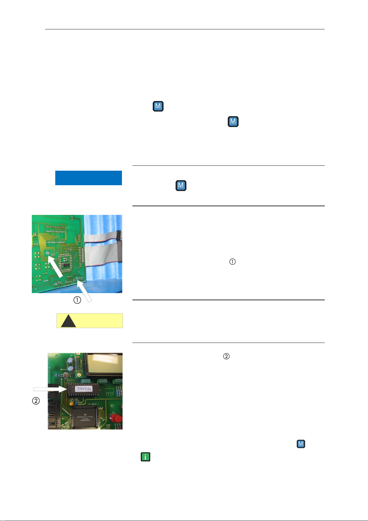
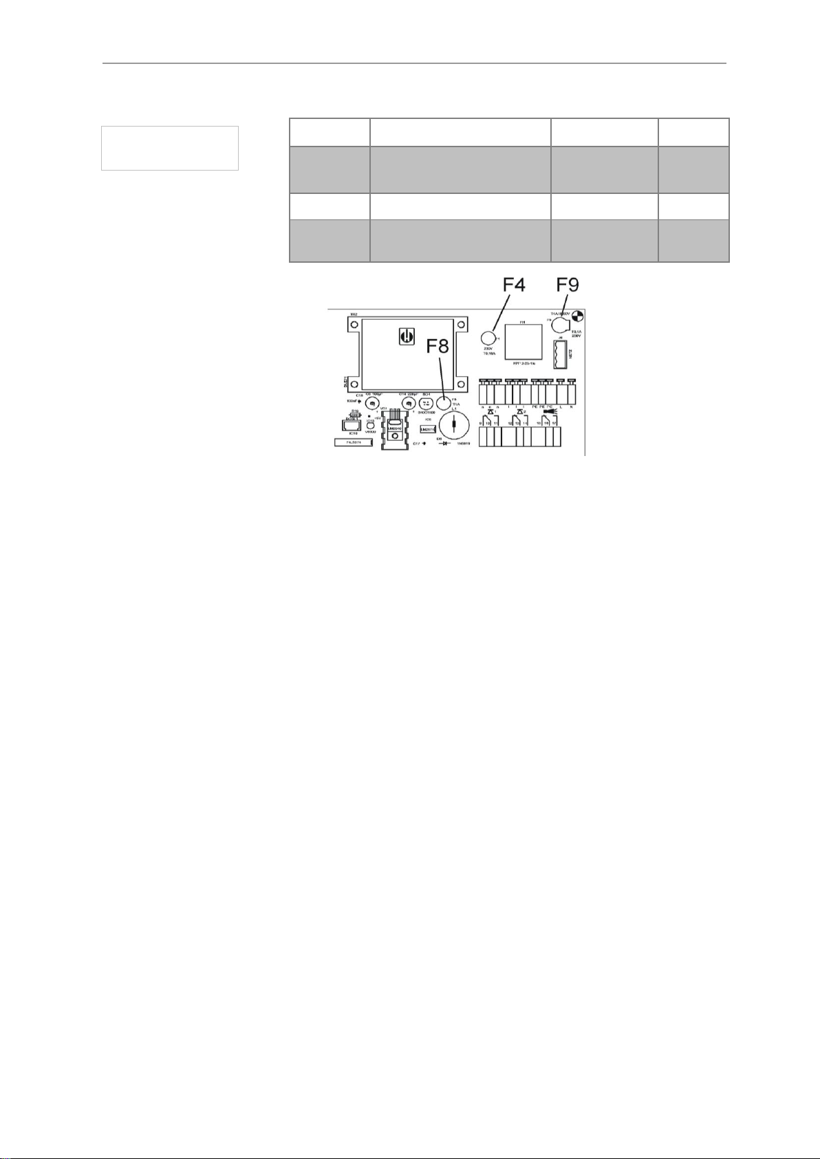
Replacing the EPROM (software update)
(Required tool: Torx 8x60)
Switch off the instrument.
Loosen the six fastening screws of the display circuit board
Avoid static charges during installation/de-installation and ob-
serve the direction of installation!
Non-adherence can result in damage to or destruction of the elec-
tronic components on the circuit board or of the EPROM.
Carefully remove the EPROM from the socket (please make a
note of the direction of the marking).
Insert the new EPROM.
Fasten the display circuit board.
Switch on the instrument.
Opening the factory programming
After replacing the EPROM, carry out basic programming.
Switch on the instrument by simultaneously pressing the and
keys. Your programmed settings are lost and the factory set-
tings are reset (also see the operating instructions!).
CAUTION
!
NOTE

Carrying out maintenance
11
Installing the interface cards SK910, UK910,
RS910 (only Testomat 2000®)
Switch off the instrument:
Open the upper housing cover:
Insert the plug-in circuit board into the left-hand slot with the com-
ponent side on the left (contact no.1 is at the top).
Switch on Testomat 2000®.
Under menu item
select either or for
the cards SK910/UK910.
Select for the interface card RS910.
Voltage interface UK 910 Interface RS910 (RS232)
Avoid static charges during installation!
Non-adherence can result in damage to or destruction of electronic
components on the circuit board.
Interface SK910
CAUTION
!

Carrying out maintenance
12
Position and function of the fuses
Description
Error during failure
Rate
Art. No.
F1
Instrument not functioning
T0,2A (115V)
31594
F2
Instrument not functioning
T0,1A (230V
T1A (24V)
31595
31592
F4
"Ff. 24V failure" dosing
pump not functioning
T0,16A (230V)
T0,315A(115V)
31622
31585
F5
Display failure
T0,315A
31585
F6
"Low water level", alarm
relay active
T0,315A
31585
F7
Power output not function-
ing
T0,08A
31596
F8
"Ff. 24V failure" dosing
pump not functioning
T1A
31592
F9
Instrument not functioning
GS-M 5x20V
4A
31582
F8 F1 F2 F4 F9
F7 F5 F6
Fuses
Testomat 2000®
Carrying out maintenance
13
Description
Error during failure
Rate
Art. No.
F4
Instrument not functioning
T0,16A (230V)
T0,315A(115V)
31622
31585
F8
Instrument not functioning
T1A
31592
F9
Instrument not functioning
GS-M 5x20V
4A
31582
In case of overload or short circuiting at the relay outputs, fuse F9 is
triggered (if the power for the external consumers is supplied from
terminals "l" of "n").
Fuses
Testomat ECO®

Carrying out maintenance
14
Repairing or replacing the dosing pump
Maintenance rate
The dosing pump DOSIClip®is a high-precision piston dosing pump,
which makes up to 400 000 pump strokes per year depending on the
settings (a measurement all 10 minutes x 4 pump strokes every day).
To ensure proper operation for many years, we recommend sending
in the pump for servicing every 2-3 years.
Calibration on-site not possible!
We would like to point out that a repair of the dosing pump should be
performed only marginally, because calibration of the dosing pump
on-site is not possible.
We recommend exchanging a defective pump and sending it in for
servicing to the factory.
A pump which does not function properly results in incorrectly meas-
ured values (e.g. error message "Mf. Analysis"). If you have problems
with the dosing pump, we recommend replacing it.
Proceed as follows to replace it:
1. Switch off the instrument.
2. Loosen the five cables of the terminal connections using a
suitable screwdriver.
3. Loosen the hose connections at the indicator bottle and at
the measuring chamber holder.
4. Collect the indicator in a container!
5. Use a screwdriver to push the lock of the pump housing
downwards and remove the housing from the top
6. At first, place the replacement pump on top of the DIN rail
and push the housing downwards until the lock engages
7. Reconnect the cables (observe the colour sequence!)
8. Reconnect the hose connections (note the suction and pres-
sure side!)
CAUTION
!
NOTE

Special function “Adjust mode”
15
Checking dosing
When measuring the hardness, it is checked whether the yellow val-
ue is at least 50 below the limit value after each (except the first)
dosing stroke. Each stroke usually results in the value being reduced
by 80 to 100 digits.
Manually activate the dosing pump once.
In “Adjust mode”, display the yellow value under “G:####”.
It is essential that the stirrer is switched on during the checking pro-
cedure.
Checks can only be carried out with indicator type TH!
Special function “Adjust mode”
The adjust mode is used for adjusting the overflow detection and
testing the optical amplification setting.
The amplification setting is carried out in the normal measuring mode
of the instrument, i.e. manual adjustment is not required. The test
described below is only used for checking and error detection.
Call of adjust mode
Press and hold the "DOWN" (1) key and switch on the instrument.
Back to measuring mode
Press the "DOWN" (1) and "LEFT" (9) keys simultaneously.
NOTE
NOTE

Special function “Adjust mode”
16
Testing of the overflow detection
Press the “M” (3) key to open the input valve IN.
Only Testomat2000®:the “IN” LED (6) illuminates.
The “ANALYSIS” (7) LED must illuminate when the water flows
through the overflow borehole of the measuring chamber (If this is
not the case, adjust the overflow detection as described above).
Press the “i” (4) key to open the output valve OUT.
Only Testomat2000®:the “OUT” LED (8) illuminates.
Checking the automatic adjustment
Prior to adjustment, fill the measuring chamber with water until
overflow occurs.
Switch to “Adjust mode” (see “Calling adjust mode”).
Press the “ENTER” (2) key to switch on the transmit diodes and
the stirring mechanism.
Press the "UP" (5) key to start automatic adjustment.
Press the “Manual” button on the dosing pump.
Read the values for yellow (Y:) and red (R:). Both values have to
be 900 +/- 20.
If these values are not achieved, it may be due to the following rea-
sons:
The water is turbid.
Air bubbles in the water.
The measuring chamber is not filled correctly.
The sight-glass windows are soiled or cracked.
The receiver optics (lenses) is soiled.
The plug connector of the flexible cable is not locked (loose con-
tact).
The measuring chamber holder is leaky, entered water has de-
stroyed the electronics on the circuit board.
Electronic component on the plug-in circuit board T2000-SE (Art.
no. 40091) is defective.

Water consumption
17
Water consumption
Water consumption of the instruments is composed of the analysis-
relevant volume (18.1 ml per analysis), of the measuring water ad-
justment (150 –200 ml per analysis), the water consumption for the
internal flushing time 0.5 l (500 ml /minute). and the water consump-
tion for flushing after analysis (approx. 50 ml).
Flushing is carried out by simultaneously opening the inlet and
outlet valve.
The values for measuring water adjustment and internal flush-
ing are variable and depend on the input water pressure.
Water consumption for internal flushing with a programmed flush-
ing time of 10 seconds is 83 ml. Shorter or longer flushing times in-
fluence the required volume of water in a linear fashion.
Default setting:
Measuring water inlet pressure 2 bar = approx. 200 ml measuring
water adjustment + 18.1 ml analysis volume = 218.1 ml / per analysis
Example: 10 sec. internal flushing time + analysis = total waste water
quantity / per analysis
83 ml + 218.1 ml = 301.1 ml / per analysis
For connections longer than 3 m and with an internal hose diameter
of 6 mm a minimum internal flushing time of 10 seconds is required
to ensure that a valid sample is taken from the sampling line.
Indicator consumption
Testomat functions via automatic titration. During the analysis pro-
cess, the indicator is titrated drop-by-drop into the measuring cham-
ber by the dosing pump until the colour changes. Please note that the
applied indicators each provide a specific resolution.
The greater the hardness of the water being analysed, the higher
the indicator consumption!
Moreover, indicator consumption is influenced by the frequency of
analysis.
Example: Three strokes are dosed into the measuring chamber by
the dosing pump at a hardness of 0.1 °dH. In this case, a 500 ml
bottle of indicator is sufficient for 16 667 strokes. In other words, 5
555 analyses are possible. If an analysis is carried out every 30
minutes, for instance, the indicator bottle will last for approx. 2 777
hours. Resulting in an annual consumption of 3.15 bottles. Please
remember that this calculation is an approximate value for indicator
type TH 2005.
NOTE

Indicator consumption
18
Indicator TH2025, TH2100, TH2250
Number of analysis and range with 500 ml
Range in hours
Water hardness (°dH)
Num. of
Analysis
Interval (as a result of idle time and flush times/AUX) minutes
TH2025
TH2100
TH2250
0
2
5
10
30
60
90
200
0,25
1,0
2,5
8333
278
556
972
1667
4444
8611
12778
28056
0,50
2,0
5,0
5556
185
370
648
1111
2963
5741
8519
18704
1,00
4,0
10,0
3333
111
222
389
667
1778
3444
5111
11222
1,50
6,0
15,0
2381
79
159
278
476
1270
2460
3651
8016
2,00
8,0
20,0
1852
62
123
216
370
988
1914
2840
6235
2,50
10,0
25,0
1515
51
101
177
303
808
1566
2323
5101
Annual requirement indicator 500 ml (365d x 24h) 8760 hours/year
Water hardness (°dH)
Num. of
Analysis
Interval (as a result of idle time and flush times/AUX) minutes
TH2025
TH2100
TH2250
0
2
5
10
30
60
90
200
0,25
1,0
2,5
8333
32
16
9
5
2
1,0
0,7
0,3
0,50
2,0
5,0
5556
47
24
14
8
3
1,5
1,0
0,5
1,00
4,0
10,0
3333
79
39
23
13
5
2,5
1,7
0,8
1,50
6,0
15,0
2381
110
55
32
18
7
3,6
2,4
1,1
2,00
8,0
20,0
1852
142
71
41
24
9
4,6
3,1
1,4
2,50
10,0
25,0
1515
173
87
50
29
11
5,6
3,8
1,7
Indicator TH2005
Number of analysis and range with 500 ml
Range in hours
Water hard-
ness (°dH)
Num. of
Analysis
Interval (as a result of idle time and flush times/AUX) minutes
0
2
5
10
30
60
90
200
0,05
8333
278
556
972
1667
4444
8611
12778
28056
0,10
4167
139
278
486
833
2222
4306
6389
14028
0,20
2381
79
159
278
476
1270
2460
3651
8016
0,30
1667
56
111
194
333
889
1722
2556
5611
0,40
1282
43
85
150
256
684
1325
1966
4316
0,50
1111
37
74
130
222
593
1148
1704
3741
Annual requirement indicator 500 ml (365d x 24h) 8760 hours/year
Water hard-
ness (°dH)
Num. of
Analysis
Interval (as a result of idle time and flush times/AUX) minutes
0
2
5
10
30
60
90
200
0,05
8333
32
16
9
5
2
1,0
0,7
0,3
0,10
4167
63
32
18
11
4
2,0
1,4
0,6
0,20
2381
110
55
32
18
7
3,6
2,4
1,1
0,30
1667
158
79
45
26
10
5,1
3,4
1,6
0,40
1282
205
102
59
34
13
6,6
4,5
2,0
0,50
1111
237
118
68
39
15
7,6
5,1
2,3
(All information without guarantee)

Manual measured value check
19
Manual measured value check
The measured value check of the Testomat instruments is usually
carried out during a laboratory analysis of the measuring water. In
special cases, this check can also be carried out via direct input of a
standard solution, created especially for this task, into the measuring
chamber.
Creating a standard solution
The standard solution must be created on-site for rapid application.
For example, take a 1000 ppm solution and dilute it until you
achieve the desired value in the upper third of the measuring
range.
Manual supply of the standard solution
Please stop the water supply to the instrument.
Please remove the right-hand plug from the measuring chamber.
The measuring chamber is manually filled with the standard solu-
tion via this borehole after starting the measurement. Common la-
boratory spray bottles can be used for this task.
To start the check, activate the measurement via the key.
Testomat 2000® starts with an analysis cycle. If you have pro-
grammed a flushing time, do not fill the measuring chamber until
the output valve has closed (“OUT” LED extinguishes).
Fill the measuring chamber with the standard solution until it over-
flows. The input valve closes (“IN” LED extinguishes). This solution
is then drained (flushing the measuring chamber).
Once the output valve has closed ("OUT” LED extinguishes), refill
the measuring chamber with the standard solution until it over-
flows. The filling level falls to the intended sample volume.
The measured value is displayed once the analysis has finished.
Valve
block
NOTE

Troubleshooting
20
Troubleshooting
Error message MST analysis
A measuring fault analysis occurs when the water in the measuring
chamber is too “light” after the second dosing.
Check the following points if MST analysis is displayed:
1. The indicator’s expiry date has been exceeded.
Remedy:
There is insufficient dye in the indicator. Use a new indicator.
When using an indicator that is not from Gebr. Heyl, replace it with
the one recommended by us.
2. The stirring bar in the measuring chamber holder fails to
rotate, resulting in an insufficiently mixed indicator.
Remedy:
The stirring bar is stuck due to soiling in the stirring area of the
measuring chamber holder. Clean the measuring chamber.
The measuring chamber holder is leaky, entered water has de-
stroyed the electronics on the circuit board. Change the measuring
chamber holder.
The plug connector of the flexible cable is not locked (loose con-
tact). Insert the plug properly into the socket.
The magnet in the stirring bar is too weak. Change the stirring bar.
If necessary, insert a stirring bar.
Check the plug contact of the flexible printed circuit board. If nec-
essary, replace the measuring chamber holder.
3. The pump doses insufficient indicator.
Remedy:
Check the dosing pump (see “Checking the dosing pump”). Contact
your customer service representative or if necessary, replace the dos-
ing pump.
Check pump dosing (see “Checking dosing”). Contact your custom-
er servicerepresentative or if necessary, replace the dosing pump.
4. Air is trapped in the indicator hose.
Remedy:
Bleed the dosing hoses by pressing the “Manual” button on the
dosing pump several times.
Make sure that all the indicator hoses are fitted correctly. If not, air
may enter the hoses!
If the error re-occurs, replace the bottle insert for a screw cap with
a suction tube (art. no.: 40135).
Make sure that the suction and pressure hose set is not kinked or
trapped. If necessary, replace the hoses. Complete suction hose
(art. no. 40011), complete pressure hose (art. no. 40016).
This manual suits for next models
1
Table of contents
Other Neomeris Test Equipment manuals


