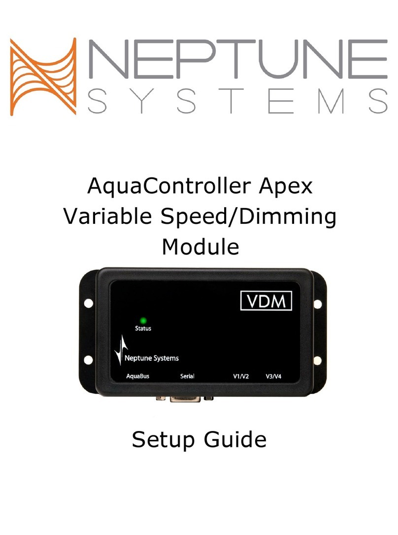
Neptune Systems AquaController II User manual

AquaControllerIIOwner's
Manual
Version 1.60
?Neptune Systems
6288 San Ignacio Ave. #B
San Jose, CA 95119
Phone (408) 578-3022 • Fax (408) 578-9383
AquaController II Owner’s Manual V1.60
Copyright 1999 -Neptune Systems
All rights reserved

AquaController II Owner’s Manual V1.60
Copyright 1999 -Neptune Systems
All rights reserved
Table of Contents
1. INTRODUCTION........................................................................................7
SCOPE OF THIS DOCUMENT ...............................................................................7
FEATURE LIST...................................................................................................7
2. GETTING STARTED.................................................................................9
BASE UNIT INSTALLATION................................................................................9
CONTROL INTERFACE INSTALLATION..............................................................10
SERIAL PORT INSTALLATION...........................................................................10
Macintosh Installation..........................................................................................10
PC Compatible Installation..................................................................................11
3. MENU OVERVIEW..................................................................................13
RUN DISPLAY .................................................................................................15
CONTROL AND STATUS ...................................................................................16
Feed Cycle...........................................................................................................16
Manual Control....................................................................................................17
Power Fail Log ....................................................................................................17
Power Log...................................................................................................................17
Reset Power Log..........................................................................................................18
DATA LOGGING ..............................................................................................18
Print Data Log.....................................................................................................18
Display Data Log.................................................................................................18
Reset Data Log.....................................................................................................18
Log Interval .........................................................................................................19
SETUP.............................................................................................................19
Timer Setup..........................................................................................................19
Clock Setup..........................................................................................................19
Setting the Tank Time or Clock Time...........................................................................19
Enabling/Disabling Advanced Clocking ........................................................................19
Leap Seconds...............................................................................................................20
Temperature Setup...............................................................................................20
pH Setup..............................................................................................................20
ORP Setup............................................................................................................20
Login Setup..........................................................................................................20
Login: On or Off..........................................................................................................21
Login Name.................................................................................................................21
Login Password ...........................................................................................................21
Pager Setup..........................................................................................................21
Pager Enable................................................................................................................21
Pager Number..............................................................................................................21
Alarm Name.................................................................................................................22
Dial Delay....................................................................................................................22
Re-page Delay..............................................................................................................22
Pager Test....................................................................................................................22
AquaController II Owner’s Manual V1.60
Copyright 1999 -Neptune Systems
All rights reserved
Init Memory
................................
................................
................................
.........
22
SELF TEST ......................................................................................................22
4. PROBE INSTALLATION AND CALIBRATION..................................25
PROBE INSTALLATION.....................................................................................25
Temperature Probe Installation...........................................................................25
pH Probe Installation...........................................................................................25
ORP Probe Installation........................................................................................26
PROBE CALIBRATION ......................................................................................27
Temperature Calibration .....................................................................................27
pH Calibration.....................................................................................................27
ORP Calibration..................................................................................................28
5. PROGRAMMING THE AQUACONTROLLER II................................31
PROGRAMMING BASICS...................................................................................31
Timer Names........................................................................................................31
Timer Program ....................................................................................................32
Repeat Interval ....................................................................................................32
Feed Interval........................................................................................................33
TEMPERATURE CONTROLLER SETUP ...............................................................33
Temperature Control Program.............................................................................34
Fixed Temperature.......................................................................................................34
Seasonal Temperature Variation...................................................................................35
PH CONTROLLER SETUP .................................................................................36
pH Control Program............................................................................................37
ORP CONTROLLER SETUP ..............................................................................38
ORP Control Program.........................................................................................38
TIMED EVENTS SETUP.....................................................................................39
Timed Lighting.....................................................................................................39
Timed Pumps.......................................................................................................40
Repetitive and Random Events.............................................................................41
Seasonal Lighting Variation.................................................................................42
Simulating the Moon Cycle..................................................................................43
Feed Cycle Timer Events .....................................................................................44
Externally Switched Events ..................................................................................45
Alarms.................................................................................................................46
Hysteresis ............................................................................................................47
ADVANCED PROGRAMMING ............................................................................49
Statement Evaluation Order.................................................................................49
6. SERIAL PORT INTERFACE................................................................51
SERIAL CONNECTOR PINOUT...........................................................................51
SERIAL PORT COMMANDS...............................................................................52
APPENDIX A -TROUBLE SHOOTING....................................................55
APPENDIX B -SAMPLE PROGRAMS......................................................57

AquaController II Owner’s Manual V1.60
Copyright 1999 -Neptune Systems
All rights reserved
D
EFAUL
T
T
IMER
N
AMES
................................
................................
.................
57
DEFAULT PROGRAM........................................................................................57
AquaController II Owner’s Manual V1.60
Copyright 1999 -Neptune Systems
All rights reserved

AquaController II Owner’s Manual V1.00b
Copyright 1998/1999 -Neptune Systems
All rights reserved
7
1. Introduction
Scope of this Document
Congratulations, you have just purchased the most advanced aquarium
controller on the market! It is recommended that you completely read the
Owner's Manual before proceeding to set up the AquaController II to
perform any task.
Feature List
The following features are fully supported in the AquaController II base
unit.
??Lighting Control
??Wave Maker
??Simulated Moon Cycle
??Seasonal Lighting Variation
??Seasonal Temperature Variation
??1 External Switch Input
??Temperature Monitor and Control
??pH Monitor and Control
??ORP Monitor and Control
??Flash Memory for Easy Firmware Upgrades
??Data Logging
??RS232 Computer Interface
Chapter
1
AquaController II Owner’s Manual V1.00b
Copyright 1998/1999 -Neptune Systems
All rights reserved
8
?
?
Direct Connection to External Modem
??Local and Remote Alarms
??Simple Yet Sophisticated Programming Language
??Built in Self Test

AquaController II Owner’s Manual V1.00b
Copyright 1998/1999 -Neptune Systems
All rights reserved
9
2. Getting Started
Base Unit Installation
The following figure points out all the connectors located on the side of
the AquaController II. Please refer to it during installation.
Power
9V DC X10
RJ11 Serial
Mdin 8 Temp ORP
BNC pH
BNC
Figure 1: AquaController II Connectors
The AquaController II should be installed in a dry environment that has
little chance of getting wet. The AquaController II is a sensitive piece of
electronic equipment and is not waterproof. Ideally, it should be located
several feet from the aquarium. Velcro strips with adhesive backing can be
used to install the controller in its permanent location. Velcro strips work
well because the unit can be easily removed from its mounting point to
replace the 9V battery.
To prevent the loss of data logging and clock information, it is highly
recommended that a new 9V battery is installed. In the event of a power
outage the battery will maintain the internal state of the unit and allow for
the resumption of control of the aquarium as soon as power returns. A
high quality alkaline battery will keep the internal processor operational for
approximately 4 hours when an AC power failure occurs. When the
battery is low and should be replaced a ‘battery low’ display will flash on
the AquaController II’s Display. It should be noted that no state changes
will occur in the external control modules during a power outage. After
Chapter
2
AquaController II Owner’s Manual V1.00b
Copyright 1998/1999 -Neptune Systems
All rights reserved
10
power is
returned, all controlled devices will be in the correct state within
the Repeat Interval. The default interval is 5 minutes. See section ‘Repeat
Interval’ on page 32 for more details on modifying the Repeat Interval.
The 9V-DC power adapter should be plugged into a 120V wall socket and
the plug on the end of the cable should be connected to the power
connector on the AquaController II. Refer to the above figure for the
location of the connector.
Powerheads and pumps switching on and off generate power spikes that
can damage electronic equipment. The AquaController II has protection
circuitry in the base unit; however, it is recommended as an added safety
precaution to plug the controller in a 'clean' AC socket. Power strips with
transient suppression circuitry can be used to make a 'clean' socket and to
prevent power surges from damaging the AquaController II. Coil up all
power cords to reduce the amount of radiated electrical noise.
Control Interface Installation
Simply plug the control interface into the wall outlet located close to the
AquaController II and aquarium. It may be necessary to use one or more
power strips if multiple devices are to be controlled. Plug one end of the
cable with the RJ11 connectors (phone cable) into the Control Interface
and the other end into the AquaController II.
Serial Port Installation
Macintosh Installation
To connect the AquaController II to a Macintosh computer simply use an
Apple NULL modem (printer) cable. The cable necessary is exactly the
same as is used to connect two Apple Macintosh's together over an
AppleTalk network. Simply place one of the mini-DIN 8 connectors into
the AquaController II serial port (see figure 1) and the other end into the
modem or printer port of the Macintosh.
Any of the many serial port communications programs for the Macintosh
can be used. Kermit is one such public domain program. The
communications program on the Macintosh must be configured to run at
9600 baud, 8 bits/char, no parity, 1 stop bit and no flow control. Also
make sure that the correct serial port (printer or modem) on the Macintosh

AquaController II Owner’s Manual V1.00b
Copyright 1998/1999 -Neptune Systems
All rights reserved
11
is selected.
To test the port type several carriage returns and an AquaController>
prompt should be returned. At this point data can be downloaded from
the AquaController II to the host Macintosh. Please refer to section ‘Serial
Port Commands’ on page 52 for a detailed description of the serial port
commands.
PC Compatible Installation
To connect the AquaController II to an IBM/PC compatible computer
use our serial cable (P/N SERPC). To install simply place the mini-DIN 8
connector into the AquaController II serial port (see figure 1) and the
DB25 connector into the PC's serial port. For PCs with DB9 connector a
DB25 to DB9 converter is required in addition to the serial cable.
Any of the many serial port communications programs for the PC can be
used. The terminal emulator in Windows (Hyperterminal) or a public
domain program such as Kermit will both work. The communications
program on the PC must be configured to run at 9600 baud, 8 bits/char,
no parity, 1 stop bit and no flow control. Also make sure that the correct
serial port is selected (COM1 or COM2).
To test the port type several carriage returns and an AquaController>
prompt should be returned. At this point data can be downloaded from
the AquaController II to the host PC. Please refer to section ‘Serial Port
Commands’ on page 52 for a detailed description of the serial port
commands.
AquaController II Owner’s Manual V1.00b
Copyright 1998/1999 -Neptune Systems
All rights reserved
12
This page intentionally left blank.

3. Menu Overview
The options and menus in the controller may seem overwhelming at first,
but after a little practice you will find that they are arranged in a logical and
consistent manner.
All menus and sub-menus follow the same user interface. The Up and
Down buttons move the arrow cursor up and down. When the cursor
reaches the bottom entry and the down button is pressed again, the menu
items scroll as expected. Similarly, if the cursor is at the top and the up
button is pressed, the menu items scroll. The Select button activates the
current menu entry pointed to by the cursor. The activation will execute a
command, bring up another menu, or exit the current menu.
The menu choices are in a circularly linked list, so repeated presses of the
Up (or Down) button will cycle through all the choices. Common to all
menus is the Exit entry. When Exit is selected, the current sub-menu pops
up and control is returned to the previous (next higher) level menu.
To make it easier to enter data into the AquaController II, all three of the
buttons have an auto repeat function. When any button is pressed for
greater than 3/4 of a second, the current action begins to repeat. If the
button is pressed an additional 1 second, the auto repeat rate increases.
For quick reference the following table lists all of the menus and
commands available to the AquaController II. On the left side of the table
are the root menu entries. Entries in the 2nd through 4th columns are sub-
menus of the column to the left of it.
Chapter
3
AquaController II Owner’s Manual V1.00b
Copyright 1998/1999 -Neptune Systems
All rights reserved
14
Root Level 2nd Level 3rd Level 4th Level
Run
Feed
Manual Cntl
Power Log
Control & Status Power Fail Log Reset Power Log
Exit
Display Lock
Exit
Print Data Log
Display Log (T, pH, ORP)
Data Log Display Log (Oxy, Cond)
Reset Data Log
Log Interval
Exit
Modify Name
Timer Names Add Name
Delete Name
Exit
Modify State
Timer Setup Timer Program Add State
Delete State
Exit
Repeat Interval
Feed Interval
Exit
Tank Time Set
Clock Time Set
Clock Setup Type: Adv/Normal
Setup Leap Second
Exit
pH Calibration
pH: On/Off
pH Setup pH Temp Comp:
Exit
Temp Calibration
Temp: On/Off
Temp Setup Temp Celsius
Temp Fahrenheit
Exit
ORP Calibrate
ORP Setup ORP: On/Off
ORP pH Comp:
Exit

AquaController II Owner’s Manual V1.00b
Copyright 1998/1999 -Neptune Systems
All rights reserved
15
Root Level 2nd Level 3rd Level 4th Level
Login: On/Off
Login Setup Login Name
Login Password
Pager: On/Off
Pager Number
Pager Setup Dial Delay
Repage Delay
Alarm Name:
Serial Setup Type: RS232/RS485
Exit
Init Memory
Exit
Run Display
The Run Display indicates the date, system time, temperature (temp), pH,
and ORP. During most of the AquaController II operation this will be the
active display. If no input occurs (button selection) the LCD screen will
automatically return to this display. It can be selected by pressing the Select
(left) button when the arrow cursor is pointing at RUN.
Jan 10 8:10:30
Figure 2: Clock Display
In Figure 2 Normal Clocking is enabled and the first line displays the date
(month day) followed by the tank time (hour:minute:second). The clock
Time can also displayed by setting Advanced Clocking to ON (see section
‘Enabling/Disabling Advanced Clocking’ on page 19).
The second line indicates the current status of the control modules; the
first character represents the status of the first timer name, the second
character represents the status of the second timer name and so on. If the
character displayed is either an "M" or "m" then that timer is in manual
mode (operation). The "M" indicates that the controlled device is
operating and the "m" indicates the device is idle. Manual Mode Operation
is described in section ‘Control and Status’ on page 16
The other special characters displayed on this line indicate that the timer is
in Automatic mode, and the controlled device(s) are either "on" or "off".
AquaController II Owner’s Manual V1.00b
Copyright 1998/1999 -Neptune Systems
All rights reserved
16
The character that is displayed for a particular timer is programmed in the
'Setup:Timer Setup:Timer Names' sub-menu. The following table shows
the special characters (the first column represents on and the second off):
Typically Lights
Typically Heater/Chiller
Typically Pumps/Powerheads
Other Controlled Devices
Figure 3: Run Display Special Characters
In the figure below the monitored probes are displayed. with temperature
(°F or °C), pH, and ORP (millivolts) enabled. The UP button is used to
toggle between the Clock Display and the Monitored Probes display.
Temp pH ORP
78.3 8.34 382mV
Figure 4: Monitored Probes Display
.
Pressing the Down button while the Run Display is active will initiate a
Feed Cycle. During the Feed Cycle the display will show a countdown of
the number of seconds remaining. The Run Display is resumed following
the completion of the Feed Cycle. The Select button can be used to end
the Feed Cycle early. See section ‘Feed Cycle’ on page 16 for more details.
To exit the Run Display and enter the root level menu press the Select
button.
Control and Status
The control and status menu option allows the user to take any timer out
of the automatic mode of operation and force it to either an "on" or "off"
state as well as viewing other operational status.
Feed Cycle
A special case of manual mode of operation is the Feed Cycle. This option

AquaController II Owner’s Manual V1.00b
Copyright 1998/1999 -Neptune Systems
All rights reserved
17
allows the user to shut down certain pumps, powerheads, etc. for a fixed
period of time for the purpose of feeding the tank. To start a Feed Cycle
select the Feed Cycle entry in the Control and Status menu. When this
mode is entered, the Feed Cycle controlled modules are temporarily forced
into the programmed state. The display shows a countdown of the
number of seconds remaining. When the count reaches zero, the Feed
Cycle controlled modules return to normal operation. The Feed Cycle can
be interrupted early by pressing the Select button. See section ‘Feed Cycle
Timer Events’ on page 44 for instructions on how to program a timer to
use a Feed Cycle and section ‘Feed Interval’ on page 33 on how to change
the Feed Cycle duration.
To reduce the number of button presses required to initiate a Feed Cycle,
a shortcut has been added to the Run Display command. When the Run
Display is active (see section ‘Run Display’ on page 15), the Down button
can be used to initiate a Feed Cycle.
Manual Control
The manual timer menu allows you to place a control module out of
Automatic Mode and turn it continuously "on" or continuously "off". The
following procedure is used to modify the on, off or automatic status of a
timer:
1. Go to the Control & Status:Manual Control menu.
2. Use the Up and Down buttons to locate the desired timer. When
the cursor points to the desired timer press the Select button.
3. The underline cursor should now be under the ON, OFF, or
AUTO status of the timer. Use the Up and Down buttons to
scroll to the desired state. Press the Select button to complete the
operation.
Power Fail Log
The power fail menu allows you to display the last power failure and reset
the power failure log.
Power Log
Selecting the power log menu display the last power failure time/date and
the power restored time/date of the last power interruption. If ‘none’ is in
the power failed entry then no power failure has occurred.
AquaController II Owner’s Manual V1.00b
Copyright 1998/1999 -Neptune Systems
All rights reserved
18
Reset Power Log
Activating this menu entry will reset the power failure and power restored
time/date entries to ‘None’.
Data Logging
Data logging is a powerful feature that enables accurate tracking and
recording of the conditions in the aquarium. There are many possible uses
for the data, some of which include analysis to help find cause and effect
relationships, trends which may foreshadow potential problems, and
monitor the tank conditions necessary to induce fish or coral spawning.
The AquaController IIs internal memory can hold up to 744 data logs.
This size log buffer is enough to hold hourly data logs for four weeks.
When the data log exceeds 744 entries, the oldest log entry is replaced by
the newest log entry.
Print Data Log
The Print Data Log menu dumps the entire data log to the serial port. It
may take several seconds to dump the Data Log to the serial port, so be
patient. This operation cannot be interrupted. A terminal program on a PC
can capture the dumped data, and allows you to store it to disk. The data
can then be input into a spreadsheet, or similar program to generate graphs
or find trends. Refer to section ‘Serial Port Installation’ on page 10 for
instructions on how to attach the serial port to a computer. The 'd'
command input from the serial port performs the same function.
Display Data Log
The Display Data Log menu allows you to scroll through the contents of
the data log on the LCD screen. The first line displays the Month/Day
Hour:Minute of the datalog entry and the second line displays the
Temperature, pH, and ORP.
The initial display shows the earliest data entry and the Down button
scrolls to a later data entry. The Up button scrolls the display to an earlier
data entry. To exit the Display Data Log menu press the Select button.
Reset Data Log
The Reset Data Log menu option clears the log memory in the
AquaController II. NOTE: The data log is also cleared if the tank time is
changed or the log interval is modified. The 'r' reset command from the

AquaController II Owner’s Manual V1.00b
Copyright 1998/1999 -Neptune Systems
All rights reserved
19
serial port performs the same function.
Log Interval
The Log Interval menu allows you to set how often the AquaController II
logs a pH, ORP, or temperature measurement to the data log. To modify
the interval select Log Interval and use the Up and Down buttons to
advance to the desired setting. When the correct interval is displayed press
the Select button. Sixty minutes is the default setting for log interval.
NOTE: The data log is also cleared if the tank time is changed or the log
interval is modified.
Setup
Timer Setup
The timer setup and programming instructions are described in chapter 5
on page 31
Clock Setup
Setting the Tank Time or Clock Time.
The AquaController II has the capability to maintain two separate times on
two separate clocks. The tank clock keeps track of the time in the tank and
is the clock used by the timer program to turn off or on the desired
modules. The time clock is only included as a convenience to the user. It
can be set to display the actual time in case it is different than the time
used to control and monitor the tank. Following the directions listed below
can set either clock:
1. Go to the Setup:Clock Setup:
2. Select either Set Tank Time or Set Clock Time from the menu
depending on which clock needs to be set.
3. Use the Up and Down buttons to adjust the selected field to the
desired value. When the value is correct use the Select button to
advance to the next field. Repeat until all time values are entered.
Enabling/Disabling Advanced Clocking
Since some of the lighting control statements (SUN and MOON) occur at
fixed times, you may want to have the Tank Time and Clock Time set to
different times; Advanced clocking allows for this possibility. The
Advanced Clocking feature enables both the Tank Time and the Clock
AquaController II Owner’s Manual V1.00b
Copyright 1998/1999 -Neptune Systems
All rights reserved
20
Time to be visible in the Run Display simultan
eously. If Advanced
Clocking is disabled only the tank time is displayed in the Run Display.
The Tank Clock is always used in the timer program evaluation regardless
of the setting of Advanced Clocking. To enable or display Advanced
Clocking do the following:
1. Go to the Setup:Clock Setup:
2. Use the Up and Down buttons to move the cursor to either Adv
Clocking. When the cursor is positioned by the correct action
press the Select button; the clock mode will toggle.
3. To exit the clock setup menu, use the Up and Down buttons to
scroll through the options to the 'Exit' entry. Press the Select
button to exit the clock setup menu.
Leap Seconds
The Leap Seconds allows the user to fine tune the accuracy of the clocks
used in the AquaController II. The number programmed into the
AquaController II indicates how many seconds to adjust the internal clock
per day. For example if the clock is gaining 1.5 seconds per day, a value of
-1.5 would be entered to offset this inaccuracy. The AquaController II uses
this value to slow its time down by 1.5 seconds each day. To modify this
entry select Leap Seconds and use the Up and Down buttons to scroll to
the desired Leap Seconds value. When the correct value is displayed press
the Select button.
Temperature Setup
Temperature setup and probe installation are described in section
‘Temperature Probe Installation’ on page 25 and ‘Temperature Calibration’
on page 27.
pH Setup
pH setup and probe installation are described in section ‘pH Probe
Installation’ on page 25 and ‘pH Calibration’ on page 27.
ORP Setup
ORP setup and probe installation are described in section ‘ORP Probe
Installation’ on page 26 and ‘ORP Calibration’ on page 28.
Login Setup

AquaController II Owner’s Manual V1.00b
Copyright 1998/1999 -Neptune Systems
All rights reserved
21
This ROM version supports a modem so that a telephone connection is
possible without having a PC at the remote AquaController II site. For this
feature to work the AquaController II needs to be connected to the
modem with the modem serial cable. Our technical support department
supports only modems sold by Neptune Systems. Other Hayes command
set modem may work with the AquaController II, however, we make no
guarantees.
The following configuration must be set correctly for Login to function.
The login setup menu is found in Setup->Login Setup.
Login: On or Off
This menu turns login on or off. If On password login is enabled. Login
should be enabled only if the AquaController II is connected directly to a
modem, otherwise it should be left off.
Login Name
This menu allows for the setting of login name. The up and down keys
scroll through the letters of the alphabet and the select key moves to the
next letter. The space character is used to signal the end of the login name
if less than 8 characters are entered. This field is limited to 8 characters.
Login Password
Thismenu allows for the setting of login password. The up and down keys
scroll through the letters of the alphabet and the select key moves to the
next letter. The space character is used to signal the end of the login name
if less than 8 characters are entered. This field is limited to 8 characters.
Pager Setup
The following configuration must be set correctly for Alarm paging to
function. The pager setup menu is found in Setup->Pager Setup.
Pager Enable
This menu turns paging on or off. If On paging is enabled.
Pager Number
This field is self-explanatory; this number is called if an alarm condition is
on. The space character is used to signal the end of the pager number if
less than 16 numbers/characters are entered. Some special characters other
than numbers may be entered into the phone number. The following table
lists and describes these characters:
AquaController II Owner’s Manual V1.00b
Copyright 1998/1999 -Neptune Systems
All rights reserved
22
Character
Meaning
WWait unit dial tone
before dialing
,Pause 2 seconds
*Send the ‘*’ tone
#Send the ‘#’ tone
+
Alarm Name
This field is used by the AquaController II to determine which timer name
to monitor for an alarm condition. The default name is ALM. Repeatedly
pressing the select button scrolls through all the available timer names.
NOTE: The timer name does not necessarily have to control a physical alarm
module
Dial Delay
This field determines how long to delay after the pager number is dialed to
enter the AquaController II serial number, temperature, pH, and ORP
data. Most paging services work with a 5 second delay.
Re-page Delay
This field determines how long the AquaController II will wait before
repaging. The default is 60 minutes.
Pager Test
This entry will send a test page that contains the current AquaController II
conditions.
Init Memory
Executing the command will initialize the AquaController II’s memory
with the default program and calibration constants. A listing of the default
program can be found in Appendix B.
Self Test
The Self Test feature of the AquaController II performs a short diagnostic

AquaController II Owner’s Manual V1.00b
Copyright 1998/1999 -Neptune Systems
All rights reserved
23
on the major internal components in the base unit. If the Self Test is
selected and the unit is operating correctly, a "passed" message is displayed
on the screen. The other information displayed indicates the date and
revision of the AquaController II firmware as well as the controller's serial
number.
The ‘Aqua Serial’ tab on the Communications Settings window allows for
the configuration of the serial interface between each AquaController II
and the PC.
AquaController II Owner’s Manual V1.00b
Copyright 1998/1999 -Neptune Systems
All rights reserved
24
This page intentionally left blank.

4. Probe Installation and Calibration
Probe Installation
Temperature Probe Installation
Before installing the temperature probe in the aquarium, the probe should
be rinsed under tap water to make sure that it is clean. Route the cable
from the location of the AquaController II to the aquarium or the sump. It
should be installed in a vertical position where there is adequate water
flow.
The AquaController II must be informed that a temperature probe has
been installed. This is accomplished by following this procedure:
1. Go to the Setup:Temp Setup menu.
2. Select Temp On
3. Go to the Run menu at the top level. The Temp label and its
current reading should be on the display.
To remove Temperature from the AquaController II display follow the
above procedure and instead select Temp Off in step 2.
pH Probe Installation
The plastic cap on the end of the probe should be removed before it can
be used. Once the protective cap has been removed the probe must be
kept wet at all times. Failure to do so will result in damage to the probe. If
the probe is to be stored for some period of time, place pH=4.0
calibration solution into the protective cap before placing it on the end of
the probe.
Before installing the probe in the aquarium, it should be rinsed of any
white residue under warm tap water and then installed in a vertical position
in the aquarium or sump where there is adequate water flow. The pH
probe should be placed at least 6 inches away from the ORP probe to
prevent interference.
Chapter
4
AquaController II Owner’s Manual V1.00b
Copyright 1998/1999 -Neptune Systems
All rights reserved
26
Route the coax cable to the location of the AquaController II. Attach the
BNC connector on the cable to the pH BNC input of the AquaController
II. Refer to figure 1 for the position of the pH BNC input on the
AquaController II. Turn the BNC connector 1/4 turn clockwise to lock it
firmly into place.
The AquaController II must be informed that a pH probe has been
installed. This is accomplished by the following procedure:
1. Go to the Setup:pH Setup menu.
2. Select pH On
3. Go to the Run menu at the top level. The pH label and its current
reading should be on the display.
To remove pH from the AquaController II display follow the above
procedure and instead select pH Off in step 2.
ORP Probe Installation
The plastic cap on the end of the probe should be removed before it can
be used. Once the protective cap has been removed the probe must be
kept wet at all times. Failure to do so will result in damage to the probe. If
the probe is to be stored for some period of time, place pH=4.0
calibration solution into the protective cap before placing it on the end of
the probe.
Before installing in the aquarium the probe should be rinsed of any white
residue under warm tap water and then installed in a vertical position in the
aquarium or sump where there is adequate water flow. The ORP probe
should be placed at least 6 inches away from the pH probe to prevent
interference.
Route the coax cable to the location of the AquaController II. Attach the
BNC connector on the cable to the ORP BNC input of the
AquaController II. Refer to figure 1 for the position of the ORP BNC
input on the AquaController II. Turn the BNC connector 1/4 turn
clockwise to lock it firmly into place.
The AquaController II must be informed that an ORP probe has been
installed. This is accomplished by following this procedure:

AquaController II Owner’s Manual V1.00b
Copyright 1998/1999 -Neptune Systems
All rights reserved
27
1.
Go to the Setup:ORP Setup menu.
2. Select ORP On
3. Go to the Run menu at the top level. The ORP label and its
current reading should be on the display.
To remove ORP from the AquaController II display follow the above
procedure and instead select ORP Off in step 2.
Probe Calibration
Calibration of the AquaController II is quite simple, and should be
checked at regular maintenance intervals to insure accurate operation.
Temperature Calibration
It is not necessary to calibrate the temperature probe of the
AquaController II. It has been properly calibrated at the factory to
maintain accurate temperature readings for the lifetime of the probe.
However, it is possible to make small adjustments to the displayed
temperature so that it is more closely correlated with another temperature
monitor. The following procedure should be used:
1. Note the amount that the temperature needs to be adjusted either
up or down. For example, if the AquaController II temperature
reads 77.4 °F and the reference thermometer reads 77.0 °F, an
offset of -0.4 °F should be added to the AquaController II
temperature.
2. Go to the Setup:Temp Setup:Temp Calibration menu.
3. Use the Up/Down buttons to enter the desired offset, which is -
0.4°F in the above example. When finished push the Select
button.
4. Go to the Run menu and now the temperature should match the
reference. If not, go back to step 1 and try again.
pH Calibration
Because of the variability in pH probes and the fact that they change over
time, it is best to calibrate the AquaController II’s pH circuitry. A two-
point calibration scheme is used to obtain good results. For the most
AquaController II Owner’s Manual V1.00b
Copyright 1998/1999 -Neptune Systems
All rights reserved
28
accurate results it is best to use pH 7.00 and 10.00 solutions for salt water
and pH 4.00 and 7.00 for fresh water.
The following procedure outlines the steps necessary:
1. Go to the Setup:pH Setup menu. Enable or disable temperature
compensation depending upon your requirements.
2. Select the pH Calibrate menu.
3. Use the Up and Down buttons to select the lowest valued
calibration solution. In order for the calibration procedure to
work correctly the lowest valued calibration solution must be used
first.
4. Place the pH probe into lowest valued calibration solution. Wait
for the numbers on the bottom of the LCD screen to stop
changing. It does not matter what value is displayed only that it is
not changing. When the display stops changing press the select
button.
5. Rinse the probe in room temperature tap water.
6. Use the Up and Down buttons to select the high valued
calibration solution. Press the select button when the correct
value is displayed.
7. Place the pH probe into high valued calibration solution. Wait for
the numbers on the bottom of the LCD screen to stop changing.
When the display stops changing press the select button.
8. The pH probe should now be properly calibrated.
ORP Calibration
It is not necessary to calibrate the ORP probe of the AquaController II. It
has been properly calibrated at the factory to maintain accurate ORP
readings for the lifetime of the controller. However, it is possible to
calibrate the probe if so desired. Quinhydrone, pH 4.00 and pH 7.00
calibration solutions are required for the calibration. The following
procedure should be used to calibrate the ORP:
1. Create a saturated solution of Quinhydrone and pH 7.00

AquaController II Owner’s Manual V1.00b
Copyright 1998/1999 -Neptune Systems
All rights reserved
29
calibration solution.
2. Select Setup:ORP Setup:ORP Calibrate from the AquaController
II’s menus.
3. Place the ORP probe into the Quin-7.00 solution. Wait for the
numbers on the bottom of the LCD screen to stop changing. It
does not matter what value is displayed only that it is not
changing. When the display stops changing press the select
button.
4. Create a saturated solution of Quinhydrone and pH 4.00
calibration solution.
5. Place the ORP probe into the Quin-4.00 solution. Wait for the
numbers on the bottom of the LCD screen to stop changing. It
does not matter what value is displayed only that it is not
changing. When the display stops changing press the select
button.
6. The ORP probe is now calibrated.

5. Programming the
AquaController II
The AquaController II comes equipped with a simple yet powerful
programming language which enables it to perform the normal
aquarium control tasks as well as many tasks which are impossible to
perform on a conventional controller. All program statements are
entered through the three button user interface of the base controller
unit and follow the same user interface as the menu navigation
commands. The Up and Down buttons navigate through the various
options of the fields. The Select button advances to the next field or
completes the command entry.
The program and configuration information input are stored in the
AquaController II's non-volatile memory. Power failures do not affect
the contents of this memory even if the 9V backup battery is not
installed.
The default program installed in the AquaController II is listed in
Appendix A. Most users will only have to make minor modifications to
this program to control and monitor their aquatic system.
Programming Basics
Timer Names
The first step in setting up the AquaController II for any type of
control is deciding which communication channel is to be used for a
controlled device. It does not matter which channel is used, only that it
is unique for each device in the household. For example, one control
module is to be used to control the heater in the aquarium. The
description name HET^ is chosen for the timer name, and it is assigned
the communication ID of A1. Make sure that the control modules
Chapter
5
AquaController II Owner’s Manual V1.00b
Copyright 1998/1999 -Neptune Systems
All rights reserved
32
communications ID matches the ID that is associated with the Timer
Name.
To program the AquaController II with this communication ID and
Timer Name, the following procedure is used:
1. Go to the Setup:Timer Setup:Timer Names menu.
2. Select Add Name from the menu.
3. Input a 4 character descriptive name for this timer channel
(HET^ in the above example). Use the Up and Down buttons
to scroll through the alphabet and the Select button to advance
to the next character. The fourth character entered is special in
that it is displayed on the Run screen to indicate that status of
the controlled device.
4. Input the communications ID letter and number next. These
letters and numbers should match channel IDs set on the
control module earlier.
Timer Program
The AquaController II uses a simple programming language to control
the external modules. The program statements are input through the
three button interface. The procedure below illustrates how to input a
typical program statement:
1. Go to the Setup:Timer Setup:Timer Program menu.
2. Select ‘Add State’ from the menu.
3. Use the Up and Down buttons to locate the desired token
(word). When it is displayed use the Select button to advance
to the next input field.
4. Continue to input the control statements until finished by
jumping back to step 2. If a mistake is made entering a
statement, the Modify State command from the Setup:Timer
Setup:Timer Program can be used to correct it.
Repeat Interval
The Repeat Interval defines how often the AquaController II

AquaController II Owner’s Manual V1.00b
Copyright 1998/1999 -Neptune Systems
All rights reserved
33
retransmits commands to the remote control modules. The commands
are repeated on a periodic basis to ensure that all of the control modules
are in the correct state. The default setting for Repeat Interval is 5
minutes and should not have to be changed by you. The following
procedure is used if you chose to modify this parameter:
1. Go to the Setup:Timer Setup:Repeat Interval menu.
2. Use the Up/Down buttons to enter the desired Repeat
Interval (minutes). When finished push the Select button.
Feed Interval
The Feed Interval menu allows you to change the length of time for a
Feed Cycle. The procedure for modifying it is described below:
1. Go to the Setup:Timer Setup:Feed Interval menu.
2. Use the Up/Down buttons to enter the desired feed interval
(minutes). When finished push the Select button.
Temperature Controller Setup
For the successful aquarium, it is very important to maintain an accurate
and stable temperature throughout the day. Large fluctuations in
temperature can result in the loss of aquatic life. The AquaController II
is capable of controlling the temperature very accurately (+-.3 °F),
since it continuously monitors the environment.
Depending on the external conditions both a heater and chiller may be
necessary to maintain a stable temperature for the aquarium inhabitants.
The AquaController II is capable of controlling a heater, a chiller, or
both.
Desired
Temperature
Turn Chiller
On
Turn Heater
On
Cold Hot
Heater and
Chiller Off
AquaController II Owner’s Manual V1.00b
Copyright 1998/1999 -Neptune Systems
All rights reserved
34
Figure 5: Temperature Scale
The above figure illustrates the mechanism that is used to maintain the
temperature. When the temperature drops below a preset value, the
heater is turned on and when the temperature rises to the desired
temperature, the heater is shut off. Likewise when the temperature
exceeds the preset high value, the chiller is turned on and when the
temperature falls to the desired temperature, the chiller is shut off.
Temperature Control Program
Fixed Temperature
Suppose that the desired temperature of the aquarium is 77 °F. The
heater should be enabled if the temperature falls below 76.7 °F, and
disabled when the aquarium reaches the desired 77 °F. Likewise the
chiller should be enabled if the temperature rises above 77.3 °F, and
disabled when the temperature reaches the desired 77 °F. It is
recommended that the high and low set points be at least 0.3°F from
the desired temperature.
For the heater control described above the following code produces the
desired result assuming that the heater timer name is 'HET^':
If Temp < 76.7
Then HET^ ON
If Temp > 77.0
Then HET^ OFF
For the chiller control described above the following code produces the
desired result assuming that the chiller timer name is 'COL^':
If Temp > 77.3
Then COL^ ON
If Temp < 77.0
Then COL^ OFF
If the aquarium only has a heater, it is necessary to only enter the heater
portion of the control program shown above. Conversely, if only a

AquaController II Owner’s Manual V1.00b
Copyright 1998/1999 -Neptune Systems
All rights reserved
35
chiller is to be used, then the chiller portion of the control is all that is
necessary to enter into the AquaController II.
NOTE: The default factory setting comes with the HET^ and COL^
timer names already installed to ease the initial setup. Choose the
‘Modify Name’ command from the Setup:Timer Setup:Timer Name
menu to modify the names and channel IDs. Also the ‘Delete Name’
can be used to remove unwanted names.
NOTE: The default factory setting comes with generic heater and
chiller programs already installed to ease the initial setup. Choose the
‘Modify State’ command from the Setup:Timer Setup:Timer Program
menu to modify the temperatures. Also the ‘Delete State’ can be used
to remove unwanted statements.
Seasonal Temperature Variation
One of the AquaController II’s more advanced features is its ability to
simulate the varying temperatures during the seasons of the year. The
following table lists the default temperatures for the first of each
month. On days other than the first the temperatures are interpolated
with the current and next month values.
Month Temp (°F)
January 76.0
February 75.0
March 76.0
April 76.0
May 76.5
June 77.5
July 78.5
August 80.5
September
78.5
October 77.5
November
76.5
December
76.0
To illustrate how to use this advanced feature for heater control, refer
AquaController II Owner’s Manual V1.00b
Copyright 1998/1999 -Neptune Systems
All rights reserved
36
to the following program:
If Temp < RT+-0.4
Then HET^ ON
If Temp > RT+0.0
Then HET^ OFF
The above statements turn the heater (HET) on if the tank temperature
falls below the season temperature (RT) of the day by more than 0.4 °F
and shuts the heater off when the tank temperature exceeds the season
temperature (RT). For chiller control a similar program is used and is
illustrated below:
If Temp > RT+0.4
Then COL^ ON
If Temp < RT+0.0
Then COL^ OFF
The first program statement turns on the chiller (COL) when the tank
temperature exceeds the seasonal temperature (RT) by 0.4 °F and shuts
the heater off when the tank temperature is below the seasonal
temperature (RT).
pH Controller Setup
pH is perhaps one of the most critical parameters to maintaining
successful aquariums. Many reef aquariums that are heavily stocked
with stony corals require large additions of kalkwasser on a continuous
basis. The large additions of kalkwasser can result in the pH rising too
high. To counter the high pH, CO2 is injected into the aquarium.
However, the pH must be monitored closely when CO2 is injected so
that the pH does not dip too low. The injection is difficult if not
impossible to do adequately by hand. This task is ideally suited for the
AquaController II, since it continuously monitors the pH and can
enable /disable CO2 injection at the appropriate times.

AquaController II Owner’s Manual V1.00b
Copyright 1998/1999 -Neptune Systems
All rights reserved
37
Turn CO2
Injection On
Lower
pH Higher
pH
Desired pH
Turn CO2
Injection Off
Figure 6:pH Scale
The above figure illustrates the mechanism that is used to maintain the
pH. When the pH rises above a preset level the CO2 injection is turned
on, and when the pH falls to the desired value, the injection is shut off.
pH Control Program
Suppose that the desired pH of the aquarium is 8.35, and the CO2
injector should be enabled if the pH rises above 8.40. It is
recommended that the high set point be at least 0.05 from the desired
pH.
For the pH control described above the following code produces the
desired result. The code assumes that the CO2 injector timer name is
'CO2$':
If pH > 8.40
Then CO2$ ON
If pH < 8.35
Then CO2$ OFF
NOTE: The default factory setting comes with the CO2$ timer name
already installed to ease the initial setup. Choose the Modify Name
command from the Setup:Timer Setup:Timer Name menu to modify
the name and channel IDs. Also the Delete Name can be used to
remove unwanted names.
NOTE: The default factory setting comes with a generic pH control
program already installed to ease the initial setup. Choose the Modify
State command from the Setup:Timer Setup:Timer Program menu to
modify the pH set points. Also the Delete State can be used to remove
AquaController II Owner’s Manual V1.00b
Copyright 1998/1999 -Neptune Systems
All rights reserved
38
unwanted statements.
ORP Controller Setup
Oxidation Reduction Potential (ORP) is a good indicator of the water
quality of the aquarium. ORP is a measurement of the potential for
chemical reactions in the aquarium. If it is too low the aquarium water
contains many organic carbons and the water can be toxic. Ozone is a
highly reactive form of oxygen that can be injected into the aquarium to
reduce the amount dissolved organic carbons in the aquarium. It must
be injected carefully as too much can be lethal to the aquarium
inhabitants. The AquaController II can do this task easily since it
continuously monitors the ORP and can enable and disable ozone
injection at the appropriate times.
Turn ozone
Injection On
Lower
ORP
Higher
ORP
Desired ORP
Turn ozone
Injection Off
Figure 7: ORP Scale
The above figure illustrates the mechanism that is used to maintain the
ORP. When the ORP falls below a preset level the ozone injection is
turned on, and when the ORP rises to the desired value, the injection is
shut off.
ORP Control Program
Suppose that the desired ORP of the aquarium is 375 mV, and the
ozone injector should be enabled if the ORP falls below 365 mV. It is
recommended that the low set point be at least 10 mV from the desired
ORP.
For the ORP control described above the following code produces the
desired result assuming that the ozone injector timer name is 'OZN$':
IF ORP < 365

AquaController II Owner’s Manual V1.00b
Copyright 1998/1999 -Neptune Systems
All rights reserved
39
Then OZN$ ON
If ORP > 375
Then OZN$ OFF
NOTE: The default factory setting comes with the ozone timer name
already installed to ease the initial setup. Choose the Modify Name
command from the Setup:Timer Setup:Timer Name menu to modify
the name and channel IDs. Also the Delete Name can be used to
remove unwanted names.
NOTE: The default factory setting comes with a generic ORP control
program already installed to ease the initial setup. Choose the Modify
State command from the Setup:Timer Setup:Timer Program menu to
modify the ORP set points. Also the Delete State can be used to
remove unwanted statements.
Timed Events Setup
The AquaController II can control such devices as lights, pumps,
power-heads, and chemical dosing. The AquaController II has an
internal real time clock which can be used to enable/disable many
control modules throughout the day. The times programmed into the
AquaController II are compared with the Tank Time clock not the
Normal Time Clock. The timed events capability is best illustrated
through several examples.
Timed Lighting
Suppose that a reef aquarium has two independent lights which need to
be turn on and off at appropriate times. The first lighting system should
come on at 8:30 AM and be turned off at 9:30 PM. The second lighting
system should come on at 9:30 AM and be turned off at 8:30 PM.
For the lighting control described above the following code produces
the desired result. It assumes that the light timer names are LT1* and
LT2*. NOTE: The AquaController II time display is in 24 hour military
format.
IF Time > 08:29
AquaController II Owner’s Manual V1.00b
Copyright 1998/1999 -Neptune Systems
All rights reserved
40
Then LT1* ON
If Time > 21:29
Then LT1* OFF
IF Time > 09:29
Then LT2* ON
If Time > 20:29
Then LT2* OFF
NOTE: The default factory setting comes with the LT1* and LT2*
timer names already installed to ease the initial setup. Choose the
Modify Name command from the Setup:Timer Setup:Timer Name
menu to modify the names and channel IDs. Also the Delete Name can
be used to remove unwanted names.
NOTE: The default factory setting comes with generic lighting
programs already installed to ease the initial setup. Choose the Modify
State command from the Setup:Timer Setup:Timer Program menu to
modify the enabled and disabled times. Also the Delete State can be
used to remove unwanted statements.
Timed Pumps
The AquaController II can be used to simulate the tide in an aquarium.
This can be accomplished by having two power heads at opposite ends
of the aquarium that are alternately turned on and off.
The following AquaController II code will produce this effect:
If Time > 00:00
Then PM1% OFF
IF Time > 06:00
Then PM1% ON
If Time > 12:00
Then PM1% OFF
IF Time > 18:00
Then PM1% ON
Table of contents
Other Neptune Systems Controllers manuals
Popular Controllers manuals by other brands
Danfoss
Danfoss AVPL 1.0 instructions

MQ Multiquip
MQ Multiquip WHISPERWATT Series Operation and parts manual
Aventics
Aventics Marex 3D Assembly instructions
Siemens
Siemens SINUMERIK 840D sl Configuration manual

BFT
BFT VISTA SEL SW Installation and user manual
Lynxspring
Lynxspring JENEsysONE JO-PC1 Mounting guide
