Ness HIKVISION DS-K2600 Series User manual

DS-K2600 Series Access Controller
Quick Setup Guide
Ness V1.0

Access Controller·
··
·User Manual
2
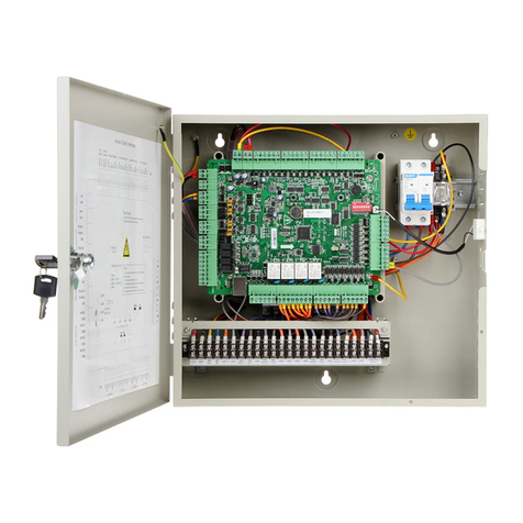
This is a Quick Setup Guide for Ness Version of Hikvision DS-K2 04 4 Door Access Controllers.
For full details refer Ness Full User Manual
Safety Instruction
WARNING
Please note: There is high voltage (240VAC) inside the housing of the controller. Extreme caution
should be taken and only installed and serviced by licensed trained installers.
Table of Contents
DS-K2604 Terminal Description ............................................................................................................ 3
DS-K2604 External Terminals ............................................................................................................... 3
Card Reader Installation ............................................................................................................. 7
The Connection o Wiegand Card Reader ............................................................................................ 7
Installing E-Lock ......................................................................................................................... 7
Activating the Access Control Terminal ....................................................................................... 8
Activating via SADP Software...................................................................................................... 8
Client Operation ......................................................................................................................... 9
Function Module ........................................................................................................................ 9
User Registration and Login ...................................................................................................... 10
Access Control Wizard
1
st
Step - add the Access Controller to iVMS4200 .................................................................... 11
2
nd
Step - add a ‘User / Card’ .................................................................................................. 12
3
rd
Step – Assigning Permissions (Access Levels) ........................................................................ 14
4
th
Step – Setting up Auto Backup ............................................................................................. 15
5
th
Step – Done – Door Status Monitoring ............................................................................... 15

Access Controller·
··
·User Manual
3
DS-K2604 Terminal Description
DS-K2 04 External Terminals
DS-K2604 Terminal descriptions are as ollows:
No. DS-K2604
A1 Power Supply
o E-Lock
GND Grounding
A2 +12V Power Supply o E-Lock Output
A3 Power Supply
o Card Reader
GND Grounding
A4 +12V Power Supply o Card Reader Output
A5
Wiegand Card
Reader 4
GND Grounding
A6 W0 Wiegand Card Reader Data Input Data0
A7 W1 Wiegand Card Reader Data Input Data1
A8 BZ Buzzer o Card Reader Control Output

Access Controller·
··
·User Manual
4
No. DS-K2604
A9 ERR Cresset o Card Reader Control Output (Invalid
Card Output)
A10 OK Cresset o Card Reader Control Output (Valid Card
Output)
A11
Wiegand Card
Reader 3
GND Grounding
A12 W0 Wiegand Card Reader Data Input Data0
A13 W1 Wiegand Card Reader Data Input Data1
A14 BZ Buzzer o Card Reader Control Output
A15 ERR Cresset o Card Reader Control Output (Invalid
Card Output)
A16 OK Cresset o Card Reader Control Output (Valid Card
Output)
A17
Wiegand Card
Reader 2
GND Grounding
A18 W0 Wiegand Card Reader Data Input Data0
A19 W1 Wiegand Card Reader Data Input Data1
A20 BZ Buzzer o Card Reader Control Output
A21 ERR Cresset o Card Reader Control Output (Invalid
Card Output)
A22 OK Cresset o Card Reader Control Output (Valid Card
Output)
A23
Wiegand Card
Reader 1
GND Grounding
A24 W0 Wiegand Card Reader Data Input Data0
A25 W1 Wiegand Card Reader Data Input Data1
A26 BZ Buzzer o Card Reader Control Output
A27 ERR Cresset o Card Reader Control Output (Invalid Card
Output)
A28 OK Cresset o Card Reader Control Output (Valid Card
Output)
B1
Arming Region
Input
Z1 Arming Region Access Terminal 1 (Only or Linkage o
Alarm Relay Output)
B2 GND Grounding
B3 Z2 Arming Region Access Terminal 2 (Only or Linkage o
Alarm Relay Output)
B4 Z3 Arming Region Access Terminal 3 (Only or Linkage o
Alarm Relay Output)
B5 GND Grounding
B6 Z4 Arming Region Access Terminal 4 (Only or Linkage o
Alarm Relay Output)
B7 E-Lock 1 D1+ Door 1 Door Relay Input (Dry Contact)
B8 D1-
B9 E-Lock 2 D2+ Door 2 Door Relay Input (Dry Contact)
B10 D2-

Access Controller·
··
·User Manual
5
No. DS-K2604
B11 E-Lock 3 D3+ Door 3 Door Relay Input (Dry Contact)
B12 D3-
B13 E-Lock 4 D4+ Door 4 Door Relay Input (Dry Contact)
B14 D4-
B15
Door Magnetics
Input
S1 Door 1 Magnetic Detector Input
B16 GND Signal Grounding
B17 S2 Door 2 Magnetic Detector Input
B18 S3 Door 3 Magnetic Detector Input
B19 GND Signal Grounding
B20 S4 Door 4 Magnetic Detector Input
B21
Door Button
B1 Door 1 Door Button Input
B22 GND Signal Grounding
B23 B2 Door 2 Door Button Input
B24 B3 Door 3 Door Button Input
B25 GND Signal Grounding
B26 B4 Door 4 Door Button Input
C1 Power +12V DC12V Cathode
C2 GND Grounding
C3 Battery BAT+ DC12V Battery Cathode
C4 BAT- DC12V Battery Anode
C5
Card Reader
RS485
RS 485A+ Card Reader RS485A+
C6 RS 485A- Card Reader RS485A-
C7 GND Grounding
C8 RS 485B+ Card Reader RS485B+
C9 RS 485B- Card Reader RS485B-
C10 GND Grounding
C11
Access
Controller
RS485
RS 485C+ Uplink RS485+Communication
C12 RS 485C- Uplink RS485-Communication
C13 GND Grounding
C14 RS 485D+
Reserved C15 RS 485D-
C16 GND
C17
Alarm Output
NO/NC1 Alarm Relay 1 Output (Dry Contact)
C18 COM1
C19 NO/NC2 Alarm Relay 2 Output (Dry Contact)
C20 COM2
C21 NO/NC3 Alarm Relay 3 Output (Dry Contact)
C22 COM3
C23 NO/NC4 Alarm Relay 4 Output (Dry Contact)
C24 COM4
D1
Event Input
C8 Event Alarm Input 8
D2 GND Grounding
D3 C7 Event Alarm Input 7

Access Controller·
··
·User Manual
6
No. DS-K2604
D4 C6 Event Alarm Input 6
D5 GND Grounding
D6 C5 Event Alarm Input 5
D7 C4 Event Alarm Input 4
D8 GND Grounding
D9 C3 Event Alarm Input3
D10 C2 Event Alarm Input 2
D11 GND Grounding
D12 C1 Event Alarm Input 1
Notes:
The Alarm input hardware inter ace is normally open by de ault. So only the normally open
signal is allowed. It can be linked to the buzzer o the card reader and access controller, and
the alarm relay output and open door relay output.
RS485 card ID should be set as 1 to 8. For example, the ID o door 1 is 1 and 2 standing or in
and out respectively.
For single-door access controller, the Wiegand card reader 1 and 2 respectively correspond to
the entering and exiting card readers o door 1.

Access Controller·
··
·User Manual
7
Card Reader Installation
The Connection of Wiegand Card Reader
Note: Minimal wiring required is 4 Wire (+12VDC, Gnd, W0 and W1)
Optionally you may connect the OK/ERR/BZ, or when wanting to control the LED and buzzer o
the Wiegand card reader.
Recommended wiring method is RS485 instead o Wiegand.
Installing E-Lock
Set the link under the Lock relay to suit lock.
Installation o Fail Secure / Power to Unlock.
Installation o Fail Sa e / Power to Lock.

Access Controller·
··
·User Manual
8
Activating the Access Control Terminal
Purpose:
You are required to activate the terminal irst be ore using it.
Activation via SADP, and Activation via client so tware are supported.
The de ault values o the control terminal are as ollows.
The de ault IP address: 192.0.0.64.
The de ault port No.: 8000.
The de ault user name: admin.
Activating via SADP Software
SADP so tware is used or detecting the online device, activating the device, and resetting the
password.
Get the SADP so tware rom the supplied disk or the o icial website, and install the SADP
according to the prompts. Follow the steps to activate the control panel.
Steps:
1. Run the SADP so tware to search the online devices.
2. Check the device status rom the device list, and select an inactive device.
3. Create a password and input the password in the password ield, and con irm the password.
STRONG PASSWORD RECOMMENDED– We highly recommend you create a strong
password of your own choosing (using a minimum of 8 characters, including upper
case letters, lower case letters, numbers, and special characters) in order to increase
the security of your product. And we recommend you reset your password regularly,
especially in the high security system, resetting the password monthly or weekly can
better protect your product.
4. Click Activate to activate the device.
5. Check the activated device. You can change the device IP address to the same network
segment with your computer by either modi ying the IP address manually or checking the
checkbox o Enable DHCP.
6. Input the password and click the Modify button to activate your IP address modi ication.

Access Controller·
··
·User Manual
9
Client Operation
You can set and operate the access control devices via the client so tware. This chapter will
introduce the access control device related operations in the client so tware. For integrated
operations, re er to User anual of iV S-4200 Client Software.
We recommend using iVMS4200 Version V2.7.1.4 Build 20180403 (or later)
Function Module
Control Panel of iVMS-4200:
For the irst time running the so tware, you can click on the
Control Panel to select the modules to display on the Operation and Control area o the control
panel.
Select the required module, including ‘Access Control’ and ‘Status Monitor’ options.
Note:
The irst time opening the Access Control module,
you will be promoted i the system is ‘Non-Residence’
or ‘Residence’ application.
The only di erence is i you choose ‘Residence’
application you cannot use Time & Attendance
options at a later date.
We recommend selecting “Non-Residence”
Once selected you CANNOT change at a later date.!

Access Controller·
··
·User Manual
10
User Registration and Login
For the irst time to use iVMS-4200 client so tware, you need to register a new super user or login.
When opening iVMS-4200 a ter registration, you can log into the client so tware with the
registered user name and password.
Steps:
1. Input the user name and password you registered.
Note: I you orget your password, please click Forgot Password and remember the encrypted
string in the pop-up window. Contact your dealer and send the encrypted string to him to reset
your password.
2. Optionally, check the checkbox Enable Auto-login to log into the so tware automatically.
3. Click Login.
A ter running the client so tware, (Or at any time by clicking on ‘Help’ / Open Access Control and
Video Intercom Wizard”) you can open the wizards (including access control and video intercom
wizard), to guide you to add the device and do other settings and operations.

Access Controller·
··
·User Manual
11
Access Control Wizard.
Step 1.
Adding the ‘Access Controller’ online into iVMS4200
Ensure the Access controller is ‘Activated’ via SADP tool (or via iVMS4200)
From the ‘Online Device’ window select the controller and then click on ‘Add to Client’
Give it a name (e.g. Controller on 2
nd
Floor) then add the username and password (password is the
one allocated when activating the controller) and click add.
Controller will then be added to ‘Device or Management’ window.
Then click ‘Next’

Access Controller·
··
·User Manual
12
Step 2.
Adding a person User Card
First step is to add a ‘group’ organisation or the user(s)
Click on Add on the ar le t o screen.
Once an Organisation is added click on ‘Add’ Person to add a card holder
Add a name to the
person you wish to
add, along with any
other data
(optional) and click
‘Save and Continue’.
Then Click
‘Credential’
Then click on ‘Add’
to add an Access
Card to this user.

Access Controller·
··
·User Manual
13
Select Card Type = Normal
To add a card or this person it can be
added 3 ways.
1. Via any Access Reader on the
system,
2. Via a card Enrollment Reader,
3. By manually entering the card
No.
To auto read the card into the system
rom a card reader in the system, leave
the option set to ‘Card Reader Mode’ /
Access Control’ and then rom the drop
down box select a reader you wish to
learn the card into the system rom.
Once the reader you will use to learn
the card into the system is selected,
click on “Read” then take a new card
and present it to the select reader to
learn it into the database.
Once the card is presented and read at the selected reader, the card will be displayed at the
bottom part o the ‘window’. Click on ‘Stop Reading’ to take the reader out o card read
mode.
Then Click on “OK” to register this card to the user.

Access Controller·
··
·User Manual
14
Step 3.
Assigning Permissions to the user
Be ore a card will work ‘permissions’ (Access Levels (i/e what doors can the card user during what
times)
Click ‘Next’ to move to ‘Add Permissions’.
Click on ‘Add’ to add a new Access Permission.
1. Give the permission Group to
be added a name (e.g. Full
Access).
Under the name is a ‘Time
Schedule template’ with a
de ault ‘Whole Week
Template’ as de ault (i.e. 7
Days 24 Hours)
2. Expand the ‘Person’ ield to
display all users in the system
and expand the Access
controller(s) to show all doors
in the system.
3. Select the users you want to
assign this Permission (Access
Level) to and click on the ‘add
selected users “>” option
4. Select what door(s) the user
can have access to (e.g. All
Doors) and click on the ‘add
selected door(s) “>” option
The card should now be working and unlocking all
doors (or selected doors as selected in point 4 above)
when presented to the reader(s)

Access Controller·
··
·User Manual
15
Step 4.
Auto Backup
Click ‘Next’ and select i ‘auto Backup’ o the database is required and i so what days and time the
Auto Backup o iVMS4200 database will take place.
Note: As de ault the backup location is C:/iVMS-4200. It is advisable to change this de ault location
to a di erent drive to that o C: Drive. (e.g. Google Drive or USB Drive) so i the hard drive ails all
data will not be lost.!
Step 5.
Done – go to Door Status Monitor
Once the quick setup wizard is complete click on ‘Door Status Monitoring’
This will open the ‘Status Monitor’ module where you can view and manage the status o doors on
your controller.
You can select a door(s) and click on ‘open door’ to manually unlock the door.
By Selecting the ‘Card Swiping Record’ tab all access events will be displayed as cards are presented
to readers.

Access Controller·
··
·User Manual
16
This manual has been modi ied by Ness Corporation or our valued customers.
www.nesscorporation.com
For support contact Ness Customer Support
customerservice@ness.com.au
This manual suits for next models
1
Table of contents
Other Ness IP Access Controllers manuals
