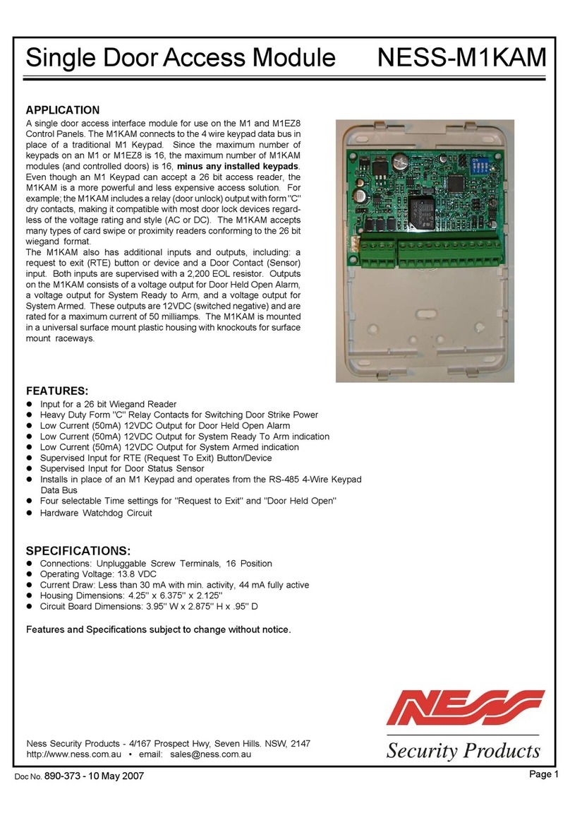
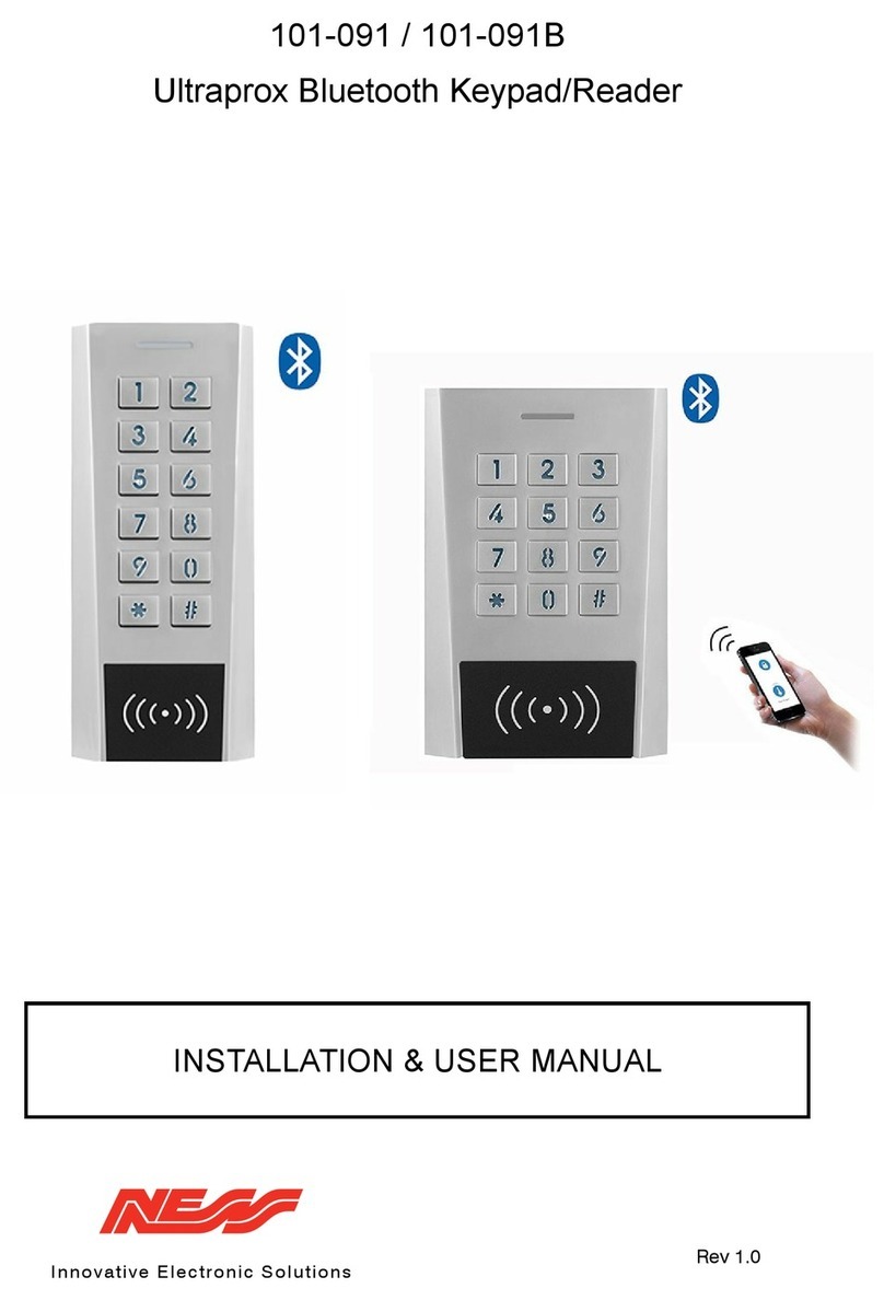
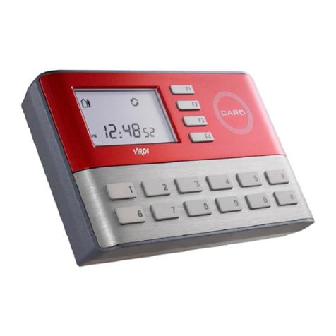
Ness ID Teck 505R User manual

1
IDTeck
505R
Rev. 5.0
USER’S MANUAL

101-046 2 FGR006 – Version 3.0
IDTeck - 505R - 1 DOOR ACCESS CONTROLLER
TableofContents
1. IMPORTANT SAFETY INSTRUCTIONS
2. INTRODUCTION
2.1 IDENTIFYING SUPPLIED PARTS
2.2 ABOUT NESS - IDTECK 505R
2.3 SPECIFICATION
3. PRODUCT OVERVIEW
3.1 FUNCTIONS
3.2 PRODUCT EXPLANATION
3.2.1 FRONT PANEL DESCRIPTION
3.2.2 WIRE COLOR TABLE OF THE NESS - IDTECK 505R
4. INSTALLATION TIPS & CHECK POINT
4.1 CHECK POINTS BEFORE INSTALLATION
4.1.1 SELECTION OF CABLE
4.1.2 RECOMMENDED CABLE TYPE AND PERMISSIBLE
LENGTHOFCABLE
4.2 CHECK POINTS DURING INSTALLATION
4.2.1 TERMINATION RESISTOR
4.2.2 HOW TO CONNECT TERMINATION RESISTORS
4.2.3 GROUNDING SYSTEM FOR COMMUNICATION CABLE
4.2.4 REVERSE DIODE CONNECTION
5. INSTALLATION
5.1 DIMENSIONS
5.2 BACKUP BATTERY DIP SWITCH
5.3 SYSTEM INITIALIZATION
5.4 INSTALLATION OF THE PRODUCT
5.5 WIRING
5.5.1 POWER
5.5.2 INPUT CONNECTIONS
5.5.3 OUTPUT CONNECTIONS
5.5.4 EXTRA READER CONNECTIONS
6. COMMUNICATIONS
6.1 RS232 COMMUNICATION PORT CONNECTION
6.2 RS-422 COMMUNICATION PORT CONNECTION
6.2.1 RS-422 COMMUNICATION (STANDALONE)
6.2.2 RS-422 COMMNUNICATION
(MULTIPLE 505R CONNECTIONS)
6.3 DIAL UP MODEM
6.4 TCP/IP CONVERTER (EXTERNAL VERSION)

101-046 3 FGR006 – Version 3.0
IDTeck - 505R - 1 DOOR ACCESS CONTROLLER
7. BASIC SETTINGS
7.1 INITIALIZATION OF 505R
7.2 HOW TO ENTER THE SETUP MENU
7.3 DATE AND TIME SETTING
7.4 ID COUNT SETTING
7.5 ID REGISTRATION
8. OPERATION
8.1 NORMAL OPERATION
8.2 DEFAULT SETTING
9. SETTING CHANGES
9.1 SETUP MENU F1
9.2 SETUP MENU F2
9.3 SETUP MENU F3
9.4 SETUP MENU F4
APPENDIX
A. THE RELATION BETWEEN INPUT AND
OUTPUT (DEFAULT)
B. TROUBLE SHOOTING
FCC REGISTRATION INFORMATION
CONTACTS
TEMPLATE

101-046 4 FGR006 – Version 3.0
IDTeck - 505R - 1 DOOR ACCESS CONTROLLER
1. IMPORTANT SAFETY INSTRUCTIONS
To prevent injuries to persons and damages to property, please read all instructions and follow them
whenever you deal with this product.
After reading, please put this instruction manual where it can be easily seen for the system operator.
ON INSTALLATION AND POWER
Use 12V DC power ONLY.
- Connecting to higher than 12V DC may result in a risk of electric shock, fire, or heavy damage of the
unit.
Do NOT install this product at places with wet or metallic dust or that can be watered.
- There may be risks of electric shock and fire.
Do NOT install this product near electric motors running.
- The Unit may not operate normally.
Do NOT set this product near heaters or any thing that produces heat.
- There may be a risk of fire.
Be ALWAYS careful not to short-circuit any part of the circuitry with tools like a screwdriver.
- There may be a risk of fire or heavy damage of the unit.
ON MAINTENANCE
Do NOT use any kind of liquid for cleaning.
- There may be a risk of electric shock, fire or heavy damage of the unit. Use air spray, if needed.
Users are cautioned NOT to attempt repair of this product or modify the wirings set by the installer at their
own discretion.
- It may pose the risk of fire, hardware damages, or abnormal operations of the unit.
It is recommended not to use a flammable spray or something else easy flammable near this product.
- There may be the risk of an explosion or fire.
Keep the unit away from any unauthorized people.
- It may cause abnormal operations of the unit.

101-046 5 FGR006 – Version 3.0
IDTeck - 505R - 1 DOOR ACCESS CONTROLLER
NOTICE
Please contact a designated service centre or the outlet at which the product was purchased when
A. Any liquid has been spilt or sprayed onto the product. In this case, cut the power off first.
B. The product seems to be operating abnormally.
C. The unit exhibits a distinct change in performance.
D. The unit has fallen to be broken down or damaged on its case.
* Repairing costs can be charged for troubles caused due to improper handling or negligence of users or the
operator.

101-046 6 FGR006 – Version 3.0
IDTeck - 505R - 1 DOOR ACCESS CONTROLLER
2. INTRODUCTION
2.1 IDENTIFYING SUPPLIED PARTS
Please unpack and check the contents of the box (Optional accessories, if purchased, may be included in the
package).
Main unit Wall mount O-ring Manual Diode
( 1ea ) ( 1ea ) ( 5ea ) ( 1ea ) ( 2개 )
2.2 ABOUT NESS - IDTECK 505R
The NESS - IDTECK505R is a highly advanced, intelligent single door controller with a dual 8bit
microprocessor to meet the market requirement for a robust integrated solution for access control and time
& attendance. It is designed for low cost as well as high security, convenience and reliability. This user-
friendly device allows you to register 500 ~ 10,000 ID numbers and can keep 2,500 ~ 7,250 events.
Number of ID & Events can be exchanged under the ratio of 2 to1, which means every 500 users can be
converted to 250 events. The Event buffer reports and archive information to Excel or Access databases and
ultimately manage all access control and time & attendance issues. With a built-in 4” inch RF reader and
keypad for Personal Identification Numbers (PIN), the NESS - IDTECK505R offers up to two levels of ID
verification. You can verify by Proximity Card, PIN or both and multiple verification levels can be custom
programmed for each user or user group. Four independent input ports can be utilized for a wide variety of
controls including exit buttons, door contacts, PIR sensors and fire detection equipment. Actions to be taken
and time settings can be programmed with the front keypad or via the intuitive Windows-based software
program. The NESS - IDTECK505R can be used both as a stand-alone system and also be networked. All
control setting values such as ID numbers, inputs/outputs, real-time clock, time schedules, and event
transaction reports can be uploaded and/or downloaded to and from the host computer. The compact and
contemporary unit is easily installed and programming requires no significant knowledge of access control
or time & attendance. The three LED indicator lights inform you of the systems operating status at real time
and the digital display acts as a programming aid as well as a regulation time clock. By bundling the
ultimate in high security access control and comprehensive employee management tools into a compact
user-friendly unit, the field proven NESS - IDTECK505R is the ideal solution for controlling entrances and
ensuring complete employee accountability.

101-046 7 FGR006 – Version 3.0
IDTeck - 505R - 1 DOOR ACCESS CONTROLLER
2.3 SPECIFICATION
CPU 8bit Microprocessor
Memory Program Memory: 64KB ROM
Data Memory: 128KB RAM (battery backup)
Power DC 12V/ 350mA max. (Excluding lock current)
Card Holders
/ Event Buffers
User programmable by 500 units of card holders
Card Holders: 500 ~ 10,000 users (Default: 5,000 users)
Event Buffers: 2,500 ~ 7,250 events (Default: 5,000 events)
Reader Ports 1 External port, 1 Internal port / Wiegand format
Reader Data Format Standard 26 bits Wiegand Format,
Standard 34 bits Wiegand Format (Applied to SR505),
8 bits burst Format for keypad reader
Communication port RS232/RS422 (up to 32 channels) selectable
4800, 9600(Default), 19200, 38400bps communication speed
Inputs/Outputs 4 Input ports/ DC12V/ 20mA
2 Relay Output ports/ DC12V~24V/ FORM-C Relay 2A max.
2 TTL Output ports: DC5V/ 20mA
Self Diagnosis Yes
Reset Power on reset and Watchdog timer reset
Operation Status 3 LED (Red, Green, Yellow) indicators
Operating Environment 0°C ~ +65°C, 0 ~ 90%(Humidity)
Weight 400g
Dimensions 150mm(5.9 ”) x120mm (4.72 ”) x39.5mm (1.55 ”)
Keypad 16 keys
LCD Display Module 2Lines x 16ch, 2.62” x 0.55”(65.6mm x 13.8mm) viewing area
NESS - IDTECK 505R Series
NESS - IDTECK 505R Built-in 125KHz (PSK) Reader
NESS - IDTECK SR505
Built-in 13.56MHz(MIFARE○R) Reader
IP-505R Built-in 125KHz(ASK) Reader

101-046 8 FGR006 – Version 3.0
IDTeck - 505R - 1 DOOR ACCESS CONTROLLER
3. PRODUCT OVERVIEW
3.1 FUNCTIONS
Stand-Alone Operation
The NESS - IDTECK 505R is capable of having 2 readers (1 Door Control). The unit receives card ID
numbers from the proximity readers and determines whether or not to unlock the door. When an input
signal is entered, for example from a Sensor activated or an Exit button pressed, the controller generates
and logs an appropriate response by input signals. All events are stored into the memory buffers and sent to
the host computer. The access controller is a true stand-alone device that, in the event of malfunction, will
not affect other units when used in conjunction with one another.
Operation with Host Computer
All event transactions can be managed via the host computer. The data transmitted from the controller can
be displayed and stored on the host PC.
Data Backup
The controller retains all user information and event data for 30 days, even in the case of power failure.
CAUTION: Battery switch must be set correctly before the unit running.
(See the INSTALLATION section)
Keypad
If the NESS - IDTECK 505R is not connected to a host PC, the integrated keypad and LCD display module
can also be used for the entire programming process.
Anti-Pass-Back
By using an additional proximity reader, the Anti-Pass-Back mode can be set. The Anti-pass-back mode
prevents entry or exit when the registered user did not properly followed one entry and one exit by the Anti-
pass-back rule. The same user cannot enter twice with the entry card without properly using the exit before.
Input/Output
The NESS - IDTECK 505R has 4 built-in inputs and 4 outputs (2 relay outputs and 2 TTL outputs), which
can be used to manipulate a wide variety of controls.
Time Schedule Setup
You can program 10 time schedules and apply one time schedule to each User. Each time schedule has 8
different time zones from Monday-Sunday (7 time zones) and one holiday. Each time zone has 5 different
time codes so you can program 5 different time codes to each day. You can also program time schedules for
individual inputs and outputs. Note that the time schedule for input is activated time code for input device
so that the input is activated during the time code on this time schedule. Each time schedule is linked to one
holiday schedule and this linked holiday only validates to the holiday time code of the time schedule.

101-046 9 FGR006 – Version 3.0
IDTeck - 505R - 1 DOOR ACCESS CONTROLLER
Holiday Schedule Setup
Excepting Sunday, you can program 32 holidays to one holiday schedule. Each holiday schedule is linked
to one time schedule, which has a time code for holidays. You can program all holidays to a holiday
schedule and the time code for holidays is programmed to the holiday time zone of time schedule.
Example: A. Holiday schedule 01 linked to time schedule 01,
Holiday schedule 02 linked to time schedule 02
B. Holiday schedule 02 linked to time schedule 01,
Holiday schedule 01 linked to time schedule 03
Forced Door Open Alarm
When the door is opened by force, the door contact sensor will be activated. The forced door open alarm
will be generated until the door is closed again. For this application, you have to install the door contact
sensor and properly set the door contact time and outputs to the alarm devices.
Duress Alarm
In case of duress, enter the 2 digits Duress Password and press the<ENT> key before the normal access
process. The door can be opened as normal, but the duress alarm is also generated at the same time. The
duress alarm output will be activated to the TTL output and an alarm event will be sent to the host PC.

101-046 10 FGR006 – Version 3.0
IDTeck - 505R - 1 DOOR ACCESS CONTROLLER
3.2 PRODUCT EXPLANATION
3.2.1 FRONT PANEL DESCRIPTION
Figure: Description of NESS - IDTECK 505R Front Panel
LCD Module:
LCD module display 505R status.
System Operation Status LED:
When the power is applied to 505R, the red LED is turned on.
When the Relay #1 is operated, the green LED is turned on.
When the Relay #2 is operated, the yellow LED is turned on.
16 keypad:
You can operate 505R manually by using the keypad.
Function key:
The 505R has four Function keys ([F1], [F2], [F3], [F4]).
Card reading status LED:
When a card is read, the card reading status LED turns on green.
16 key pad Function key
Card Reading
Status LED
LCD
System Operation
Status LED

101-046 11 FGR006 – Version 3.0
IDTeck - 505R - 1 DOOR ACCESS CONTROLLER
3.2.2 WIRE COLOR TABLE OF THE NESS - IDTECK 505R
I/O PORT NAME SIGNAL NAME WIRE COLOR
POWER
Main Power (+12V +12V Red wire
Power Ground 0V Black wire
OUTPUT
Door RELAY (COM) COM (1) Grey wire with red stripe
Door RELAY (NC) NC (1) Blue wire with white stripe
Door RELAY (NO) NO (1) White wire with red stripe
Alarm RELAY (COM) COM (2) White wire
Alarm RELAY (NC) NC (2) Purple wire with white stripe
Alarm RELAY (NO) NO (2) Purple wire
TTL OUTPUT #1 TTL 1 Brown wire with white stripe
TTL OUTPUT #2 TTL 2 Orange wire with white stripe
INPUT
Exit Button EXIT Orange wire
Door Sensor CONTACT Yellow wire with red stripe
Aux Input #1 IN#1 Green wire
Aux Input #1 IN#2 Green wire with white stripe
EXTRA READER
Wiegand DATA 0 DATA0 Pink wire
Wiegand DATA 1 DATA1 Cyan wire
RS232
RS232-TX TXD Black wire with white stripe
RS232-RX RXD Red wire with white stripe
RS422
RS 422-TX (-) TXD (-) Yellow wire
RS422-TX (+) TXD (+) Grey wire
RS422-RX (-) RXD (-) Blue wire
RS422-RX (+) RXD (+) Brown wire

101-046 12 FGR006 – Version 3.0
IDTeck - 505R - 1 DOOR ACCESS CONTROLLER
4. INSTALLATION TIPS & CHECK POINT
Installing the NESS - IDTECK 505R is an easy task. It can be installed with common hand tools and readily
available communications wires. This section provides information about wiring, wire runs and other information
to make the installation quick and easy.
4.1 CHECK POINTS BEFORE INSTALLATION
4.1.1 SELECTION OF CABLE
System installation cabling will be configured as follow.
Figure: System Installation Layout

101-046 13 FGR006 – Version 3.0
IDTeck - 505R - 1 DOOR ACCESS CONTROLLER
4.1.2 RECOMMENDED CABLE TYPE AND PERMISSIBLE LENGTH OF CABLE
Reference Description Cable Specification
Maximum
Distance
①505R Power (DC12V)
DC Power -> 505R
Belden #9409, 18 AWG
2 conductor, unshielded 30m
Belden #9512, 22 AWG
4 conductor, shielded
②*Reader (Power and Data)
Extra Reader -> 505R Belden #9514, 22 AWG
8 conductor, shielded
150m
Belden #9512, 22 AWG
4 conductor, shielded
③
Door Contact
Exit Button
Sensor Input
Input -> 505R
Belden #9514, 22 AWG
8 conductor, shielded
300m
④Door Lock, Alarm Device
Lock (Alarm) -> 505R
Belden #9409, 18AWG
2 conductor, unshielded 300m
⑤RS232 Cable
Converter -> Host P.C.
Belden #9829, 24 AWG
2-twisted pair, shielded 15m
RS485 Cable
505R -> 505R
505R -> Converter
Belden #9829, 24 AWG
2-twisted pair, shielded
⑥RS422 Cable
505R -> 505R
505R -> Converter
Belden #9830, 24 AWG
3-twisted pair, shielded
1,200m
*: Need thicker wire if you connect the reader with high current consumption.
4.2 CHECK POINT DURING INSTALLATION
4.2.1 TERMINATION RESISTOR
Termination resistors are used to match impedance of the network to the impedance of the transmission line
being used. When impedance is mismatched, the transmitted signal is not completely absorbed by the
receiver and a portion of signal is reflected back into the transmission line.
The decision whether or not to use termination resistors should be based on the cable length and data rate
used by the communication system.
For example, if you use 9,600 baud rate and 1,200m length of cable, the propagation velocity of cable is
0.66 x speed of light (This value is specified by the cable manufacturer), if we assume the reflections will

101-046 14 FGR006 – Version 3.0
IDTeck - 505R - 1 DOOR ACCESS CONTROLLER
damp out in three round trip up and down the cable length, the transmitted signal will stabilize 18.6us after
the leading edge of a bit. Since the data bit is captured in the middle of the bit, which is approximately 52us
after the leading edge of a bit. The reflection stabilizing time 18.6us is much before the centre of the bit
therefore the termination resistors are not required.
However, if you install the cable to maximum length, the impedance of cable and network is mismatched
and the transmitted signal is overlapped by the reflected signal. In this case, it is recommended to add
termination resistors to the end of the receiver lines. A 120Ωresistor can be used for termination resistor in
parallel between the receiver lines “A” and “B” for 2 wires RS485 system or “RX+” and “RX-” for 4 wires
RS422 system. A termination resistor of less than 90Ωshould not be used and no more than 2 terminations
should be used in one networking system.
4.2.2 HOW TO CONNECT TERMINATION RESISTORS
Figure: Termination resistors for 2 wires RS485 communication system
Figure: Termination resistors for 4 wires RS422 communication system
4.2.3 GROUNDING SYSTEM FOR COMMUNICATION CABLE
We recommend to using proper grounding system on the communication cable. The best method for
grounding system is to put the shield wire of the communication cable to the 1st class earth grounding;
however it is not so easy to bring the earth ground to the communication cable and also the installation cost
is raised.
There will be three grounding point where you can find during installation;
1) Earth Ground
2) Chassis Ground
3) Power Ground
The most important point for grounding system is not to connect both ends of shield wires to the grounding
system; in this case there will be a current flow through the shield wire when the voltage level of both ends
of shield wire is not equal and this current flow will create noise and interfere to communications.

101-046 15 FGR006 – Version 3.0
IDTeck - 505R - 1 DOOR ACCESS CONTROLLER
For the good grounding, we recommend to connecting ONLY one end of shield wire of communication
cable to grounding system; If you find earth ground nearby, then connect one end of shield wire to earth
ground; If you do not have earth ground nearby, then find chassis ground and connect one end of shield
wire to chassis ground; If you do not find both earth ground and chassis ground, then connect one end of
shield wire to power ground. (GND of 505R)
Note that if the chassis ground is not properly connected to the earth and floated from the ground level, then
grounding to the chassis ground will give the worst communication; in this case we recommend to using
power ground instead of chassis ground.
Figure: Grounding system
4.2.4 REVERSE DIODE CONNECTION
If you connect an inductor (Door Locks or Alarm device) to the output relays, there will be a high surge
voltage created while the inductor is turning on and off. If you do not connect reverse diode, the surge
voltage will transfer and damage to the electronic circuit of the controller. It is strongly recommended to
add a reverse diode between the inductor coils to absorb this surge voltage.
Figure: Reverse Diode connection

101-046 16 FGR006 – Version 3.0
IDTeck - 505R - 1 DOOR ACCESS CONTROLLER
5. INSTALLATION
5.1 DIMENSIONS Unit: mm (inch)
150mm (5.9 ”) x 120mm (4.72 ”) x 39.5mm (1.55 ”)
5.2 BACKUP BATTERY DIP SWITCH
NESS - IDTECK 505R has a switch for the backup battery connection, which remains open circuit to
prevent any current consumption of the backup battery (Figure: Switch setting). Before the NESS -
IDTECK 505R operation, it needs to be connected so that the backup battery can retain the memory during
power failure.
Fi
gure: DIP SWITCH SETTING Figure: DIP SWITCH LOCATION
5.3 SYSTEM INITIALIZATION
Connect the cyan wire, pink wire and black wire (they are seen from the rear view) together and power on
the unit. If you want hardware initialization, press enter key <1>. After initializing – switch main power
OFF, separate the three wires (pink, cyan and black (GND)) and switch the main power ON again.

101-046 17 FGR006 – Version 3.0
IDTeck - 505R - 1 DOOR ACCESS CONTROLLER
5.4 INSTALLATION OF THE PRODUCT
5.4.1. Tear off page 56 and use the provided template to drill two 6-32 holes and one 1/2" hole on the
proper location of the wall to mount the Wall Mount bracket as shown below.
(Skip this step if the gang box is already installed on the wall.)
5.4.2 Using 2 screws, install wall mount to the wall.

101-046 18 FGR006 – Version 3.0
IDTeck - 505R - 1 DOOR ACCESS CONTROLLER
* CAUTION *
Before mounting the NESS - IDTECK 505R unit to the Wall Mount bracket, operational test of the unit
should be completed, as the locking pins will lock the unit to the Wall Mount. Removing the unit from the
Wall Mount bracket after they have been installed together may cause damages to the bracket and render its
effectiveness.
5.4.3 Insert 5 O-rings to the wall mount as indicated, then route the cable of the main unit through the
center hole and push the main unit to wall mount to lock the main unit and make sure that the main unit is
locked with wall mount.
5.5 WIRING
5.5.1 POWER
Connect (+) wire of DC 12V power to the Red wire.
Connect GND (-) wire of DC 12V power to the Black wire.
5.5.2 INPUT CONNECTIONS
Exit Button Connection
- Connect one wire from an Exit Button to the Orange wire.
- Connect the other wire from the Exit Button to the GND.
Door Contact Sensor Connection
- Connect one wire from a Door Contact Sensor to the Yellow wire with Red stripe.
- Connect the other wire from the Door Contact Sensor to GND.
Auxiliary Input Connection
(Applied to Aux Input #1(Green wire), Aux Input #2(Green wire with White stripe))
- Connect one wire from an Auxiliary Input Device to one of the Input #1, #2.
- Connect the other wire from the Auxiliary Input Device to GND.
Figure: INPUT DEVICES CONNECTION

101-046 19 FGR006 – Version 3.0
IDTeck - 505R - 1 DOOR ACCESS CONTROLLER
5.5.3 OUTPUT CONNECTIONS
Door Lock (Power Fail Safe) Connection (Relay #1)
- Connect COM wire of Relay #1, the Gray wire with Red stripe to +12V.
- Connect NC wire of Relay #1, the Blue wire with White stripe to (+) wire of door lock
device.
- Connect GND wire to (-) wire of door lock devices.
Door Lock (Power Fail Secure) Connection (Relay #1)
- Connect COM wire of Relay #1, the Gray wire with Red stripe to +12V.
- Connect NO wire of Relay #1, the White wire with Red stripe to (+) wire of door lock device.
- Connect GND wire to (-) wire of door lock devices.
Alarm Device Connection (Relay #2)
1. Connect COM wire of Relay #2, the White wire to +12V.
2. Connect NO wire of Relay #2, the Purple wire to (+) wire of Alarm devices.
3. Connect GND port to (-) wire of Alarm devices.
Figure: DOOR LOCK, ALARM DEVICE CONNECTION
CAUTION: Please add one DIODE as shown above.
DIODE: Fast recovery DIODE (current: Min. 1A), 1N4001 ~ 1N4007 or similar.
5.5.4 EXTRA READER CONNECTIONS
Proximity Reader Connection
1. Connect (+) wire of the Proximity Reader to DC +12V.
2. Connect (-) wire of the Proximity Reader to GND of Power.
3. Connect Data-0 wire of the Proximity Reader to D0, the Pink wire.
4. Connect Data-1 wire of the Proximity Reader to D1, the Cyan wire.

101-046 20 FGR006 – Version 3.0
IDTeck - 505R - 1 DOOR ACCESS CONTROLLER
zCompatible Readers:
505R/iP-505R: Standard 26bit Wiegand Format Proximity Readers.
Standard 26bit Wiegand+8bit Burst Format Proximity and Keypad Readers.
SR505: Standard 34bitWiegand Format Proximity Readers.
Standard 34bitWiegand+8bit Burst Format Proximity and Keypad Readers.
zRecommended Readers:
505R: RF-TINY, RF10, RF20, RF30, RFK101, FGR006, FGR006EX.
iP-505R: iP10, iP20, iP30, iPK101.
SR505: SR10, SR20, SR30, SRK101, FGR006SR, FGR006SRB.
6. COMMUNICATIONS
6.1 RS232 COMMUNICATION PORT CONNECTION
A 9-pin connector (Serial communication connector, female) is required to connect the 505R to a host
computer via RS232 communication. Please follow the instructions.
1. Connect RS232-TX (Black wire with White stripe) wire of 505R to the pin #2(RX) of the 9-pin
connector.
2. Connect RS232-RX (Red wire with White stripe) port of 505R to the pin #3(TX) of the 9-pin
connector.
3.ConnectGND (Black wire) of 505R to the pin #5 of the 9-pin connector.
4. Plug in the 9-pin connector to COM1 or COM2 Port of the host PC.
5. Install and run 505R Application Software.
Figure: RS-232 COMMUNICATON
Table of contents
Other Ness IP Access Controllers manuals
Popular IP Access Controllers manuals by other brands
Avigilon
Avigilon Access Control Manager Enterprise Getting started guide

Kisi
Kisi Reader Pro 2 installation manual
Transmitter Solutions
Transmitter Solutions Dolphin DOLCWIUHF-ER-902 manual
FRIEDHELM LOH
FRIEDHELM LOH Rittal CMC III DK 7030.202 Installation and Short User Guide

L-1
L-1 Bioscrypt V-Station 4G installation guide
Roger
Roger MCT82M SERIES installation manual
