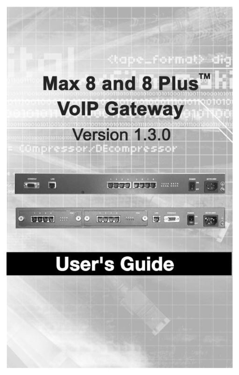
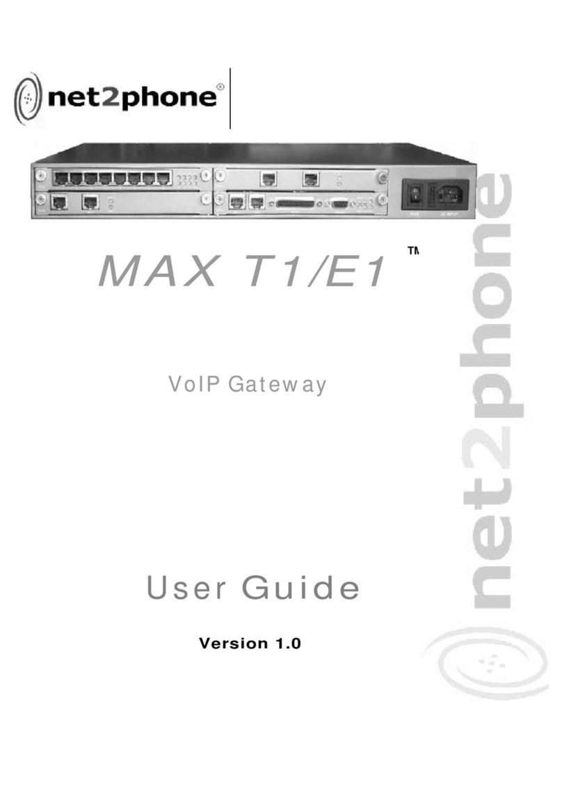
Net2Phone Net2Phone MAX 8/16 User manual

Page 0

The specifications and information regarding the products in this manual are subject to change without notice.
All statements, information, and recommendations in this manual are believed to be accurate but are
presented without warranty of any kind, express or implied. Users must take full responsibility for their
application of any products.
The software license and limited warranty for the accompanying product are set forth in the information packet
that shipped with the product and are incorporated herein by this reference. If you are unable to locate the
software license or limited warranty, contact your Net2Phone representative for a copy.
The following information is for FCC compliance of Class A devices: This equipment has been tested and
found to comply with the limits for a Class A digital device, pursuant to part 15 of the FCC rules. These limits
are designed to provide reasonable protection against harmful interference when the equipment is operated in
a commercial environment. This equipment generates, uses, and can radiate radio-frequency energy and, if
not installed and used in accordance with the instruction manual, may cause harmful interference to radio
communications. Operation of this equipment in a residential area is likely to cause harmful interference, in
which case users will be required to correct the interference at their own expense.
The following information is for FCC compliance of Class B devices: The equipment described in this manual
generates and may radiate radio-frequency energy. If it is not installed in accordance with Net2Phone's
installation instructions, it may cause interference with radio and television reception. This equipment has been
tested and found to comply with the limits for a Class B digital device in accordance with the specifications in
part 15 of the FCC rules. These specifications are designed to provide reasonable protection against such
interference in a residential installation. However, there is no guarantee that interference will not occur in a
particular installation.
Modifying the equipment without Net2Phone's written authorization may result in the equipment no longer
complying with FCC requirements for Class A or Class B digital devices. In that event, your right to use the
equipment may be limited by FCC regulations, and you may be required to correct any interference to radio or
television communications at your own expense.
You can determine whether your equipment is causing interference by turning it off. If the interference stops, it
was probably caused by the Net2Phone equipment or one of its peripheral devices. If the equipment causes
interference to radio or television reception, try to correct the interference by using one or more of the following
measures:
· Turn the television or radio antenna until the interference stops.
· Move the equipment to one side or the other of the television or radio.
· Move the equipment farther away from the television or radio.
· Plug the equipment into an outlet that is on a different circuit from the television or radio. (That is, make
certain the equipment and the television or radio are on circuits controlled by different circuit breakers or
fuses.)
Modifications to this product not authorized by Net2Phone could void the FCC approval and negate your
authority to operate the product.
Notwithstanding any other warranty herein, all document files and software of these suppliers are provided "as
is" with all faults. Net2Phone and the above-named suppliers disclaim all warranties, expressed or implied,
including, without limitation, those of merchantability, fitness for a particular purpose and non-infringement or
arising from a course of dealing, usage, or trade practice.
In no event shall Net2Phone or its suppliers be liable for any indirect, special, consequential, or incidental
damages, including, without limitation, lost profits or loss or damage to data arising out of the use or inability to
use this manual, even if Net2Phone or its suppliers have been advised of the possibility of such damages.
Net2Phone Max , net2phone, and the Net2Phone logo are registered trademarks of Net2Phone, Inc. in the US
and certain other countries. All other trademarks mentioned in this document are the property of their
respective owners.
Max 8/16 and T1/E1 User’s Guide
Rev. 1.5.10 November 2003
Copyright © 2003, Net2Phone, Inc. All rights reserved
The use, disclosure, modification, transfer, or transmittal of this work for any purpose, in any form, or by any
means, without the written permission of Net2Phone, is strictly forbidden.
WARNING:
Handling the cord on this product will expose you to lead, a chemical
known to the State of California to cause [cancer, and] birth defects or
other reproductive harm. Wash hands after handling.

Max 8/16 and T1/E1 User’s Guide
Page i
Table of Contents
1. Overview .......................................................................................1
Welcome .................................................................................................. 1
System Features ....................................................................................... 1
New System Features.........................................................................................2
About This Guide....................................................................................... 2
Hardware Setup ........................................................................................ 2
Hardware Requirements .....................................................................................2
Additional Requirements.....................................................................................3
Hardware Setup Procedure.................................................................................3
Locating Your FXS and FXO Ports................................................................ 4
Physical Port Numbering.....................................................................................4
Identifying FXS and FXO Ports ...........................................................................5
Removing an AVU Card................................................................................................5
Finding the Port Labels.................................................................................................5
Replacing the AVU Card...............................................................................................6
Installing the Max 8/16 and T1/E1.............................................................. 7
Connecting the Max’s FXS Ports to a PBX..........................................................8
Connecting the Max’s FXO Ports to a PBX .........................................................9
Connecting the Max to a Fax Machine................................................................9
2. Connecting the Max 8/16 or T1/E1 to a LAN ...............................11
Connecting the Max 8/16 or T1/E1 to a DHCP LAN ..........................................11
Obtaining the Max 8/16’s DHCP IP Address via a Telephone Keypad......................11
Connecting to the Max 8/16 or T1/E1 Through a Serial Cable...................................12
Connecting to a LAN with Static IP Addresses.................................................. 14
Entering Static IP addresses from a Telephone Keypad............................................14
Entering Static IP Addresses via HyperTerminal...............................................16
Turning DHCP On (or Off) from HyperTerminal .........................................................16
Entering an IP Address...............................................................................................17
3. Logging Into the Max Web Manager ............................................19
4. Using the Max Web Manager........................................................21
Network and Voice Configuration [NIC feature added] ............................... 21
Configuring Firewalls.........................................................................................23
Port Identification with the Web Manager..........................................................25
Account Configuration with Multiple DID/Account Balance Announcement ... 27
Single Account Management......................................................................................28
Multiple Account Management ...................................................................................28
The Login Button.........................................................................................................29
IVR (Interactive Voice Response) Configuration................................................29
The Remote Access IVR Configuration Table............................................................29
The Max-to-Max IVR Configuration Table..................................................................33
Routing Table Configuration..............................................................................37
Logical Port Numbering ..............................................................................................38
Adding an Entry to the Current Routing Table............................................................39
PBX Configuration ................................................................................... 40
Local Dialing System ............................................................................... 41
Class of Service Configuration .................................................................. 43
Port Class Configuration........................................................................... 44

Max 8/16 and T1/E1 User’s Guide
Page ii
Inbound Allow List Configuration .............................................................. 46
System Information and Commands......................................................... 47
Other Web Manager Functions.................................................................. 48
Load Default Config...........................................................................................48
Show Log Messages.........................................................................................48
Restart System..................................................................................................48
Upgrading the System Software........................................................................49
Preparing for the Upgrade ..........................................................................................49
Performing the Upgrade..............................................................................................50
Other New Features................................................................................. 51
Multiple Call Completion.................................................................................... 51
Call Transfer .....................................................................................................51
Reverse Polarity for PBX Billing........................................................................52
IVR Modification by T1/E1/FXO Users ..............................................................52
5. Configuring Voice Messages ........................................................53
Voice Message Files................................................................................. 53
Recording a Custom Voice Message File..........................................................56
Voice Message File Upload/Download Procedure ........................................ 57
Voice Message File Download Procedure.........................................................57
Voice Message File Upload Procedure..............................................................58
6. Making a Telephone Call ..............................................................59
The Pound Key........................................................................................ 59
Placing Calls to the PSTN ......................................................................... 59
Placing Calls to Destinations within North America ........................................... 59
Placing International Calls.................................................................................59
Max-to-Max Calling ...........................................................................................59
Calling a Max 8/16 or T1/E1’s FXS port from another Max........................................59
Calling a Max 8/16’s FXO port from another Max ......................................................59
Appendices ...........................................................................................63
Appendix A – The PBX Interface Cable...................................................... 63
Appendix B – Troubleshooting.................................................................. 64
Common mechanical installation problems and corrective actions....................64
Common network connection problems.............................................................65
Common configuration problems.......................................................................66
Problems using the Max 8/16............................................................................66
Appendix C – Technical Support ............................................................... 68
Appendix D – System Specifications ......................................................... 69
Appendix E – Physical and Logical Port Number Table ................................ 71
Appendix F – Approvals and Listings......................................................... 72
FCC Declaration of Conformity..........................................................................72
FCC Compliance Statement:.............................................................................72
Appendix G – End User Warranty ............................................................. 73
Index....................................................................................................75

Max 8/16 and T1/E1 User’s Guide
Page iii

Max 8/16 and T1/E1 User’s Guide – Chapter 1
Page 1
1. Overview
Welcome
Congratulations on your purchase of the Max 8/16!
The Max 8/16 is a VoIP device that allows you to make multiple
outgoing calls over the Internet using a single Ethernet LAN
connection. The Max 8/16 works like a gateway to convert the analog
signal from your telephones to VoIP (Voice over Internet Protocol). It
then uses the LAN’s broadband connection to send calls over the
Internet via Net2Phone’s service platform. Since Net2Phone calls
bypass most of the PSTN (Public Switched Telephone Network), the
result is significant savings on long distance communications
services.
System Features
The Max 8/16 is a rack-mountable device that connects directly to an
existing LAN through an RJ-45 port. It is capable of accommodating
up to sixteen (16) RJ-11 ports. These ports may be one of two
types: FXS or FXO. Your Max 8/16 may have only FXS ports, or only
FXO ports, or any combination of the two, and they may be installed
in any order.
A separate port with its own telephone line connection to the PBX (or
to an analog telephone) is required for each concurrent telephone
call (or conversation) desired. For example, if you need the capability
for five concurrent calls, then the Max must have at least five ports,
each connected to the PBX or to an analog telephone.
FXS ports are used to connect standard analog devices such as
corded and cordless telephones or fax machines. Optionally, they
may be connected to the analog trunk card on PBX, or KPS (Key
Phone System) systems. They are used to place outgoing calls over
the Internet and to receive incoming calls from other Net2Phone
devices.
FXO ports connect to the analog line card on a PBX, or KPS (Key
Phone System), or to an analog phone jack, to provide connectivity
to the Max from phones both inside and outside of the PBX system.
In addition to the FXS functions, FXO ports include IVR (Interactive
Voice Response) functionality, which includes multiple options for
caller greetings, passwords, and Internet call forwarding to remote
Max units and PSTN telephones worldwide, providing an extensive
range of economical communications options for enterprise users.
If you are unsure of which kinds of ports your unit has, refer to
Locating Your FXS and/or FXO Ports later in this chapter.

Max 8/16 and T1/E1 User’s Guide – Chapter 1
Page 2
The Max 8/16 features several proprietary QoS (Quality of Service)
enhancements, including:
1. G.168 echo cancellation
2. Voice activity detection (VAD)
3. Comfort noise generation (CNG)
4. Dynamic jitter buffer control
New System Features
Version 1.5.10 of the Max 8/16 and T1/E1 provides the following new
features:
T.38 Fax Protocol Supported – This version features
enhanced fax functionality, including built-in redundancy and
higher success rates.
IMPORTANT: Before upgrading to version 1.5.10 to
take advantage of the enhanced T.38 functionality,
please refer to the Upgrading the System Software
section on page 49 in this Guide.
Leading Zero Area Codes Allowed – The Max 8/16 and
T1/E1 now accommodate area codes beginning with zero.
Automatically Enabled for Fax Functionality – You no
longer need to select Fax-Only mode; the Max 8/16 and T1/E1 is
now programmed to switch to fax mode automatically.
About This Guide
This User’s Guide, as well as the other instructional literature that
accompanies the Max products, is intended for people who have a
moderate degree of experience installing networking equipment such
as: routers, hubs, servers, and switches, and are familiar with basic
wiring and cabling practices.
Hardware Setup
Hardware Requirements
To use the Max 8/16 and T1/E1, you will need:
1. A Max 8/16 and T1/E1 unit and power cord.
2. A Local Area Network (LAN) with a broadband connection,
which must not have proxy server caching.
3. If your LAN uses static addresses: an IP address, netmask,
and gateway address for the Max E1/T1.

Max 8/16 and T1/E1 User’s Guide – Chapter 1
Page 3
4. With FXS interfaces: a corded or cordless analog telephone,
and additional analog devices as desired for each port.
Optional: a PBX, APBX, or KPS with an analog trunk card
installed.
5. With FXO interfaces: a PBX, APBX, or KPS with an analog line
card installed.
6. A Net2Phone account number and PIN (available from your
reseller).
7. A separate port with its own telephone line connection to the
PBX, or to an analog telephone, is required for each
concurrent telephone call (or conversation) desired. For
example, if you need the capability for five concurrent calls,
then the Max must have at least five ports, each connected to
the PBX or to an analog telephone.
Additional Requirements
To configure and manage the unit, you will need:
A PC or Mac workstation with any recent Web browser,
connected to the LAN.
For a Max with FXO interfaces only (for initial LAN
configuration):
•HyperTerminal PC application (included in all Microsoft
operating systems), or an equivalent terminal-
emulator application.
•Standard serial cable (see Connecting to the Max
8/16 or T1/E1 Through a Serial Cable on page 13
in this Guide).
NOTE: On a Max 8/16 or T1/E1 without FXS ports
installed, the LAN settings must be configured using
a PC with a serial cable connection. For details, see
Connecting to the Max 8/16 or T1/E1 Through a
Serial Cable on page 11 in this Guide.
Hardware Setup Procedure
A Hardware Installation Guide that describes hardware installation,
cabling, and safety-related issues was provided along with your Max
8/16 or T1/E1 unit. Please read that manual in its entirety before
beginning your hardware installation. Make sure you completely
understand the issues discussed and, in particular, the safety
warnings given.
To set up your Max 8/16 or T1/E1:
1. Determine what kind of ports your unit contains and their
locations (if you do not already know).

Max 8/16 and T1/E1 User’s Guide – Chapter 1
Page 4
2. Install the Max 8/16 or T1/E1 unit and connect the cabling.
3. Configure the LAN settings on the Max 8/16 or T1/E1 so that
it communicates with your LAN.
4. Log into the Max 8/16 or T1/E1 Web manager.
5. Finish configuring your FXS ports via the Web Manager.
6. Test your installation by making an Internet telephone call.
Locating Your FXS and FXO Ports
You need to be able to identify the Max’s ports before you can begin
configuring its LAN settings. After the LAN settings are configured,
the Max Web Manager will identify the Max’s ports. But before the
Web Manager is available, if you do not already know which ports are
present and where they are located, you can identify your ports by
physically inspecting the Max’s AVU (Analog Voice Unit) cards.
AVU cards are removable boards that contain the port interface cards
whose RJ-11 ports are visible on the Max’s rear panel. Figure 1,
below, shows the rear panel of a Max with two AVU cards installed,
each containing eight ports.
This section will explain how to remove the cards to conduct an
inspection, and how to differentiate between the port interface types.
Again, this process is only required once, before the Max’s LAN
settings are configured.
Physical Port Numbering
Figure 1 illustrates the physical port numbering on the Max’s rear
panel for a unit with 16 ports installed. (Your unit may only have
eight ports.) The Max Web Manager references these numbers when
identifying ports, setting up the Max’s features and configuring
Net2Phone calling accounts.
AVU 1 2 3 4 5 6 7 8
1
2
3
4
5
6
7
8
AVU 1 2 3 4 5 6 7 8
1
2
3
4
5
6
7
8
Port
1Port
2Port
4Port
5Port
6Port
7Port
8
Port
11
Port
9Port
10 Port
12 Port
13 Port
14 Port
15 Port
16
Port
3
Figure 1 – Physical Port Numbers on the Max’s Rear Panel
As the illustration shows, the ports are numbered from upper left to
lower right. In the top row, the left-most port is port number 1 and

Max 8/16 and T1/E1 User’s Guide – Chapter 1
Page 5
the last is number 8. If you have 16 ports, the first port in the
bottom row is port number 9 and the last, at the lower right, is
number 16.
Ports also have logical numbers, used by the Routing Table, which
are different from their physical numbers. (See Routing Table
Configuration on page 36 in this Guide.)
Identifying FXS and FXO Ports
If you do not know which ports on your unit are FXS or FXO, you can
slide out the cards and read the labels on the individual port cards.
This section will explain that process.
CAUTION: The AVU boards can be damaged by static
discharge!
1. Before beginning, prepare a static-free surface on which to
place the cards when they are removed from the unit.
2. Employ an approved static-neutralizing wrist-strap and
ground wire to avoid damaging your unit with static
discharge.
REMOVING AN AVU CARD
To remove an AVU card:
1. Turn off the power to the Max unit and unplug the power
cord.
2. Place the unit on a desktop or other secure surface with the
ports facing you.
3. Turn the two thumbscrews on the top card counter-clockwise
until they are fully unscrewed (you feel springs pushing the
screws out).
4. Grasp the screws between your thumbs and forefingers and,
while pushing against the cabinet with the free fingers, pull
the card straight out of its slot. It should come free with
slight resistance.
CAUTION: DO NOT use tools to pry the card from its slot!
DO NOT remove individual ports from the AVU card!
FINDING THE PORT LABELS
FXS port identification markings are visible on the right side
of the port card, as viewed with the AVU thumbscrews facing
you. The label can be seen at the arrow in Figure 2, below.

Max 8/16 and T1/E1 User’s Guide – Chapter 1
Page 6
Figure 2 – FXS Ports
FXO port identification markings are visible on the left side of
the port card, as viewed with the AVU thumbscrews facing
you. The label can be seen at the arrow in Figure 3, below.
Figure 3 – FXS Ports
APhysical and Logical Port Number Table, Appendix D in this Guide,
has been provided for you to write down the positions of your FXS
and FXO ports so that they are available for future reference.
REPLACING THE AVU CARD
To replace the AVU card in its slot:
1. Grasp the card securely by its two thumbscrews.
2. Slide the card into its socket. A slight resistance will be felt
as the card’s plug engages the receptacle inside the Max.
CAUTION: DO NOT force the card into its slot!
3. When the card’s bezel is flush with the rear panel of the Max,
push the two thumbscrews in and turn them clockwise to
engage their threads.

Max 8/16 and T1/E1 User’s Guide – Chapter 1
Page 7
Installing the Max 8/16 and T1/E1
1. Install the unit in a well-ventilated area. If it is to be placed
on a surface rather than in a rack, be sure that all four rubber
feet are in place to allow for proper air circulation. Do not
place objects in excess of 20 pounds on top of the unit.
CAUTION: Please refer to the Net2Phone Max 8/16 and
T1/E1 Hardware Installation Guide and observe the safety
precautions listed.
2. Connect an analog telephone to any one of the FXS ports.
(Reminder: If you are not sure which port or ports are FXS
ports, refer to Identifying FXS and FXO Ports on page 5 of
this Guide.)
3. Connect the RJ-45 LAN port to a hub or switch.
4. Connect your FXS and/or FXO ports to your PBX as per the
illustrations in Figure 4 and 5, below.
NOTE: If no FXS ports are installed on the Max, initial LAN
configuration is done via a PC connected to the Max
through its serial port, using the HyperTerminal terminal-
emulator application (or equivalent), which is included
with all MicrosoftTM operating systems. (This is optional
when FXS ports are present.) This procedure is explained
in Connecting to the Max 8/16 or T1/E1 Using
HyperTerminal on page 11 of this Guide.

Max 8/16 and T1/E1 User’s Guide – Chapter 1
Page 8
Connecting the Max’s FXS Ports to a PBX
NOTE: FXS ports do not support IVR functionality.
Figure 4 – Connecting the Max’s FXS Ports to a PBX
PWR AC 110-240V
CONSOLE
SERIALLANE1/T1MPU
BLK
AVU 1 2 3 4 5 6 7 8
123 4
567 8SYN LRX SRX
OPR LTX STX
AVU 1 2 3 4 5 6 7 8
123 4
567 8
123
456
789
*8#
Hub
or
Switch
PBX
Switch
Power
4321Uplink
5
Analog
Telephone
Connects to analog
trunk card, COIC
(COIB), or FXO card of
PBX
123
456
789
*8#
PBX
Telephone
PSTN
FXS Port
FXS Port
CO Line
COIC/COIB: Central Office Interface Card or
Board
PBX: Private Branch Exchange
PSTN: Public Switched Telephone
Network
Trunk or
CO Line: Line from Central Office switch

Max 8/16 and T1/E1 User’s Guide – Chapter 1
Page 9
Connecting the Max’s FXO Ports to a PBX
Figure 5 – Connecting the Max’s FXO Ports to a PBX
When you have finished connecting the Max’s FXS and FXO ports as
illustrated above, plug the unit into a power outlet and turn it on.
Your Net2Phone Max 8/16 and T1/E1 hardware setup is now
complete. The next step is to configure the unit to communicate
with your LAN so that you can browse the Max Web Manager.
Connecting the Max to a Fax Machine
Connecting your Max 8/16 to a fax machine is as simple as
connecting the fax machine’s RJ-11 cable to an FXS port on the Max
8/16. To place a fax call, just use the fax machine as usual: dial the
desired number and then send the fax.
If you are connecting the T1/E1 to a fax machine, you must connect
the fax’s RJ-11 cable to an analog line on the PBX. Contact Reseller
Support for more details.
PWR AC 110-240V
CONSOLE
SERIALLANE1/T1MPU
BLK
AVU 1 2 3 4 5 6 7 8
1
2
3
4
5
6
7
8SYN LRX SRX
OPR LTX STX
AVU 1 2 3 4 5 6 7 8
1
2
3
4
5
6
7
8
Hub
or
Switch
PBX
Switch
Power
4321 Uplink
5
Connects to analog line
card, SLIC (SLIB or SLT)
card, FXS card, or station
card of PBX
123
456
789
*8#
PBX
Telephone
PSTN
FXO
Port
CO Line
PBX: Private Branch Exchange
PSTN: Public Switched Telephone
Network
SLIC/SLIB: Subscriber Line Interface
Card/Board
SLT: Single Line Terminal or
Telephone (analog telephone)
Trunk or
CO Line: Line from Central Office switch

Max 8/16 and T1/E1 User’s Guide – Chapter 1
Page 10

Max 8/16 and T1/E1 User’s Guide – Chapter 2
Page 11
2. Connecting the Max 8/16 or T1/E1 to a LAN
Whether your LAN uses DHCP or static addressing, you can set the
Max 8/16 or T1/E1 LAN configuration in three ways:
via a touchtone keypad,
through a serial connection via the HyperTerminal terminal-
emulator application, or
via the Web Management Tool (see Chapter 3, Logging Into
the Max Web Manager, and Chapter 4, Using the Max
Web Manager).
This section explains how to set the Max 8/16 or T1/E1 LAN
configuration using each method.
NOTE: On the Max 8/16 or T1/E1, LAN settings must be
configured using a PC with a serial cable connection using
the HyperTerminal terminal-emulator application, which is
included with all MicrosoftTM operating systems.
Connecting the Max 8/16 or T1/E1 to a DHCP LAN
This section explains how to connect your Web browser to the Max
8/16 or T1/E1 if your LAN uses DHCP addressing. If your LAN uses
static IP addresses, skip to the next section, Connecting to a LAN
with Static IP Addresses, on page 13 in this Guide.
The Max 8/16 or T1/E1 default configuration is for DHCP (Dynamic
Host Configuration Protocol). Therefore, if your LAN is using DHCP,
the Max 8/16 or T1/E1’s IP address parameters were configured
automatically when you connected it to the LAN. In this case, you
only need to know the IP address that was assigned to the unit by
the LAN before you can browse the Max Web Manager, Max’s Web-
based configuration system. If your LAN is using DHCP, configuring
the Max 8/16 or T1/E1 will entail the following steps:
1. Obtain the Max 8/16 or T1/E1’s current IP address.
2. Log into the Max Web Manager.
3. Set the required configuration parameters in the Max Web
Manager.
OBTAINING THE MAX 8/16’S DHCP IP ADDRESS VIA A TELEPHONE
KEYPAD
The handiest way to query the Max 8/16’s current IP address is
usually from a telephone keypad (if an FXS port is present). To use
this procedure you will need a standard analog corded or cordless
touch-tone telephone.

Max 8/16 and T1/E1 User’s Guide – Chapter 2
Page 12
1. Get a pencil and paper to write down the IP address.
2. Connect an analog telephone to any FXS port on the Max 8/16
or T1/E1.
3. Pick up the telephone handset and dial ***1 (***1 on the
keypad).
The voice prompt responds, “Your address is…” and the IP
address is announced.
4. Write down the address and hang up the telephone. If you
need to hear the address again, hang up the telephone, then
repeat step 3.
You are now ready to finish setting up the Max 8/16 or T1/E1 using
the Max Web Manager. Proceed to Chapter 3, Logging Into the
Max Web Manager.
CONNECTING TO THE MAX 8/16 OR T1/E1 THROUGH A SERIAL CABLE
Although the serial connection allows you to set many of the Max
8/16 parameters, this section will only explain how to connect to the
Max 8/16 or T1/E1 and obtain its DHCP IP address. The remaining
configuration tasks can then be completed more easily via the Max
Web Manager.
NOTE: If your Max 8/16 or T1/E1does not have any FXS
ports installed, its LAN settings can only be configured
using this method.
Connecting to the Max 8/16 or T1/E1 Using HyperTerminal
For this procedure, you will need a standard serial cable (D-sub 9-
pin, male-to-female, straight-through connection) and a PC or Mac
running the HyperTerminal terminal-emulator program (or an
equivalent), which is included in Microsoft operating systems. It is
usually found in the Programs menu, under Accessories.
Figure 6 – Console Cable for Max 8/16 or T1/E1
1. With the power to the Max 8/16 or T1/E1 turned off, connect
the cable from the unit’s serial port to one of the PC’s serial
ports. Note which of the PC’s serial ports you are using.
2. Launch HyperTerminal and set up a new connection.
3. In the dialog box, specify the appropriate PC serial port, and
set the serial communication parameters as follows:

Max 8/16 and T1/E1 User’s Guide – Chapter 2
Page 13
Baud rate 19200
Parity None
Character size 8
Stop Bit 1
Flow Control None
4. Power-on the Max 8/16 or T1/E1, then press the Enter key
on your PC.
The boot messages are displayed, followed by the command
prompt n2p:>.
NOTE: The unit is shipped with n2p as the default system
name. You can replace this with a system name that you
designate, such as MY_Max:>. To change the system name,
see System Information and Commands on page 45 in this
Guide.
5. Press the Enter key.
The Login: prompt is displayed.
6. Three default user IDs are provided:
•root
•manager
•sysadm
7. Type one of these user IDs at the Login: prompt, and then
press the Enter key.
For example, type root, and then press the Enter key.
The Password: prompt appears.
8. At the Password: prompt, type the default password, n2p,
and then press the Enter key.
The command line prompt n2p:> appears. You are now
logged in.
NOTE:
Max 8/16 or T1/E1 provides three fixed user (or
manager) names.
You can change any manager’s password, but
managers cannot be created, deleted, or renamed.
Manager names and passwords are case sensitive.
Obtaining the Max 8/16 or T1/E1’s DHCP IP address via HyperTerminal
If your LAN uses static addresses, refer to Entering Static IP
Addresses via HyperTerminal (Max 8/16 and T1/E1).on page
15 of this Guide.

Max 8/16 and T1/E1 User’s Guide – Chapter 2
Page 14
1. Make a serial connection from your computer to the Max 8/16
or T1/E1.
2. After logging in to the Max 8/16 or T1/E1, type /config/ip
at the command prompt.
The active directory changes to /config/ip and the prompt
becomes n2p:/config/ip>.
3. Type
show and then press the Enter key.
The Max 8/16 or T1/E1’s IP address and netmask are listed on
the screen. Write them down and keep them for future
reference.
If your LAN uses DHCP, you are now ready to finish setting up the
Max 8/16 or T1/E1 using the Max Web Manager. Proceed to Chapter
3, Logging Into the Max Web Manager.
Connecting to a LAN with Static IP Addresses
This section explains how to connect your Web browser to the Max
8/16 or T1/E1 if your LAN uses static IP addresses, using either a
telephone keypad or serial connection. The process will entail the
following steps:
1. Disable DHCP in the Max 8/16 or T1/E1.
2. Enter a static IP address.
3. Enter a netmask address.
4. Reset the unit.
5. Log in to the Max Web Manager.
6. Set the required configuration parameters in the Max Web
Manager.
ENTERING STATIC IP ADDRESSES FROM A TELEPHONE KEYPAD
If your LAN uses static IP addresses, the most practical way to set up
the Max 8/16 or T1/E1 is to enter an IP address and netmask from a
telephone keypad. You can then finish setting up the unit while
browsing the Max Web Manager.
Disabling DHCP from a Telephone Keypad
Since the Max 8/16 and T1/E1 are shipped with DHCP enabled, you
need to disable DHCP to use static IP addresses.
To disable DHCP:
1. Connect an analog telephone to any RJ-11 port on the Max 8/16.
2. Lift the handset and dial ***5 (the disable DHCP parameter
code).
The voice prompt announces, “DHCP is disabled now. Please
press pound”.
3. Press the pound key (#).

Max 8/16 and T1/E1 User’s Guide – Chapter 2
Page 15
4. Hang up the telephone.
DHCP is now disabled.
Entering an IP Address from a Telephone Keypad
Ask your LAN administrator for the IP address that will be assigned,
the LAN’s netmask address, domain name, and any other IP
parameters that can be provided.
To enter the IP address:
1. Lift the telephone handset and dial ***2 (the IP address
parameter code).
The voice prompt responds, “Please enter your IP address.”
2. Dial the numbers for the IP address you wish to enter on the
telephone keypad. Use the star key (*) to replace the periods
in the address and end with the pound key (#).
3. For example, if you want to enter the IP address
192.168.172.19, you would enter 192*168*172*19# from
your telephone keypad.
The voice prompt responds, “Your IP address is…” and repeats
the address you entered.
4. If the new address is correct, simply hang up the telephone.
If the new address is incorrect, hang up the telephone and
repeat from step 1, above.
5. Reset the Max 8/16 or T1/E1 to activate the changes. To do
this, power-off the unit, wait 10 seconds, and turn it on again.
DHCP is now disabled.
You are now ready to finish setting up the Net2Phone Max 8/16 using
the Max Web Manager. Proceed to Chapter 3, Logging Into the
Max Web Manager.
Entering a Netmask Address from a Telephone Keypad
To enter a netmask address:
1. Lift the handset and dial ***3(the netmask parameter
code).
The voice prompt responds, “Please enter your netmask.”
2. Proceed as in step 2, above, entering the desired netmask
address from the telephone keypad.
The voice prompt responds, “Your netmask address is…” and
repeats the address you entered.
3. If the new address is correct, simply hang up the telephone.
If the new address is incorrect, hang up the telephone and
repeat from step 1, above.
This manual suits for next models
1
Table of contents
Other Net2Phone Gateway manuals

Net2Phone
Net2Phone VoiceDirector Max 420 SIP User manual

Net2Phone
Net2Phone 2-Port Gateway User manual

Net2Phone
Net2Phone MAX 400 Series Manual

Net2Phone
Net2Phone MAX 400 Series Operating manual

Net2Phone
Net2Phone Max 8 Operating manual

Net2Phone
Net2Phone Max 8 User manual

Net2Phone
Net2Phone Max 8 Plus User manual

Net2Phone
Net2Phone Max 8 Manual

Net2Phone
Net2Phone Max 8 User manual

Net2Phone
Net2Phone Max T1 User manual