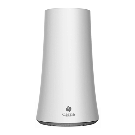
WEG Drive Scan User manual

Motors | Automation | Energy | Transmission & Distribution | Coatings
Drive Scan
Drive Specialist
Low Voltage Devices
Manual


Manual
Series: Low Voltage Devices
Language: English
Document Number: 10009054128 / 00
Build 00
Products:
Publication Date: 10/2021

Summary of reviews
Version Revision Description
1.0X 00 First edition.

Contents
Contents
1 INTRODUCTION .......................................................................1-1
1.1 ABBREVIATIONS AND DEFINITIONS ........................................................................... 1-1
1.2 OVERVIEW - DRIVE SCAN AND DRIVE SPECIALIST ...................................................... 1-2
2 INSTALLATION RECOMMENDATIONS.........................................2-0
2.1 INSPECTION ON RECEIPT ......................................................................................... 2-0
2.2 PHYSICAL INSTALLATION.......................................................................................... 2-0
3 WEG MOTION FLEET MANAGEMENT .........................................3-1
3.1 FUNCTIONALITIES AND DOCUMENTATION ................................................................. 3-1
3.2 REGISTERING AN ASSET........................................................................................... 3-1
4 DRIVE SCAN COMMUNICATION.................................................4-1
4.1 COMPATIBILITIES ..................................................................................................... 4-1
4.2 COMMUNICATION INTERFACES AND PROTOCOLS...................................................... 4-1
4.3 RS-485 CONNECTOR ................................................................................................ 4-2
4.4 NETWORK SETTINGS................................................................................................ 4-2
4.5 NUMBER OF MONITORED ASSETS............................................................................. 4-2
4.6 INTERNET CONNECTION REQUIREMENTS ................................................................. 4-2
5 CONNECTING A DEVICE TO THE DRIVE SCAN ............................5-1
5.1 RECOMMENDATIONS FOR CONNECTION VIA RS-485 .................................................. 5-1
5.2 CFW11 FREQUENCY INVERTER ................................................................................. 5-2
5.2.1 RS-485 ........................................................................................................... 5-2
5.2.2 ETHERNET ..................................................................................................... 5-3
5.2.3 POSSIBLE FORMS OF CONNECTIONS .............................................................. 5-5
5.2.4 MONITORING ................................................................................................. 5-6
5.3 CFW100 FREQUENCY INVERTER................................................................................ 5-8
5.3.1 RS-485 ........................................................................................................... 5-8
5.3.2 POSSIBLE FORMS OF CONNECTIONS .............................................................. 5-8
5.3.3 MONITORING ................................................................................................. 5-9
5.4 CFW300 FREQUENCY INVERTER.............................................................................. 5-11
5.4.1 RS-485 ......................................................................................................... 5-11
5.4.2 ETHERNET ................................................................................................... 5-11
5.4.3 POSSIBLE FORMS OF CONNECTIONS ............................................................ 5-12
5.4.4 MONITORING ............................................................................................... 5-13
5.5 INVERSOR DE FREQUÊNCIA CFW500 ....................................................................... 5-15
5.5.1 RS-485 ......................................................................................................... 5-15
5.5.2 ETHERNET ................................................................................................... 5-16
5.5.3 POSSIBLE FORMS OF CONNECTIONS ............................................................ 5-17
5.5.4 MONITORING ............................................................................................... 5-18
5.6 SOFT-STARTER SSW900 .......................................................................................... 5-20

Contents
5.6.1 RS-485 ......................................................................................................... 5-20
5.6.2 ETHERNET ................................................................................................... 5-20
5.6.3 POSSIBLE FORMS OF CONNECTIONS ............................................................ 5-21
5.6.4 MONITORING ............................................................................................... 5-22
5.7 SRW01 SMART RELAY............................................................................................. 5-24
5.7.1 ETHERNET ................................................................................................... 5-24
5.7.2 POSSIBLE FORMS OF CONNECTIONS ............................................................ 5-25
5.7.3 MONITORING ............................................................................................... 5-25
6 SETTING THE DRIVE SCAN ON THE MFM ...................................6-1
7 MONITORING DASHBOARD ......................................................7-1
7.1 ACCESS................................................................................................................... 7-1
7.2 FEATURES ............................................................................................................... 7-1
7.3 PARAMETERS .......................................................................................................... 7-1
8 DRIVE SPECIALIST ...................................................................8-1
8.1 COMPATIBILITY ........................................................................................................ 8-1
8.2 CFW11 FREQUENCY INVERTER ................................................................................. 8-1
8.2.1 Consumption .................................................................................................. 8-1
8.2.2 Diagnostic ...................................................................................................... 8-3
ASETTING THE IP ON WINDOWS 10 .......................................... A-0
Low Voltage Devices | 0-6

1
INTRODUCTION
1 INTRODUCTION
This document covers the general concepts and configurations of Drive Scan and Motion Fleet Management for
communication and monitoring of the WEG low voltage inverter line.
To complement the information contained in this document, please also refer to the contents related to the following
documents>
Manuals of the frequency inverters connected to the Drive Scan;
Manuals of the CFW11, CFW100, CFW300 and CFW500, SRW01 and SSW900 devices;
Manual of the WEG Motion Fleet Management platform.
All those manuals are available for download at the WEG website download center (www.weg.net).
Some procedures described are subject to changes that will not affect the user’s understanding.
1.1 ABBREVIATIONS AND DEFINITIONS
MFM WEG Motion Fleet Managment. Cloud service platform used in WEG IoT applications.
Drive Frequency inverter.
Asset Dispositivo que normalmente possui um bom valor agregado (um inversor de frequência
CFW11, por exemplo).
Attribute An attribute usually consists of only one variable monitored by the Drive Scan published in
the MFM, but there are situations where a variable is subdivided into more than one attribute,
such as: last value, average value, minimum value and maximum value.
DHCP Dynamic Host Configuration Protocol. Protocol that allows devices newly connected to a
network to obtain an IP address automatically.
DNS System responsible for translating IP addresses into domain names and vice versa.
Ethernet Interconnection architecture for local area networks (IEEE 802.3).
Firmware Set of operating instructions that are programmed directly into electronic equipment hard-
ware.
Gateway Electronic device that allows data flow between different communication networks.
Hardware Equipment or device.
IoT Internet of Things. Technology that allows machine-to-machine communication using an
internet connection.
IP Internet Protocol. Internet protocol for forwarding datagrams between networked devices.
Login Action for the user to access the system. It is usually necessary to enter a username and
password.
Logout Action that terminates the user’s connection to the system.
MQTT Message Queuing Telemetry Transport. Transport protocol that uses the publish/subscribe
architecture to transfer lightweight messages between devices.
Pop-up Window smaller than a screen, which is over the main window.
Plant Factory installation.
RS-485 Interface standard for asynchronous serial communication.
Site Set of plants.
Low Voltage Devices | 1-1

1
INTRODUCTION
Software A program or set of instructions executed by a microcontroller or a microprocessor.
URL Uniform Resource Locator. Web address of a resource available on a network.
Web World Wide Web. Hypertextual system that operates over the internet.
WLAN Wireless Local Area Network.
1.2 OVERVIEW - DRIVE SCAN AND DRIVE SPECIALIST
The Drive Scan consists of the WCD-ED300 gateway and the WEG Motion Fleet Management platform. It is
designed to monitor information of different assets and assist in their maintenance.
The Drive Scan has dedicated firmware to integrate assets with the MFM platform, performing several important
tasks, such as:
Registration on the MFM platform;
Reading of each connected asset;
Processing of the read data;
Data storage for up to 30 days in case of disconnection from the MFM;
Publishing of sampled data on the MFM platform.
It has smart code WCD-ED300-DSLV-2P2SE-W-POE, item 15474014.
The Drive Specialist (Chapter 8) adds to the Drive Scan advanced diagnostic features and information about the
CFW11 energy consumption.
Low Voltage Devices | 1-2

2
INSTALLATION RECOMMENDATIONS
2 INSTALLATION RECOMMENDATIONS
This manual contains the necessary information for the correct installation, configuration and use of the Drive Scan.
The document was developed for professionals with suitable training or technical qualifications to operate this type
of product. Failure to comply with the product instructions may cause operating accidents and damages to the
device, in addition to voiding the warranty. The user is responsible for the correct definition of the environment and
application characteristics.
2.1 INSPECTION ON RECEIPT
When you receive the Drive Scan, please check that the package contains the items listed below. Figure Figure 2.1
shows the accessories contained in the package.
1x WCD Drive Scan,
2x WiFi antenna,
1x power supply 12V + 2x socket plug.
1x Drive Scan 1x 12VDC power supply 2x WiFi antenna
2x Socket plug
Figure 2.1: Drive Scan and Accessories
2.2 PHYSICAL INSTALLATION
Installing the Drive Scan is a simple task. Just follow the steps listed below.
1. Insert both antennas, one into each input.
2. Insert one of the power plugs (at your discretion) into the power supply and insert the cable into the Drive
Scan power input.
3. Panel Installation:
a) Place the Drive Scan on the base of the panel and energize it through an outlet.
b) Or, if possible, snap the Drive Scan onto the DIN rail on the panel.
Low Voltage Devices | 2-0

2
INSTALLATION RECOMMENDATIONS
Or
(1) (2)
Drive
(3a) (3b)
Drive
12V
110-220V
50-60Hz
110-220V
50-60Hz
Figure 2.2: Instructions for the Drive Scan Physical Installation
WARNING!
Be sure to power the Drive Scan within 110V to 220V power range (with frequency from 50 to 60Hz).
Installation and configuration of the Drive Scan communication with WEG devices, as well as the platform config-
urations, are covered in the following chapters.
Low Voltage Devices | 2-1

2
INSTALLATION RECOMMENDATIONS
Low Voltage Devices | 2-2

3
WEG MOTION FLEET MANAGEMENT
3 WEG MOTION FLEET MANAGEMENT
3.1 FUNCTIONALITIES AND DOCUMENTATION
The WEG Motion Fleet Management platform is WEG’s IoT system that performs the user’s interaction in a secure
environment. Among other things, the platform main functions are:
Account and user management;
Plant and site edition;
Subscription request;
Asset registration;
Presentation of each asset in dashboards;
Presentation of performance indicators;
Maintenance management;
Complete health diagnostics of the asset (only with the Drive Specialist subscription for the CFW-11 frequency
inverter);
Estimation and prediction of variables through the Drive Specialist.
Access the WEG Motion Fleet management at https://mfm.wnology.io, fill out your registration and download the
MFM guide. To that end, just select the ”Guide” option from the ”User” menu, located on the upper right corner of
the page, as shown in Figure 3.1.
Figure 3.1: Access to the MFM manual
While reading the MFM guide, take the opportunity to organize the site and the plans. After that, you can register
your assets on the platform. This will simplify the initial configuration of the Drive Scan, which will be detailed in
Chapter 6.
3.2 REGISTERING AN ASSET
Before registering an asset, it is necessary to register the Drive Scan on the WEG Motion Fleet Management
platform, as explained in Chapter 6.
Low Voltage Devices | 3-1

3
WEG MOTION FLEET MANAGEMENT
Step 1 In the web browser, access the website https://mfm.wnology.io.
Enter your email and password and click on the “SIGN IN” button, as shown in Figure 3.2.
If you don’t have an account, create one through the “Sign up” link.
Figure 3.2: Accessing the WEG MFM platform
Low Voltage Devices | 3-2

3
WEG MOTION FLEET MANAGEMENT
Step 2 Click on the menu and select the “REGISTER AND UPDATE” option.
Click on the ”Device” option, as shown in Figure 3.3.
Figure 3.3: Registering a new device
Step 3 Click on ”+DEVICE” button, as shown in Figure 3.4.
Figure 3.4: Adding a device
Step 4 Select the ”Drive” option and click on the ”Register” button, as shown in Figure 3.5.
Figure 3.5: Adding a drive
Low Voltage Devices | 3-3

3
WEG MOTION FLEET MANAGEMENT
Step 5 WARNING!
The Drive Scan must have been previously registered on the MFM, as described in
Chapter 6.
Select Drive Scan and click on the ”CONTINUE” button, as shown in Figure 3.6.
Figure 3.6: Ading a drive
Step 6 Click on the ”+ADD” button, as shown in Figure 3.7.
Figure 3.7: Adding a drive to the MFM
Low Voltage Devices | 3-4

3
WEG MOTION FLEET MANAGEMENT
Step 7 Enter your device name.
Select your device connection mode to Drive Scan.
In Figure 3.8, the RS-485 option was chosen. The following settings are related to this choice.
Figure 3.8: Registering a drive
Set the drive ModBus address.
Select the device model (asset).
Enter the asset serial number.
Click on the “SAVE” button.
Step 8 Click on the name of your asset to view the dashboard, as shown in Figure 3.9.
Figure 3.9: List of registered drives in the Drive Scan on the MFM
Low Voltage Devices | 3-5

4
DRIVE SCAN COMMUNICATION
4 DRIVE SCAN COMMUNICATION
4.1 COMPATIBILITIES
To establish communication between the Drive Scan and the inverter, make sure that each system has a suitable
version. Table 4.1 contains the version compatibilities of the Drive Scan system components.
Table 4.1: Version compatibility for the Drive Scan communication
v0.0.1 v0.0.5 v0.0.8 v0.1.x v0.3.x v0.4.x v0.5.x v1.x.x
Scan Application xxxxxxx
v1.0.0 v1.1.0 v1.2.0 v1.3.0 v1.4.0 v1.5.0 v1.6.0 v1.7.0 v1.8.x v1.9.x
WCD ED300 DSLV xxxxxxx
v1.00 v1.10 v1.17 v1.18 v1.19 v1.2x v1.6.0 v1.7.0 v1.8.x v1.9.x
Wnology/Edge-Agent xxxxxxxx
v1.0.xx v1.1.xx v1.2.xx v1.3.xx v1.4.xx v1.5.xx v1.6.0x v1.7.0xx v1.8.xx v1.9.xx
Motion Fleet
Management xxxxxxxxx
The compatibility of each product with the Drive Scan can be seen in their respective sections, in Chapter 5.
4.2 COMMUNICATION INTERFACES AND PROTOCOLS
The WCD-ED300 Drive Scan connects to the assets by one of the following communication interfaces, according
to Figure 4.1:
Ethernet port GbE1 (1), using Modbus-TCP protocol;
RS-485 port (2), using Modbus-RTU protocol.
Figure 4.1: WCD-ED300 Drive Scan Communication Interfaces
Low Voltage Devices | 4-1

4
DRIVE SCAN COMMUNICATION
4.3 RS-485 CONNECTOR
Table 4.2: Signals of the WCD-ED300 Drive Scan RS-485 Connector
Pino Sinal
1Negative RS-485
2GND
3Positive RS-485
4Positive RS-485
5GND
6Negative RS-485
4.4 NETWORK SETTINGS
All the devices connected to physical networks, whether via RS-485 or Ethernet, must have the same baud rate,
data bit, parity and stop bit settings, so that the respective network works correctly.
4.5 NUMBER OF MONITORED ASSETS
The Drive Scan WCD-ED300 allows connecting and monitoring up to 10 assets on the RS-485 network and up
to 10 assets on the Ethernet network, for a maximum of 20 assets. Chapter 5 describes the settings and possible
ways of connecting the low voltage frequency inverters to the Drive Sca.
In the case of the SRW01, the WCD-ED300 Drive Scan allows connecting and monitoring up to 20 relays on the
Ethernet network . Note: It is only possible to monitor the SRW01 on Ethernet models. Chapter 5.7 describes the
settings and possible ways of connecting the relay to the Drive Scan.
4.6 INTERNET CONNECTION REQUIREMENTS
For the proper operation of the Drive Scan and connection to the MFM cloud, the customer’s network must meet
some requirements and have some releases.
Note: to release the addresses, ports and internet access, ask the IT team in charge of the network.
The user’s network must not have VPN or PROXY;
The ports of Table 4.3 and the IP addresses of Table 4.4 must be accessible.
Table 4.3: Addresses required for the Drive Scan communication with the MFM
Destino IP Objective
broker.app.wnology.io 146.0.0.0/8 Send data to the MFM
hub.docker.com 3.225.66.59 Edge-Agent Maintenance
nexus3.weg.net Dynamic address Firmware update
Table 4.4: Ports required for the Drive Scan communication with the MFM
Protocolo Porta Objetivo
TCP 80 Update/Support the Drive Scan
and Send data to the MFM
TCP 433
TCP 1883
TCP 8883
Low Voltage Devices | 4-2

5
CONNECTING A DEVICE TO THE DRIVE SCAN
5 CONNECTING A DEVICE TO THE DRIVE SCAN
5.1 RECOMMENDATIONS FOR CONNECTION VIA RS-485
When connecting the Drive Scan to any WEG device via serial (RS-485), terminations must be provided at the
external connection points. In cases where both ends are arranged on the CFW, SSW or MVW lines, their interfaces
already have switches to enable the termination resistors. Figure 5.1 illustrates the situation.
SSW
MVW
CFW
Drive Scan
...
Termination Termination
ModBus RTU network
Figure 5.1: ModBus RTU network with WEG devices at the ends
In case the ED300 is at an end, it is recommended to use an external termination module, such as those listed
below:
PSB-TERMINATOR-PB-TBUS (Phoenix Contact);
6ES7972-6DA00-0AA0 (Siemens);
AT303 (Smar)
Figure 5.2 illustrates the situation.
SSW
MVW
CFW
Drive Scan
...
ModBus RTU network
Termination
module
Termination
Figure 5.2: ModBus RTU network with Drive Scan at one end
Low Voltage Devices | 5-1
Other manuals for Drive Scan
1
This manual suits for next models
1
Table of contents
Other WEG Gateway manuals