netvox R718B1 Series User manual

Wireless Temperature Sensor
R718B1 Series
Wireless Temperature Sensor
R718B1 Series
User Manual
Copyright©Netvox Technology Co., Ltd.
This document contains proprietary technical information which is the property of NETVOX Technology. It shall be maintained
in strict confidence and shall not be disclosed to other parties, in whole or in part, without written permission of NETVOX
Technology. The specifications are subject to change without prior notice.

1
Table of Content
1. Introduction.............................................................................................................................................................2
2. Appearance..............................................................................................................................................................2
3. Main Features..........................................................................................................................................................3
4. Set up Instruction ....................................................................................................................................................4
5. Data Report .............................................................................................................................................................5
5.1 Example of ReportDataCmd............................................................................................................................5
5.2 Example of Report configuration ....................................................................................................................7
5.3 Example for MinTime/MaxTime logic............................................................................................................8
6. Installation...............................................................................................................................................................9
7. Information about Battery Passivation .................................................................................................................10
7.1 To determine whether a battery requires activation ......................................................................................10
7.2 How to activate the battery............................................................................................................................10
8. Relevant Products..................................................................................................................................................11
9. Important Maintenance Instruction.......................................................................................................................11

2
R718B140 R718B141
Round head probe Needle probe
1.Introduction
The R718B1 series is a Wireless Resistance Temperature Detector for Netvox ClassAtype devices based on the LoRaWAN
open protocol and is compatible with the LoRaWAN protocol.
R718Bconnects an external resistance temperature detector (PT1000) to measures the temperature.
LoRa Wireless Technology:
LoRa is a wireless communication technology dedicated to long distance and low power consumption. Compared with other
communication methods, LoRa spread spectrum modulation method greatly increases to expand the communication distance.
Widely used in long-distance, low-data wireless communications. For example, automatic meter reading, building automation
equipment, wireless security systems, industrial monitoring. Main features include small size, low power consumption,
transmission distance, anti-interference ability and so on.
LoRaWAN:
LoRaWAN uses LoRa technology to define end-to-end standard specifications to ensure interoperability between devices and
gateways from different manufacturers.
2.Appearance
Indicator
Function Key
R718B120 R718B121
Round head probe Needle probe

3
R718B250R718B251
Absorption probe
R718B122
3. Main Features
Adopt SX1276 LoRa wireless communication module.
PT1000 Platinum resistance temperature sensor detection
Main body IP rating: IP65/IP67 (optional)
R718B120, R718B121 temperature range: -70°C to 200°C, Sensor IP rating: IP67
R718B122 temperature range: -50°C to 180°C, Sensor IP rating: IP67
R718B140, R718B141 temperature range: -40°C to 375°C, Sensor IP rating: IP50
R718B150, R718B151 temperature range: -40°C to 500°C, Sensor IP rating: IP50
2 x ER14505 lithium batteries in parallel.
The base is attached with a magnet that can be attached to a ferromagnetic material object
Compatible with LoRaWANTM Class A
Frequency hopping spread spectrum
Applicable to third-party platforms: Actility/ThingPark, TTN, MyDevices/Cayenne
Low power consumption and long battery life
Battery Life:
⁻Please refer to web: http://www.netvox.com.tw/electric/electric_calc.html
⁻At this website, users can find battery life time for variety models at different configurations.
Round head probe Needle probe

4
4. Set up Instruction
On/Off
Power on Insert batteries. (Users may need a screwdriver to open)
Turn on Press and hold the function key for 3 seconds till the green indicator flashes once.
Turn off (Restore to factory setting) Press and hold the function key for 5 seconds till green indicator flashes for 20 times.
Power off Remove Batteries.
Note
1. Remove and insert the battery; the device is at off state by default.
2. On/off interval is suggested to be about 10 seconds to avoid the interference of
capacitor inductance and other energy storage components.
3. At 1st -5th second after power on, the device will be in engineering test mode.
Network Joining
Never joined the network
Turn on the device to search the network to join.
The green indicator stays on for 5 seconds: success
The green indicator remains off: fail
Had joined the network
(not at factory setting)
Turn on the device to search the previous network to join.
The green indicator stays on for 5 seconds: success
The green indicator remains off: fail
Function Key
Press and hold for 5 seconds
Restore to factory setting / Turn off
The green indicator flashes for 20 times: success
The green indicator remains off: fail
Press once The device is in the network: green indicator flashes once and sends a report
The device is not in the network: green indicator remains off
Sleeping Mode
The device is on and in the network
Sleeping period: Min Interval.
When the reportchange exceeds setting value or the state changes: send a data report
according to Min Interval.
Low Voltage Warning
Low Voltage 3.2V
*Suggest to remove batteries if the device is not used.

5
5. Data Report
Data report configuration and sending period are as following:
5.1 Example of ReportDataCmd
FPort:0x06
Bytes 1 1 1 Var(Fix=8 Bytes)
Version DeviceType ReportType NetvoxPayLoadData
Version– 1 byte –0x01——the Version of NetvoxLoRaWAN Application Command Version
DeviceType– 1 byte – Device Type of Device
The devicetype is listed in Netvox LoRaWAN Application Devicetype doc
ReportType – 1 byte –the presentation of the NetvoxPayLoadData,according the devicetype
NetvoxPayLoadData– Fixed bytes (Fixed =8bytes)
Min Interval
(Unit:second)
Max Interval
(Unit:second) Reportable Change Current Change≥
Reportable Change
Current Change<
Reportable Change
Any number between
1~65535
Any number between
1~65535 Can not be 0. Report
per Min Interval
Report
per Max Interval
The device will immediately send a version packet report along with an uplink packet including temperature and battery
voltage.
The device sends data in the default configuration before any configuration is done.
Default setting:
Max Interval: 0x0384 (900s)
Min Interval: 0x0384 (900s)
BatteryChange: 0x01 (0.1V)
TemperatureChange:0x0064 (10°C)
Note:
The device report interval will be programmed based on the default firmware which may vary.
The interval between two reports must be the minimum time.
Please refer Netvox LoRaWAN Application Command document and Netvox Lora Command Resolver
http://cmddoc.netvoxcloud.com/cmddoc to resolve uplink data.

6
Device Device
Type
Report
Type NetvoxPayLoadData
R718B1 series 0x95
0x00 SoftwareVersion
(1Byte) Eg.0x0A—V1.0
HardwareVersion
(1Byte)
DateCode
(4Bytes,eg0x20170503)
Reserved
(2Bytes,fixed 0x00)
0x01 Battery
(1Byte, unit:0.1V)
Temperature
(Signed2Bytes,unit:0.1°C)
Reserved
(5Bytes,fixed 0x00)
Example 1 of Uplink: 0195012401090000000000
1st byte (01): Version
2nd byte (95): DeviceType 0x95-R718B1 series
3rd byte (01): ReportType
4th byte (24): Battery-3.6V, 24(Hex) = 36(Dec), 36x0.1v=3.6v
5th6th byte (0109): Temperature-26.5 oC , 109(Hex)=265(Dec), 265x0.1°C=26.5°C
7th-11th byte (00000000000): Reserved
Example 2 of Uplink: 019501A0FF390000000000
1st byte (01): Version
2ndbyte (95): DeviceType 0x95-R718B1 series
3rd byte (01): ReportType
4th byte (A0): Battery-3.2V (Low battery), 20(Hex) = 32(Dec), 32x0.1v=3.2v //The bit7 is 1,represent low battery
5th6th byte (FF39): Temperature--19.9oC , 0x10000-0xFF39=0xC7(Hex), 0xC7(Hex)=199(Dec) , -199x0.1°C= -19.9°C
7th-11th byte (0000000000): Reserved
Tips
1. Battery Voltage:
The voltage value is bit 0 ~ bit 6, bit 7=0 is normal voltage, and bit 7=1 is low voltage.
Battery=0xA0, binary=1010 0000, if bit 7= 1, it means low voltage.
The actual voltage is 0010 0000 = 0x20 = 32, 32*0.1v =3.2v
2. Version Packet:
When Report Type=0x00 is the version packet, such as 0195000A0B202005200000, the firmware version is 2020.05.20
3. Data Packet:
When Report Type=0x01 is data packet.
4. Signed Value:
When the temperature is negative, 2's complement should be calculated.

7
5.2 Example of Report configuration
FPort:0x07
Bytes 1 1 Var(Fix =9 Bytes)
CmdID DeviceType NetvoxPayLoadData
CmdID– 1 byte
DeviceType– 1 byte – Device Type of Device
NetvoxPayLoadData– var bytes (Max=9bytes)
(1) Configure device parameters MinTime = 1min, MaxTime = 1min, BatteryChange = 0.1v, Temperaturechange = 10°C
Downlink: 0195003C003C0100640000
Devices return:
8195000000000000000000 (configuration is successful)
8195010000000000000000 (configuration is failed)
(2) Read device parameters
Downlink: 0295000000000000000000
Devices return:
8295003C003C0100640000 (current device configuration parameters)
Description Device Cmd
ID
Device
Type NetvoxPayLoadData
Config
ReportReq
R718B1
series
0x01
0x95
MinTime
(2bytes Unit:s)
MaxTime
(2bytes Unit:s)
BatteryChange
(1byte Unit:0.1v)
Temperaturechange
(2byte Unit:0.1°C)
Reserved
(2Bytes,Fixed 0x00)
Config
ReportRsp 0x81 Status
(0x00_success)
Reserved
(8Bytes,Fixed 0x00)
ReadConfig
ReportReq 0x02 Reserved
(9Bytes,Fixed 0x00)
ReadConfig
ReportRsp 0x82 MinTime
(2bytes Unit:s)
MaxTime
(2bytes Unit:s)
BatteryChange
(1byte Unit:0.1v)
Temperaturechange
(2byte Unit:0.1°C)
Reserved
(2Bytes,Fixed 0x00)

8
5.3 Example for MinTime/MaxTime logic
Example#1 based on MinTime = 1 Hour, MaxTime= 1 Hour, Reportable Change i.e. BatteryVoltageChange=0.1V
MaxTime MaxTime
Sleeping(MinTime) Sleeping(MinTime)
Note: MaxTime=MinTime. Data will only be report according to MaxTime (MinTime) duration regardless BatteryVoltageChange
value.
Example#2 based on MinTime = 15 Minutes, MaxTime= 1 Hour, Reportable Change i.e. BatteryVoltageChange= 0.1V.
MaxTime
Sleeping(MinTime) sleeping sleeping sleeping
0H 15th M 30th M 45th M 1H 2H
Example#3 based on MinTime = 15 Minutes, MaxTime= 1 Hour, Reportable Change i.e. BatteryVoltageChange= 0.1V.
MaxTime
sleeping sleeping ...
0H 15th M 30th M 45th M 1H 1H 10th M 1H 25th M 1H 40th M 1H 55th M 2H 10th M
Notes :
Wakes up and
collects data
3.6V
Does not report
Wakes up and
collects data
3.6V
Does not report
Wakes up and
collects data
3.6V
Does not report
Wakes up and
collects data
REPORTS 3.6V
Wakes up and
collects data
REPORT 3.6V
Wakes up and
collects data
REPORTS 3.6V
Wakes up and collects data
3.5V |3.5-3.6|=0.1
REPORTS 3.5V
Wakes up and
collects data
3.5V
Does not report
Wakes up and
collects data
3.5V
Does not report
Wakes up and
collects data
3.5V
Does not report
Wakes up and
collects data 3.5V
Does not report
Wakes up and
collects data
3.5V
Does not report
Wakes up and
collects data
REPORTS 3.5V
Wake up and collects data
REPORTS 3.6V
Wakes up and collects data
REPORTS 3.6V
Wakes up and collects data
REPORTS 3.6V
Wakes up and
collects data
3.6V
Does not report
Users push the button,
REPORTS 3.5V.
Recalculate MaxTime.
9
1) The device only wakes up and performs data sampling according to MinTime Interval. When it is sleeping, it does not
collect data.
2) The data collected is compared with the last data reported. If the data variation is greater than the ReportableChange
value, the device reports according to MinTime interval. If the data variation is not greater than the last data reported, the
device reports according to MaxTime interval.
3) We do not recommend to set the MinTime Interval value too low. If the MinTime Interval is too low, the device wakes up
frequently and the battery will be drained soon.
4) Whenever the device sends a report, no matter resulting from data variation, button pushed or MaxTime interval, another
cycle of MinTime/MaxTime calculation is started.
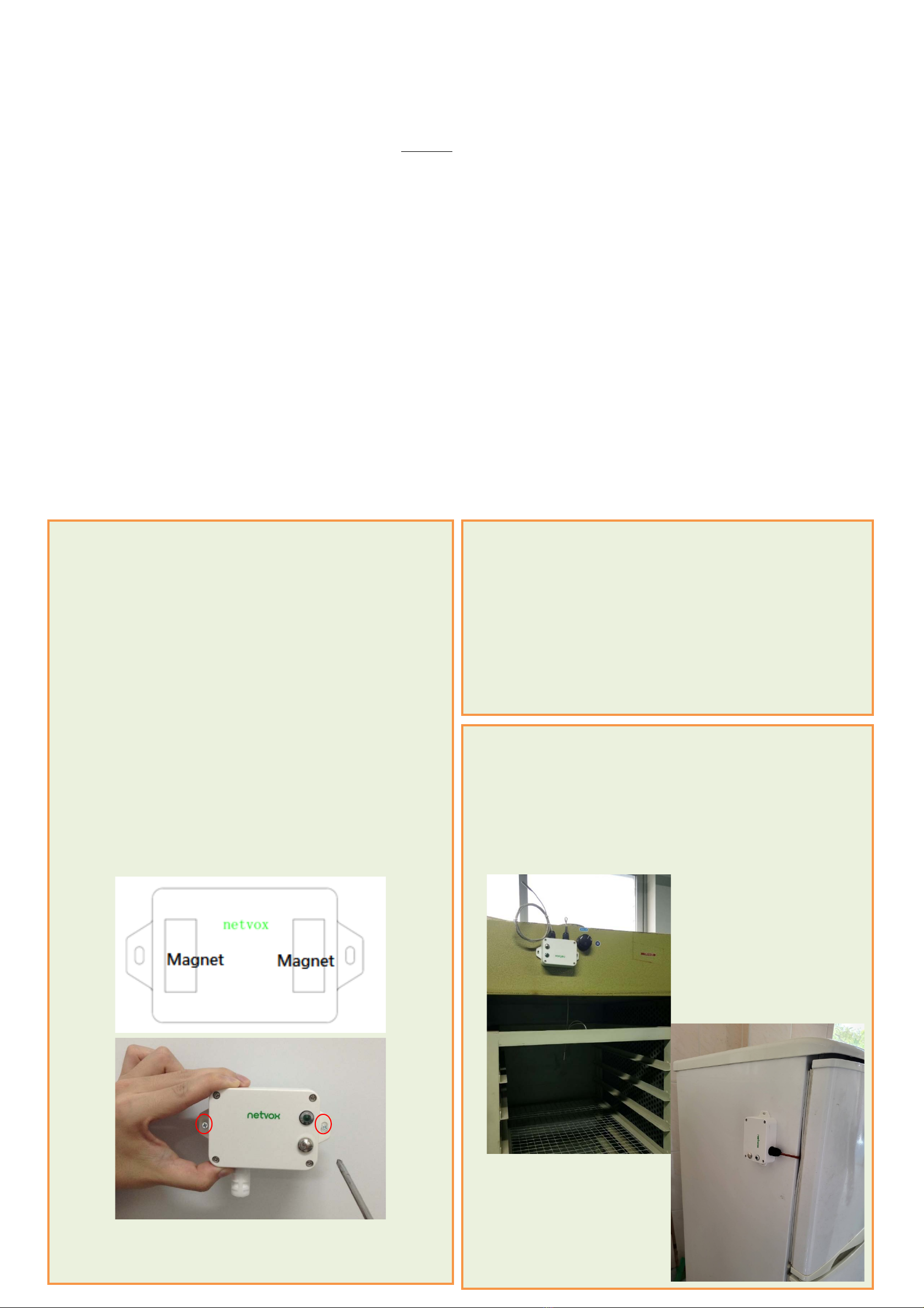
6. Installation
This product comes with waterproof function.
When using it, the back of it can be adsorbed on the iron surface, or the two ends can be fixed to the wall with screws.
1. The Wireless Resistance Temperature Detector (R718B) has
a built-in magnet (see Figure 1 below). When installed, it can
be attached to the surface of an object with iron which is
convenient and quick.
To make the installation more secure, use screws (purchased)
to secure the unit to a wall or other surface (see below).
Note:
Do not install the device in a metal shielded box or in an
environment with other electrical equipment around it to
avoid affecting the wireless transmission of the device.
Screw hole diameter: Ø4mm
R718B is suitable below scenarios:
Oven
Industrial control equipment
Semiconductor industry
2. When R718B is compared with the last reported values, the
temperature change is exceeded 0.1°C (default),it will report
values at the MinTime interval;
If does not exceeded 0.1°C (default) ,it will report values at the
MaxTime interval;

10
Note:
Please do not disassemble the device unless it is required to replace the batteries.
Do not touch the waterproof gasket, LED indicator light, function keys when replacing the batteries. Please use suitable
screwdriver to tighten the screws (if using an electric screwdriver, it is recommended to set the torque as 4kgf) to ensure the
device is impermeable.
7. Information about Battery Passivation
Many of Netvox devices are powered by 3.6V ER14505 Li-SOCl2 (lithium-thionyl chloride) batteries that offer many
advantages including low self-discharge rate and high energy density.
However, primary lithium batteries like Li-SOCl2 batteries will form a passivation layer as a reaction between the lithium
anode and thionyl chloride if they are in storage for a long time or if the storage temperature is too high. This lithium chloride
layer prevents rapid self-discharge caused by continuous reaction between lithium and thionyl chloride, but battery passivation
may also lead to voltage delay when the batteries are put into operation, and our devices may not work correctly in this situation.
As a result, please make sure to source batteries from reliable vendors, and it is suggested that if the storage period is more
than one month from the date of battery production, all the batteries should be activated.
If encountering the situation of battery passivation, users can activate the battery to eliminate the battery hysteresis.
ER14505 Battery Passivation:
7.1 To determine whether a battery requires activation
Connect a new ER14505 battery to a resistor in parallel, and check the voltage of the circuit.
If the voltage is below 3.3V, it means the battery requires activation.
7.2 How to activate the battery
a. Connect a battery to a resistor in parallel
b. Keep the connection for 5~8 minutes
c. The voltage of the circuit should be ≧3.3, indicating successful activation.
Brand Load Resistance Activation Time Activation Current
NHTONE 165 Ω 5 minutes 20mA
RAMWAY 67 Ω 8 minutes 50mA
EVE 67 Ω 8 minutes 50mA
SAFT 67 Ω 8 minutes 50mA
Note:
If you buy batteries from other than the above four manufacturers, then the battery activation time, activation current, and
required load resistance shall be mainly subject to the announcement of each manufacturer.

11
8. Relevant Products
Model
Temperature
Range
Wire
Material
Wire
Length
Probe
Type
Probe
Material
Probe
Dimension
Probe
IP Rating
R718B120 One-gang
-70° to 200°C
PTFE
+
silicone
2m
Round head
316 stainless steel
Ø5mm*30mm
IP67
R718B220 Two-gang
R718B121 One-gang Needle Ø5mm*150mm
R718B221 Two-gang
R718B122 One-gang -50° to 180°C
Absorption NdFeB magnet +
stainless steel spring
Ø15mm
R718B222 Two-gang
R718B140 One-gang
-40° to 375°C
Braided
Fiberglass
Round head
316 stainless steel
Ø5mm*30mm
IP50
R718B240 Two-gang
R718B141 One-gang Needle Ø5mm*150mm
R718B241 Two-gang
R718B150 One-gang
-40° to 500°C
Round head Ø5mm*30mm
R718B250 Two-gang
R718B151 One-gang Needle Ø5mm*150mm
R718B251 Two-gang
9. Important Maintenance Instruction
Kindly pay attention to the following in order to achieve the best maintenance of the product:
•Keep the device dry. Rain, moisture, or any liquid, might contain minerals and thus corrode electronic circuits. If the device
gets wet, please dry it completely.
•Do not use or store the device in dusty or dirty environment. It might damage its detachable parts and electronic components.
•Do not store the device under excessive heat condition. High temperature can shorten the life of electronic devices, destroy
batteries, and deform or melt some plastic parts.
•Do not store the device in places that are too cold. Otherwise, when the temperature rises to normal temperature, moisture will
form inside, which will destroy the board.
•Do not throw, knock or shake the device. Rough handling of equipment can destroy internal circuit boards and delicate
structures.
•Do not clean the device with strong chemicals, detergents or strong detergents.
•Do not apply the device with paint. Smudges might block in the device and affect the operation.
•Do not throw the battery into the fire, or the battery will explode. Damaged batteries may also explode.
All of the above applies to your device, battery and accessories.
If any device is not working properly, please take it to the nearest authorized service facility for repair.
This manual suits for next models
7
Table of contents
Other netvox Accessories manuals

netvox
netvox R718N1 User manual

netvox
netvox R718DB User manual

netvox
netvox R718UBB Series User manual

netvox
netvox R313WA User manual

netvox
netvox ZigBee Z311G User manual

netvox
netvox R718PA5 User manual

netvox
netvox R718E User manual

netvox
netvox R72616A User manual

netvox
netvox R718EB User manual

netvox
netvox R72632A01 User manual

netvox
netvox R718N3 User manual

netvox
netvox R718VA User manual

netvox
netvox R718PA5 User manual

netvox
netvox Contact Sensor Series User manual

netvox
netvox R712 User manual

netvox
netvox R718AD User manual

netvox
netvox RA0701 User manual

netvox
netvox R311B User manual

netvox
netvox R718LB User manual

netvox
netvox R72615A User manual


