netvox R718EB User manual

R718EB
Wireless Tilt Angle Sensor
R718EB
User Manual
Copyright© Netvox Technology Co., Ltd.
This document contains proprietary technical information which is the property of NETVOX Technology. It shall be maintained
in strict confidence and shall not be disclosed to other parties, in whole or in part, without written permission of NETVOX
Technology. The specifications are subject to change without prior notice.
Wireless Tilt Angle Sensor

2
Table of Content
1. Introduction.............................................................................................................................................................3
2. Appearance..............................................................................................................................................................3
3. Main Features..........................................................................................................................................................4
4. Application ..............................................................................................................................................................4
5. Set up Instruction ....................................................................................................................................................5
6. Data Report .............................................................................................................................................................6
6.1 ActiveThreshold and InActiveThreshold ........................................................................................................7
6.2 Calibration........................................................................................................................................................7
6.3 Example of data configuration ........................................................................................................................7
6.4 Example for MinTime/MaxTime logic............................................................................................................9
7. Installation.............................................................................................................................................................10
8. Information about Battery Passivation .................................................................................................................11
8.1 To determine whether a battery requires activation ......................................................................................11
8.2 How to activate the battery............................................................................................................................11
9. Important Maintenance Instruction.......................................................................................................................12
3
1. Introduction
R718EB is the ClassA device based on the LoRaWANTM protocol of Netvox. The device detects the tilt angle of three axes.
When the device moves or shakes beyond the set threshold, and the angle variation of any one of the three axes is greater than the
set threshold, it will immediately report the current tilt angle of the X, Y, and Z axes and the battery voltage. The device is
compatible with LoRaWAN protocol.
LoRa Wireless Technology:
LoRa is a wireless communication technology dedicated to long distance and low power consumption. Compared with other
communication methods, LoRa spread spectrum modulation method greatly increases to expand the communication distance.
Widely used in long-distance, low-data wireless communications. For example, automatic meter reading, building automation
equipment, wireless security systems, industrial monitoring. Main features include small size, low power consumption,
transmission distance, anti-interference ability and so on.
LoRaWAN:
LoRaWAN uses LoRa technology to define end-to-end standard specifications to ensure interoperability between devices and
gateways from different manufacturers.
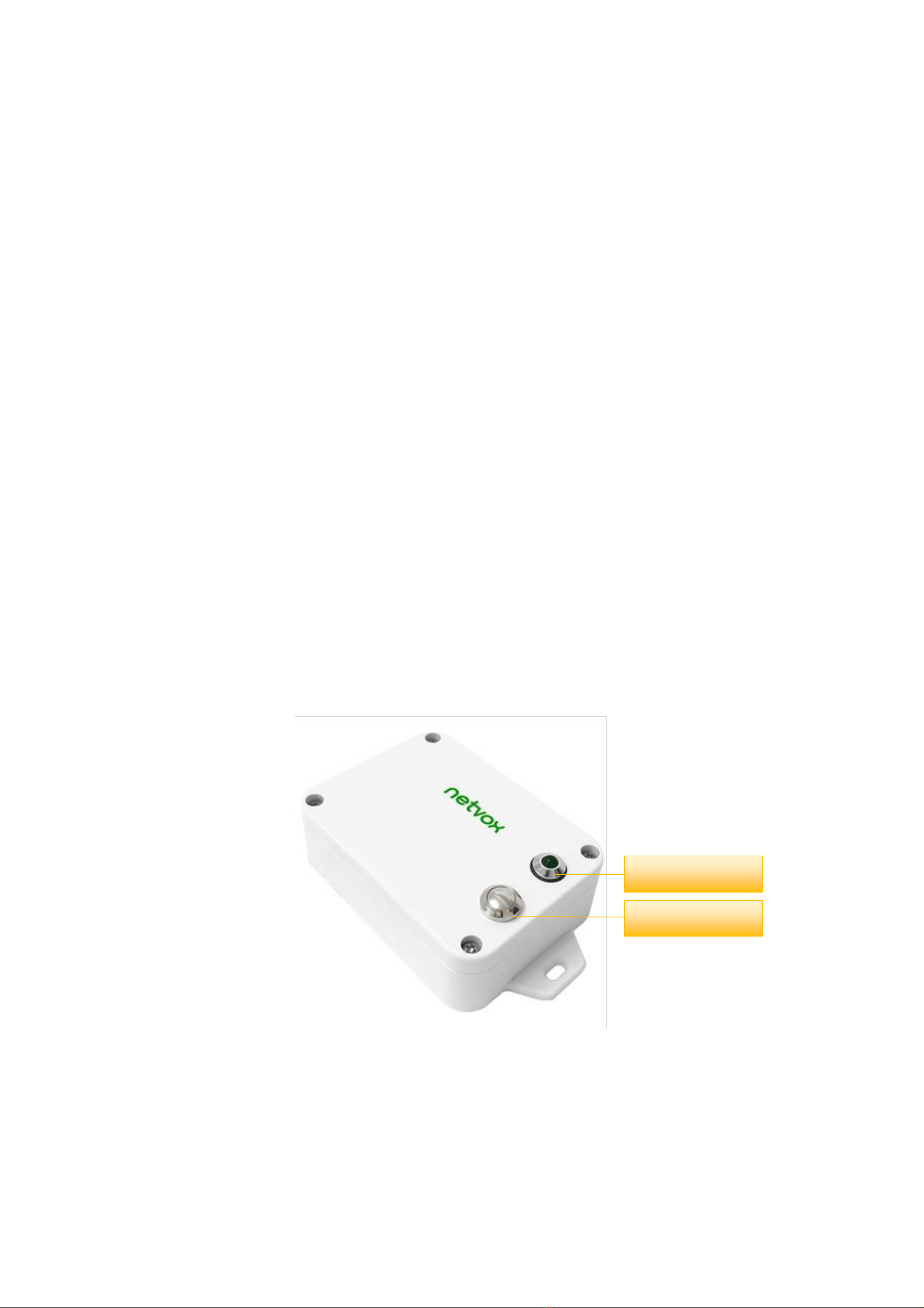
2. Appearance
Indicator
Function Key

4
3. Main Features
⚫Apply SX1276 wireless communication module
⚫2 sections ER14505 3.6V Lithium AA size battery in parallel
⚫Built-in tilt measurement chip
⚫The base is attached with a magnet that can be attached to a ferromagnetic material object
⚫Protection level IP65/IP67 (optional)
⚫Compatible with LoRaWANTM Class A
⚫Frequency hopping spread spectrum technology
⚫Configuration parameters can be configured through third-party software platforms, data can be read and alarms can be set via
SMS text and email (optional)
⚫Available third-party platform: Actility / ThingPark, TTN, MyDevices/Cayenne
⚫Low power consumption and long battery life
Battery Life:
⁻Please refer to web: http://www.netvox.com.tw/electric/electric_calc.html
⁻At this website, users can find battery life time for variety models at different configurations.
1. Actual range may vary depending on environment.
2. Battery life is determined by sensor reporting frequency and other variables.
4. Application
⚫Pillars, telegraph poles and other applications such as tilt sensing, angle detection, direction identification, etc.
⚫Industrial equipment
⚫Other

5
5. Set up Instruction
On/Off
Power on
Insert batteries. (users may need a screwdriver to open)
Turn on
Press and hold the function key for 3 seconds till the green indicator flashes once.
Turn off
(Restore to factory setting)
Press and hold the function key for 5 second, and the green indicator flashes 20 times.
Power off
Remove Batteries.
Note:
1. Remove and insert the battery; the device is at off state by default.
2. On/off interval is suggested to be about 10 seconds to avoid the interference of capacitor
inductance and other energy storage components.
3. The first 5 seconds after power on, the device will be in engineering test mode.
Network Joining
Never joined the network
Turn on the device to search the network.
The green indicator stays on for 5 seconds: success
The green indicator remains off: fail
Had joined the network
Turn on the device to search the previous network.
The green indicator stays on for 5 seconds: success
The green indicator remains off: fail
Function Key
Press and hold for 5 seconds
Restore to factory setting / Turn off
The green indicator flashes 20 times: success
The green indicator remains off: fail
Press once
The device is in the network: green indicator flashes once and sends a report
The device is not in the network: green indicator remains off
Sleeping Mode
The device is on and in the
network
Sleeping period: Min Interval.
When the reportchange exceeds setting value or the state changes: send a data report according to
Min Interval.
Low Voltage Warning
Low Voltage
3.2V

6
6. Data Report
The device will send a version package report immediately after power-on. After it is powered on, and the auto-calibration
is executed for one minute (Do not move the device), the device will report the attribute data.
Note:
1. The device must be placed horizontally during automatic calibration.
2. After calibration, the x, y, z three-axis angles are about 0°, 0°, -90°when the device is placed horizontally.
3. There will be no operation when pressing the button before the automatic calibration is completed.
The device sends data in the default configuration before any configuration is done.
Default setting:
MaxTime: Max Interval = 60 min = 3600s
MinTime: Max Interval = 60 min = 3600s (It is recommended that MinTime is not less than 1min.)
(By default, the current voltage and three-axis tilt value are detected once every Min Interval.)
Battery Change = 0x01 (0.1v)
Angle Change = 0xC8 (1°; The accuracy is 3°in horizontal position.)
Angle of Three-axis:
If the three-axis acceleration of the device exceeds ActiveThreshold, and the tilt angle variation of one of the three axes
is greater than or equal to the set AngleChange after the device is stationary, a report will be sent. After the three-axis tilt
angle and battery voltage are reported, the three-axis acceleration of the device needs to be lower than InActiveThreshold,
the duration is greater than 5s (cannot be modified), and the vibration stops completely, the next detection will start. If the
vibration continues during this process after the report is sent, the timing will restart.
Note:
(1) The device report interval will be programmed based on the default firmware which may vary.
(2) The interval between two reports must be the minimum time.
Please refer Netvox LoRaWAN Application Command document and Netvox Lora Command Resolver
http://loraresolver.netvoxcloud.com:8888/page/index to resolve uplink data.

7
Data report configuration and sending period are as following:
6.1 ActiveThreshold and InActiveThreshold
Formula
Active Threshold =Critical value ÷ 9.8÷ 0.0625
* The gravitational acceleration at standard atmospheric pressure is 9.8 m/s2
* The scale factor of the threshold is 62.5 mg
Active Threshold
Active Threshold can be changed by ConfigureCmd
Active Threshold range is 0x0003-0x00FF (default is 0x0003);
InActive Time
InActive Time can be changed by ConfigureCmd
InActive Time means that the acceleration variation during the stationary time is less than the set
InActive Threshold to declare stationary.
Example
Assuming that the critical value is set to 10m/s2, the Active Threshold (or InActive Threshold) to be set is
10/9.8/0.0625=16.32
Active Threshold (or InActiveThreshold) to be set integer as 16.
6.2 Calibration
The accelerometer is a mechanical structure that contains components that can move freely.
These moving parts are very sensitive to mechanical stress, far beyond solid-state electronics.
The 0g offset is an important accelerometer indicator because it defines the baseline used to measure acceleration.
After installing R718EB, users need to let the device rest for 1 minute, and then power on. Then, turn on the device and wait for
the device taking 1 minute to join the network. After that, the device will automatically executes the calibration.
6.3 Example of data configuration
FPort:0x07
Bytes
1
1
Var(Fix =9 Bytes)
CmdID
DeviceType
NetvoxPayLoadData
CmdID–1 byte
DeviceType–1 byte –Device Type of Device
NetvoxPayLoadData–var bytes (Max=9bytes)
Min Interval
(Unit:second)
Max Interval
(Unit:second)
Reportable Change
Current Change≥
Reportable Change
Current Change<
Reportable Change
Any number between
1~65535
Any number between
1~65535
Can not be 0.
Report
per Min Interval
Report
per Max Interval

8
Description
Device
Cmd
ID
Device
Type
NetvoxPayLoadData
ConfigReport
Req
R718
EB
0x01
0xC8
MinTime
(2bytes, Unit: s)
MaxTime
(2bytes, Unit: s)
BatteryChange
(1byte, Unit: 0.1v)
AngleChange
(2byte, Unit: 0.1°)
Reserved
(2Bytes, Fixed
0x00)
ConfigReport
Rsp
0x81
Status
(0x00_success)
Reserved
(8Bytes, Fixed 0x00)
ReadConfig
ReportReq
0x02
Reserved
(9Bytes,Fixed 0x00)
ReadConfig
ReportRsp
0x82
MinTime
(2bytes, Unit: s)
MaxTime
(2bytes, Unit: s)
BatteryChange
(1byte, Unit: 0.1v)
AngleChange
(2byte, Unit: 0.1°)
Reserved
(2Bytes, Fixed
0x00)
SetActive
ThresholdReq
0x03
Threshold
(2Bytes)
InActivetime
(1Bytes,Unit: 1s)
Reserved
(5Bytes, Fixed 0x00)
SetActive
ThresholdRsp
0x83
Status
(0x00_success)
Reserved
(8Bytes, Fixed 0x00)
GetActive
ThresholdReq
0x04
Reserved
(9Bytes, Fixed 0x00)
GetActive
ThresholdRsp
0x84
Threshold (2Bytes)
InActivetime
(1Bytes, Unit: 1s)
Reserved
(5Bytes, Fixed 0x00)
(1)Configure device parameters MinTime = 1min, MaxTime = 1min, BatteryChange = 0.1v, AngleChange = 5°
Downlink: 01C8003C003C0100320000 003C(Hex) = 60(Dec) ; 0032(Hex) = 50(Dec)
Device returns:
81C8000000000000000000 (configuration is successful)
81C8010000000000000000 (configuration failed)
(2)Read device parameters
Downlink: 02C8000000000000000000
Device returns:
82C8003C003C0100320000 (current device parameters)

9
(3)Assuming that the Active Threshold is set to 10m/s2, the value to be set is 10/9.8/0.0625=16.32,and the last value obtained is
an integer and is configured as 16.
Configure device parameters ActiveThreshold=16, InActiveTime=5
Downlink: 03C8001005000000000000 0010(Hex) = 16(Dec)
Device returns:
83C8000000000000000000 (configuration is successful)
83C8010000000000000000 (configuration failed)
Read device parameters
Downlink: 04C8000000000000000000
Device returns:
84C8001005000000000000 (device current parameter)
6.4 Example for MinTime/MaxTime logic
Example#1 based on MinTime = 1 Hour, MaxTime= 1 Hour, Reportable Change i.e. BatteryVoltageChange=0.1V
MaxTime MaxTime
Sleeping(MinTime) Sleeping(MinTime)
Note: MaxTime=MinTime. Data will only be report according to MaxTime (MinTime) duration regardless BatteryVoltageChange
value.
Example#2 based on MinTime = 15 Minutes, MaxTime= 1 Hour, Reportable Change i.e. BatteryVoltageChange= 0.1V.
MaxTime
Sleeping(MinTime) sleeping sleeping sleeping
0H 15th M 30th M 45th M 1H
Wakes up and
collects data
3.6V
Does not report
Wakes up and
collects data
3.6V
Does not report
Wakes up and
collects data
3.6V
Does not report
Wakes up and
collects data
REPORTS 3.6V
Wakes up and
collects data
REPORT 3.6V
Wake up and collects data
REPORTS 3.6V
Wakes up and collects data
REPORTS 3.6V
Wakes up and collects data
REPORTS 3.6V

10
Example#3 based on MinTime = 15 Minutes, MaxTime= 1 Hour, Reportable Change i.e. BatteryVoltageChange= 0.1V.
MaxTime
sleeping sleeping ...
0H 15th M 30th M 45th M 1H 1H 10th M 1H 25th M 1H 40th M 1H 55th M 2H 10th M
Notes :
1) The device only wakes up and performs data sampling according to MinTime Interval. When it is sleeping, it does not
collect data.
2) The data collected is compared with the last data reported. If the data variation is greater than the ReportableChange value,
the device reports according to MinTime interval. If the data variation is not greater than the last data reported, the device
reports according to MaxTime interval.
3) We do not recommend to set the MinTime Interval value too low. If the MinTime Interval is too low, the device wakes up
frequently and the battery will be drained soon.
4) Whenever the device sends a report, no matter resulting from data variation, button pushed or MaxTime interval, another
cycle of MinTime/MaxTime calculation is started.
7. Installation
The device needs to be installed when it is powered off and the detected building/pole is in static status. It is recommended to
install the device horizontally. After the fixation is completed, please power on the device. The device performs offset calibration
after it has joined the network for one minute. The device needs a period of time to collect the three-axis tilt angle and battery
voltage of the detected building/telephone pole, and to make reference for the activity threshold, the inactive time, and whether
the building/telephone pole is tilted. The specific configuration depends on the actual situation.
Note:
After the device is turned on, it must be placed horizontally for one minute before using.
(The purpose is that the device will automatically perform the offset calibration to reduce the error of the detection result.)
Wakes up and
collects data
REPORTS 3.6V
Wakes up and collects data
3.5V |3.5-3.6|=0.1
REPORTS 3.5V
Wakes up and
collects data
3.5V
Does not report
Wakes up and
collects data
3.5V
Does not report
Wakes up and
collects data
3.5V
Does not report
Wakes up and
collects data 3.5V
Does not report
Wakes up and
collects data
3.5V
Does not report
Wakes up and
collects data
REPORTS 3.5V
Wakes up and
collects data
3.6V
Does not report
Users push the button,
REPORTS 3.5V.
Recalculate MaxTime.

11
8. Information about Battery Passivation
Many of Netvox devices are powered by 3.6V ER14505 Li-SOCl2 (lithium-thionyl chloride) batteries that offer many
advantages including low self-discharge rate and high energy density.
However, primary lithium batteries like Li-SOCl2 batteries will form a passivation layer as a reaction between the lithium
anode and thionyl chloride if they are in storage for a long time or if the storage temperature is too high. This lithium chloride
layer prevents rapid self-discharge caused by continuous reaction between lithium and thionyl chloride, but battery passivation
may also lead to voltage delay when the batteries are put into operation, and our devices may not work correctly in this situation.
As a result, please make sure to source batteries from reliable vendors, and it is suggested that if the storage period is more
than one month from the date of battery production, all the batteries should be activated.
If encountering the situation of battery passivation, users can activate the battery to eliminate the battery hysteresis.
ER14505 Battery Passivation:
8.1 To determine whether a battery requires activation
Connect a new ER14505 battery to a resistor in parallel, and check the voltage of the circuit.
If the voltage is below 3.3V, it means the battery requires activation.
8.2 How to activate the battery
a. Connect a battery to a resistor in parallel
b. Keep the connection for 5~8 minutes
c. The voltage of the circuit should be ≧3.3, indicating successful activation.
Brand
Load Resistance
Activation Time
Activation Current
NHTONE
165 Ω
5 minutes
20mA
RAMWAY
67 Ω
8 minutes
50mA
EVE
67 Ω
8 minutes
50mA
SAFT
67 Ω
8 minutes
50mA
Note:
If you buy batteries from other than the above four manufacturers, then the battery activation time, activation current, and
required load resistance shall be mainly subject to the announcement of each manufacturer.

12
9. Important Maintenance Instruction
Kindly pay attention to the following in order to achieve the best maintenance of the product:
•Keep the device dry. Rain, moisture, or any liquid might contain minerals and thus corrode electronic circuits. If the device gets
wet, please dry it completely.
•Do not use or store the device in dusty or dirty environment. It might damage its detachable parts and electronic components.
•Do not store the device under excessive heat condition. High temperature can shorten the life of electronic devices, destroy
batteries, and deform or melt some plastic parts.
•Do not store the device in places that are too cold. Otherwise, when the temperature rises to normal temperature, moisture will
form inside, which will destroy the board.
•Do not throw, knock or shake the device. Rough handling of equipment can destroy internal circuit boards and delicate
structures.
•Do not clean the device with strong chemicals, detergents or strong detergents.
•Do not apply the device with paint. Smudges might block in the device and affect the operation.
•Do not throw the battery into the fire, or the battery will explode. Damaged batteries may also explode.
All of the above applies to your device, battery and accessories.
If any device is not working properly, please take it to the nearest authorized service facility for repair.
Other manuals for R718EB
1
Table of contents
Other netvox Accessories manuals

netvox
netvox R718F2 User manual

netvox
netvox R718VA User manual

netvox
netvox RA02C User manual

netvox
netvox R718F User manual

netvox
netvox R313M User manual

netvox
netvox R72616A User manual

netvox
netvox R718PA8 User manual

netvox
netvox RB11E User manual

netvox
netvox Z311C User manual

netvox
netvox R718VA User manual

netvox
netvox R72615 User manual

netvox
netvox R72632A User manual

netvox
netvox RA0730 User manual

netvox
netvox R816B User manual

netvox
netvox R311DB User manual

netvox
netvox R718DB2 User manual

netvox
netvox R718PA Series User manual

netvox
netvox R711 User manual

netvox
netvox Z713 User manual

netvox
netvox RB11E User manual


