netvox R718EA User manual

Wireless Tilt Angle
and
Surface Temperature Sensor
R718EA
User Manual
Copyright©Netvox Technology Co., Ltd.
This document contains proprietary technical information which is the property of NETVOX Technology. It shall be maintained
in strict confidence and shall not be disclosed to other parties, in whole or in part, without written permission of NETVOX
Technology. The specifications are subject to change without prior notice.
Wireless TiltAngle and Surface Temperature Sensor
R718EA

2
Table of Content
1. Introduction......................................................................................................................3
2. Appearance.......................................................................................................................4
3. Main Features...................................................................................................................4
4. Set up Instruction .............................................................................................................5
5. Data Report ......................................................................................................................6
5.1 ActiveThreshold and InActiveThreshold ...................................................................7
5.2 Calibration..................................................................................................................7
5.3 The X, Y, Z axis direction of R718EA.......................................................................7
5.4 Example of ReportDataCmd......................................................................................8
5.5 Example of data configuration...................................................................................9
5.6 Example for MinTime/MaxTime logic ....................................................................10
6. Installation...................................................................................................................... 11
7. Information about Battery Passivation...........................................................................12
7.1 To determine whether a battery requires activation..................................................12
7.2 How to activate the battery ......................................................................................12
8. Important Maintenance Instruction ................................................................................13

3
1. Introduction
The R718EA is a LoRaWAN ClassA device, it detects the angle of three-axis tilt and surface temperature of the detected
object, and it is compatible with LoRaWAN protocol.
When the device moves or vibrates over threshold value, it immediately reports the data of temperature and the tilt angle.
LoRa Wireless Technology:
LoRa is a wireless communication technology dedicated to long distance and low power consumption. Compared with other
communication methods, LoRa spread spectrum modulation method greatly increases to expand the communication distance.
Widely used in long-distance, low-data wireless communications. For example, automatic meter reading, building automation
equipment, wireless security systems, industrial monitoring. Main features include small size, low power consumption,
transmission distance, anti-interference ability and so on.
LoRaWAN:
LoRaWAN uses LoRa technology to define end-to-end standard specifications to ensure interoperability between devices and
gateways from different manufacturers.

4
2. Appearance
3. Main Features
Apply SX1276 wireless communication module.
2 sections ER14505 3.6V Lithium AA size battery
Detect tilt angle of the X, Y, and Z axes.
The base is attached with a magnet that can be attached to a ferromagnetic material object.
Protection level IP65/IP67 (optional)
Compatible with LoRaWANTM Class A
Frequency hopping spread spectrum technology
Available third-party platform: Actility / ThingPark, TTN, MyDevices/Cayenne
Low power consumption and long battery life
Battery Life:
⁻Please refer to web: http://www.netvox.com.tw/electric/electric_calc.html
⁻At this website, users can find battery lifetime for variety models at different configurations.
1. Actual range may vary depending on environment.
2. Battery life is determined by sensor reporting frequency and other variables.
Indicator
Function Key
NTC Thermistor Sensor

5
4. Set up Instruction
On/Off
Power on Insert batteries. (Users may need a screwdriver to open)
Turn on Press and hold the function key for 3 seconds till the green indicator flashes once.
Turn off
(Restore to factory setting) Press and hold the function key for 5 seconds till green indicator flashes 20 times.
Power off Remove Batteries.
Note:
1. Remove and insert the battery; the device is at off state by default.
2. On/off interval is suggested to be about 10 seconds to avoid the interference of capacitor
inductance and other energy storage components.
3. Five seconds after power on, the device will be in engineering test mode.
Network Joining
Never joined the network
Turn on the device to search the network.
The green indicator stays on for 5 seconds: success
The green indicator remains off: fail
Had joined the network
Turn on the device to search the previous network.
The green indicator stays on for 5 seconds: success
The green indicator remains off: fail
Fail to join the network
(when the device is on)
Suggest to check the device verification information on the gateway or consult your platform
server provider.
Function Key
Press and hold for 5 seconds
Restore to factory setting / Turn off
The green indicator flashes 20 times: success
The green indicator remains off: fail
Press once The device is in the network: green indicator flashes once and sends a report
The device is not in the network: green indicator remains off
Sleeping Mode
The device is on and in the
network
Sleeping period: Min Interval.
When the reportchange exceeds setting value or the state changes: send a data report according
to Min Interval.
Low Voltage Warning
Low Voltage 3.2V

6
5. Data Report
Data report configuration and sending period are as following:
Min Interval
(Unit:second)
Max Interval
(Unit:second) Reportable Change Current Change≥
Reportable Change
Current Change<
Reportable Change
Any number between
1~65535
Any number between
1~65535 Can not be 0. Report
per Min Interval
Report
per Max Interval
The device will send a version package report immediately after power-on.After it is powered on, and the auto-calibration
is executed for one minute (Do not move the device), the device will report the attribute data.
The device sends data in the default configuration before any configuration is done.
Default Setting:
MaxTime: 0x0E10 (3600s)
MinTime: 0x0E10 (3600s)
BatteryChange: 0x01 (0.1v)
AngleChange: 0x14 (20°)
TemperatureChange: 0x0A (1°C)
ActiveThreshold: 0x0003 // Range:0x0003-0x00FF
Inactivetime: 0x05 (5s) // Range:0x03-0xFF
R718EA Reporting Requirements:
When the vibration of the device exceeds the value of ActiveThreshold (the default value is 3, which can be modified),
it will start to detect, and when the angle of any axis is greater than or equal to AngleChange, the three-axis tilt angle,
battery voltage, and temperature will be reported after the device stops vibrating for 5 seconds.
To detect the next vibration, InActiveTime needs to be longer than 5 seconds (the number of seconds can be modified)
If the vibration continues during the process, the timing will restart.
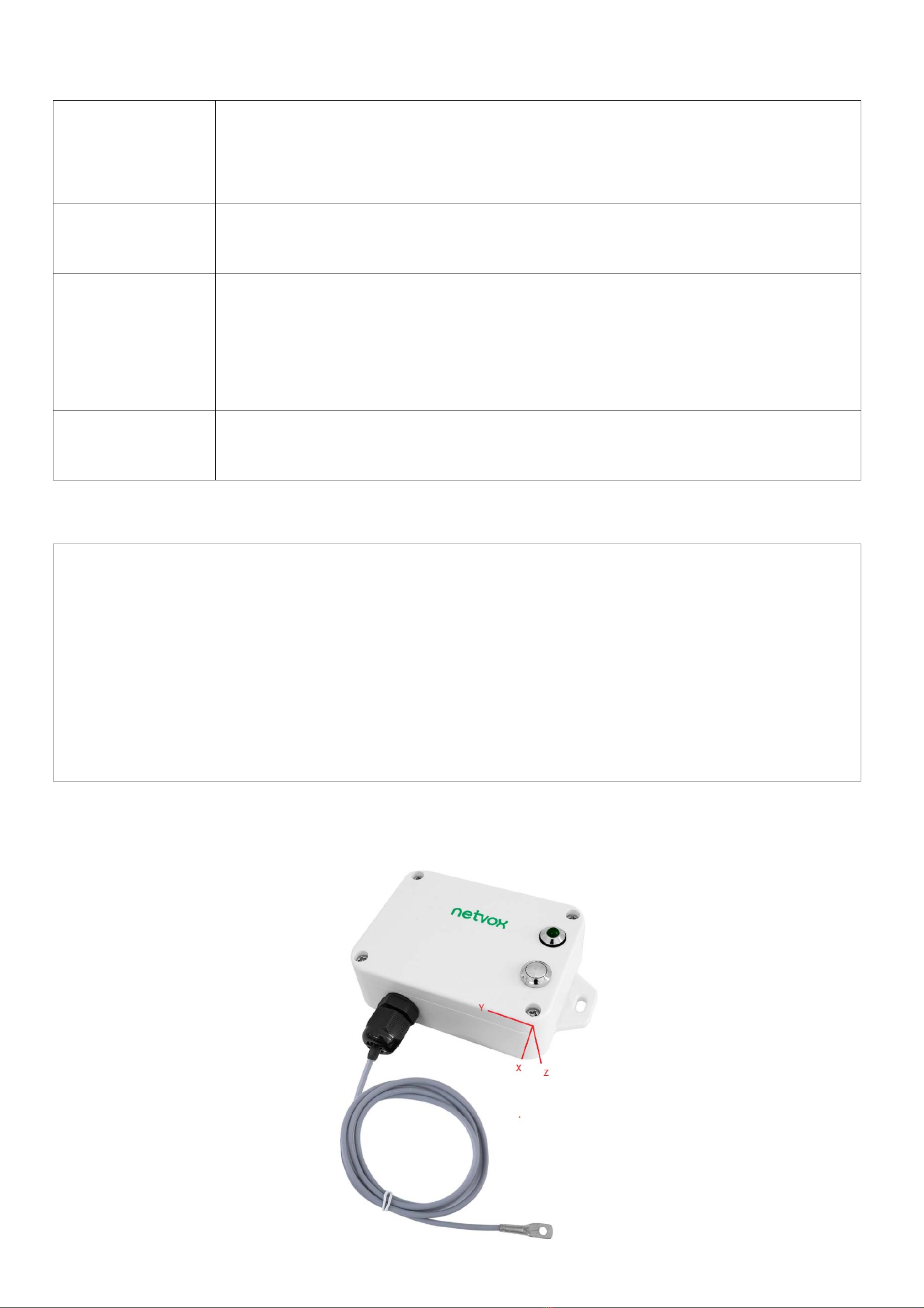
Calibration:
1. The device must be placed horizontally during automatic calibration.
2. After calibration, the angles of X, Y, Z axes are about 0°, 0°, -90° when the device is placed horizontally.
3. There will be no operation when pressing the button before the automatic calibration is completed.
Note:
(1) The device report interval will be programmed based on the default firmware which may vary.
(2) The interval between two reports must be the minimum time.
Please refer Netvox LoRaWANApplication Command document and Netvox Lora Command Resolver
http://cmddoc.netvoxcloud.com/cmddoc to resolve uplink data.

7
5.1 ActiveThreshold and InActiveThreshold
Formula
Active Threshold=Critical value ÷ 9.8÷ 0.0625
The gravitational acceleration at standard atmospheric pressure is 9.8 m/s2
The scale factor of the threshold is 62.5 mg.
Active Threshold Active Threshold can be changed by ConfigureCmd.
Active Threshold range is 0x0003-0x00FF (default is 0x0003);
Inactive time
Inactivetime can be changed by ConfigureCmd.
Inactivetime means that the acceleration variation during the stationary time is less than the set
Inactivetime Threshold to declare stationary.
Inactivetime range is 0x03-0xFF (default is 0x05)
Example Assuming that the critical value is set to 10m/s2, the Active Threshold to be set is 10/9.8/0.0625=16.32
Active Threshold to be set integer as 16.
5.2
Calibration
The accelerometer is a mechanical structure that contains components that can move freely.
These moving parts are very sensitive to mechanical stress, far beyond solid-state electronics.
The 0g offset or offset is an important accelerometer indicator because it defines the baseline used to measure acceleration.
After installing R718EA, turn on the device and wait for the device join the network 1 minute, the device will automatically
offset the calibration.
If the device installation position moves, you need to power off the device 1 minute and restart turn on.
5.3 The X, Y, Z axis direction of R718EA

8
5.4 Example of ReportDataCmd
FPort:0x06
Bytes 1 1 1 Var(Fix=8 Bytes)
Version DeviceType ReportType NetvoxPayLoadData
Version– 1 byte –0x01——the Version of NetvoxLoRaWAN Application Command Version
DeviceType– 1 byte – Device Type of Device
The devicetype is listed in Netvox LoRaWAN Application Devicetype doc
ReportType – 1 byte –the presentation of the NetvoxPayLoadData,according the devicetype
NetvoxPayLoadData– Fixed bytes (Fixed =8bytes)
Device Device
Type
Report
Type NetvoxPayLoadData
R718EA 0x9A
0x00 SoftwareVersion(1Byte)
Eg.0x0A—V1.0
HardwareVersion
(1Byte)
DateCode
(4Bytes,eg 0x20170503)
Reserved
(2Bytes,fixed 0x00)
0x01
Battery
(1Byte,
unit:0.1V)
AngleX
(1Byte Signed
Value,Unit:1°)
AngleY
(1Byte, Signed
Value ,Unit:1°)
AngleZ
(1Byte, Signed
Value ,Unit:1°)
Temperature
(Signed2Bytes,
unit:0.1°C)
Reserved
(2Bytes,fixed
0x00)
Example of Uplink: 019A01240A36E701070000
1st byte (01): Version
2nd byte (9A): DeviceType 0x9A- R718EA
3rd byte (01): ReportType
4th byte (24): Battery-3.6v , 24 Hex=36 Dec 36*0.1v=3.6v
5th byte (0A): AngleX-10°, 0A Hex=10 Dec 10*1°=10°
Tips
1. Battery Voltage:
The voltage value is bit 0 ~ bit 6, bit 7=0 is normal voltage, and bit 7=1 is low voltage.
Battery=0xA0, binary=1010 0000, if bit 7= 1, it means low voltage.
The actual voltage is 0010 0000 = 0x20 = 32, 32*0.1v =3.2v
2. Version Packet:
When Report Type=0x00 is the version packet, such as 019A000A0B202005200000, the firmware version is 2020.05.20
3. Data Packet:
When Report Type=0x01 is data packet.
4. Signed Value:
When the value is negative, 2's complement should be calculated.

9
6th byte (36): AngleY-54° ,36 Hex=54 Dec 54*1°=54°
7th byte (E7): AngleZ--25°, 0x100 Hex -0xE7 Hex = 19 Hex, 19 Hex=25 Dec -25*1°= -25°
8th 9th byte (0107): Temperature-26.3°C , 107 Hex= 263 Dec 263*0.1°C=26.3°
10th 11th byte (0000): Reserved
5.5 Example of data configuration
FPort:0x07
Bytes 1 1 Var(Fix =9 Bytes)
CmdID DeviceType NetvoxPayLoadData
CmdID– 1 byte
DeviceType– 1 byte – Device Type of Device
NetvoxPayLoadData– var bytes (Max=9bytes)
Description Device Cmd
ID Device
Type NetvoxPayLoadData
ConfigReportReq
R718EA
0x01
0x9A
MinTime
(2bytes Unit:s) MaxTime
(2bytes Unit:s)
BatteryChange
(1byte
Unit:0.1v)
AngleChange
(1byte Unit:1°)
Temperature
Change
(1byte
Unit:0.1°C)
Reserved
(2Bytes,Fixed
0x00)
ConfigReportRsp 0x81 Status(0x00_success) Reserved (8Bytes,Fixed 0x00)
ReadConfigReportReq 0x02 Reserved (9Bytes,Fixed 0x00)
ReadConfigReportRsp 0x82 MinTime
(2bytes Unit:s) MaxTime
(2bytes Unit:s)
BatteryChange
(1byte
Unit:0.1v)
AngleChange
(1byte Unit:1°)
Temperature
Change
(1byte
Unit:0.1°C)
Reserved
(2Bytes,Fixed
0x00)
SetActiveThresholdReq 0x03 Threshold
(2Bytes) Inactivetime
(1Byte,Unit:1s) Reserved
(6Bytes,Fixed 0x00)
SetActiveThresholdRsp 0x83 Status
(0x00_success) Reserved
(8Bytes,Fixed 0x00)
GetActiveThresholdReq 0x04 Reserved
(9Bytes,Fixed 0x00)
GetActiveThresholdRsp 0x84 Threshold
(2Bytes) Inactivetime
(1Byte,Unit:1s) Reserved
(6Bytes,Fixed 0x00)
(1)Configure device parameters MinTime = 1min, MaxTime = 1min, BatteryChange = 0.1v, AngleChange =5°,
TemperatureChange=1°C
Downlink: 019A003C003C01050A0000 003C(Hex) = 60(Dec)
Device returns:
819A000000000000000000 (Configuration is successful)
819A010000000000000000 (Configuration failed)

10
(2)Read device parameters
Downlink: 029A000000000000000000
Device returns:
829A003C003C01050A0000 (current device parameters)
(3)Configure device parameters ActiveThreshold=16, Inactivetime =5 seconds
Assuming that the Active Threshold is set to 10m/s2, the value to be set is 10/9.8/0.0625=16.32,and the last value obtained is
an integer and is configured as 16.
Downlink: 039A001005000000000000
Device returns:
839A000000000000000000 (Configuration is successful)
839A010000000000000000 (Configuration failed)
(4)Read device parameters
Downlink: 049A000000000000000000
Device returns:
849A001005000000000000 (Device current parameter)
5.6 Example for MinTime/MaxTime logic
Example#1 based on MinTime = 1 Hour, MaxTime= 1 Hour, Reportable Change i.e. BatteryVoltageChange=0.1V
MaxTime MaxTime
Sleeping(MinTime) Sleeping(MinTime)
Note: MaxTime=MinTime. Data will only be report according to MaxTime (MinTime) duration regardless BatteryVoltageChange
value.
Example#2 based on MinTime = 15 Minutes, MaxTime= 1 Hour, Reportable Change i.e. BatteryVoltageChange= 0.1V.
MaxTime
Sleeping(MinTime) sleeping sleeping sleeping
0H 15th M 30th M 45th M 1H
Wakes up and
collects data
3.6V
Does not report
Wakes up and
collects data
3.6V
Does not report
Wakes up and
collects data
3.6V
Does not report
Wakes up and
collects data
REPORTS 3.6V
Wakes up and
collects data
REPORT 3.6V
Wake up and collects data
REPORTS 3.6V
Wakes up and collects data
REPORTS 3.6V
Wakes up and collects data
REPORTS 3.6V

11
Example#3 based on MinTime = 15 Minutes, MaxTime= 1 Hour, Reportable Change i.e. BatteryVoltageChange= 0.1V.
MaxTime
sleeping sleeping ...
0H 15th M 30th M 45th M 1H 1H 10th M 1H 25th M 1H 40th M 1H 55th M 2H 10th M
Notes:
1) The device only wakes up and performs data sampling according to MinTime Interval. When it is sleeping, it does not
collect data.
2) The data collected is compared with the last data reported. If the data variation is greater than the ReportableChange
value, the device reports according to MinTime interval. If the data variation is not greater than the last data reported, the
device reports according to MaxTime interval.
3) We do not recommend to set the MinTime Interval value too low. If the MinTime Interval is too low, the device wakes up
frequently and the battery will be drained soon.
4) Whenever the device sends a report, no matter resulting from data variation, button pushed or MaxTime interval, another
cycle of MinTime/MaxTime calculation is started.
6. Installation
While installing, it is recommended to install R718EA while the device is power-off, and be installed horizontal at a stationary
place. After installing and fixing R718EA, please turn on the device. After the device is joined, one minute later, R718EA would
perform the offset calibration of the device.
R718EA would need some time to gather the data of three-axis tilt angle, the voltage of battery and the surface temperature for
reference.
The specific configuration depends on the actual situation.
Note:
Please do not disassemble the device unless it is required to replace the batteries. Do not touch the waterproof gasket, LED
indicator light, function keys when replacing the batteries. Please use suitable screwdriver to tighten the screws (if using an
electric screwdriver, it is recommended to set the torque as 4kgf) to ensure the device is impermeable.
Wakes up and
collects data
REPORTS 3.6V
Wakes up and collects data
3.5V |3.5-3.6|=0.1
REPORTS 3.5V
Wakes up and
collects data
3.5V
Does not report
Wakes up and
collects data
3.5V
Does not report
Wakes up and
collects data
3.5V
Does not report
Wakes up and
collects data 3.5V
Does not report
Wakes up and
collects data
3.5V
Does not report
Wakes up and
collects data
REPORTS 3.5V
Wakes up and
collects data
3.6V
Does not report
Users push the button,
REPORTS 3.5V.
Recalculate MaxTime.

12
7. Information about Battery Passivation
Many of Netvox devices are powered by 3.6V ER14505 Li-SOCl2 (lithium-thionyl chloride) batteries that offer many
advantages including low self-discharge rate and high energy density.
However, primary lithium batteries like Li-SOCl2 batteries will form a passivation layer as a reaction between the lithium
anode and thionyl chloride if they are in storage for a long time or if the storage temperature is too high. This lithium chloride
layer prevents rapid self-discharge caused by continuous reaction between lithium and thionyl chloride, but battery passivation
may also lead to voltage delay when the batteries are put into operation, and our devices may not work correctly in this situation.
As a result, please make sure to source batteries from reliable vendors, and it is suggested that if the storage period is more
than one month from the date of battery production, all the batteries should be activated.
If encountering the situation of battery passivation, users can activate the battery to eliminate the battery hysteresis.
ER14505 Battery Passivation:
7.1 To determine whether a battery requires activation
Connect a new ER14505 battery to a resistor in parallel, and check the voltage of the circuit.
If the voltage is below 3.3V, it means the battery requires activation.
7.2 How to activate the battery
a. Connect a battery to a resistor in parallel
b. Keep the connection for 5~8 minutes
c. The voltage of the circuit should be ≧3.3, indicating successful activation.
Brand Load Resistance Activation Time Activation Current
NHTONE 165 Ω 5 minutes 20mA
RAMWAY 67 Ω 8 minutes 50mA
EVE 67 Ω 8 minutes 50mA
SAFT 67 Ω 8 minutes 50mA
Note:
If you buy batteries from other than the above four manufacturers, then the battery activation time, activation current, and
required load resistance shall be mainly subject to the announcement of each manufacturer.
8. Description of Waterproof Grade
1: According to Enclosure Protection Class
This standard is equivalent to IEC 60529:2001 Degrees of Protection Provided by Enclosures (IP Code) (English version)
2: The test method of IP65 waterproof grade is:
Spray the device in all directions under 12.5L/min water flow for 3min, and the internal electronic function is normal.

13
The test method of IP67 waterproof grade is:
The device is immersed in 1m deep water for 30min, and the internal electronic function is normal.
IP65, dust-proof and to prevent damage caused by water from nozzles in all directions from invading electrical appliances. It
can be used in general indoor environment and sheltered outdoor environment. It is not suitable for use in environments with
high water pressure, high temperature and high humidity, such as long time direct sunlight outdoors and possible direct
exposure to rainstorm. If it is really necessary to install in harsh environments, it is recommended to add sunscreen and
rainproof shields when installing.
Case I (face down with LED and buttons) Case II (installed under the rain shield)
9. Important Maintenance Instruction
Kindly pay attention to the following in order to achieve the best maintenance of the product:
•Keep the device dry. Rain, moisture, or any liquid might contain minerals and thus corrode electronic circuits. If the device gets
wet, please dry it completely.
•Do not use or store the device in dusty or dirty environment. It might damage its detachable parts and electronic components.
•Do not store the device under excessive heat condition. High temperature can shorten the life of electronic devices, destroy
batteries, and deform or melt some plastic parts.
•Do not store the device in places that are too cold. Otherwise, when the temperature rises to normal temperature, moisture will
form inside, which will destroy the board.
•Do not throw, knock or shake the device. Rough handling of equipment can destroy internal circuit boards and delicate
structures.
•Do not clean the device with strong chemicals, detergents or strong detergents.
•Do not apply the device with paint. Smudges might block in the device and affect the operation.
•Do not throw the battery into the fire, or the battery will explode. Damaged batteries may also explode.
All of the above applies to your device, battery and accessories.
If any device is not working properly, please take it to the nearest authorized service facility for repair.
Other manuals for R718EA
1
Table of contents
Other netvox Accessories manuals

netvox
netvox R718VA User manual

netvox
netvox R718PB15A User manual

netvox
netvox R718F2 User manual

netvox
netvox R718PQA User manual

netvox
netvox R727 User manual

netvox
netvox R311FA1 User manual

netvox
netvox ZigBee ZB11B User manual

netvox
netvox R311FA User manual

netvox
netvox R718PA4 User manual

netvox
netvox R816B01 User manual

netvox
netvox R809A User manual

netvox
netvox R718G User manual

netvox
netvox R718DB2 User manual

netvox
netvox R313B User manual

netvox
netvox RA0701 User manual

netvox
netvox R718PA5 User manual

netvox
netvox RA0716 User manual

netvox
netvox R718PB13 User manual

netvox
netvox R311FA User manual

netvox
netvox ZigBee Z311G User manual