netvox R718CK2 User manual

Model:R718CK2/CT2/CR2
Wireless 2-Gang Thermocouple Sensor for K/T/R Type
Wireless 2-Gang Thermocouple Sensor
for
K/T/R Type
R718CK2/CT2/CR2
User Manual
Copyright©Netvox Technology Co., Ltd.
This document contains proprietary technical information which is the property of NETVOX Technology. It shall be maintained
in strict confidence and shall not be disclosed to other parties, in whole or in part, without written permission of NETVOX
Technology. The specifications are subject to change without prior notice.

1
Table of Content
1. Introduction.............................................................................................................................................................2
2. Appearance..............................................................................................................................................................3
3. Main Features..........................................................................................................................................................3
4. Set up Instruction ....................................................................................................................................................4
5. Data Report .............................................................................................................................................................5
6. Important Maintenance Instruction.........................................................................................................................9

2
1. Introduction
R718CK2 (nickel-chromium-nickel silicon thermocouple): its use temperature is -40 ~ +375℃, with good linearity, large
thermoelectromotive force, high sensitivity, stability, can not be used directly at high temperature for sulfur, reducing or reducing
It is not recommended for use in weak oxidizing atmospheres in oxidizing alternating atmospheres and in vacuum.
R718CT2 (copper-copper-nickel thermocouple): its use temperature is -40 ~ +125℃, it is used in the temperature range of
-40~0℃, and the stability is better.
R718CR2 (precious metal thermocouple): Its temperature is 0 ~ +1100℃. The R type thermocouple has the highest accuracy, the
best stability, wide temperature range and long service life in the thermocouple series. It has good physical and chemical
properties, good thermoelectric potential stability and high oxidation resistance at high temperatures, and is suitable for oxidizing
and inert atmospheres.
LoRa Wireless Technology:
LoRa is a wireless communication technology dedicated to long distance and low power consumption. Compared with other
communication methods, LoRa spread spectrum modulation method greatly increases to expand the communication distance.
Widely used in long-distance, low-data wireless communications. For example, automatic meter reading, building automation
equipment, wireless security systems, industrial monitoring. Main features include small size, low power consumption,
transmission distance, anti-interference ability and so on.
LoRaWAN:
LoRaWAN uses LoRa technology to define end-to-end standard specifications to ensure interoperability between devices and
gateways from different manufacturers.
3
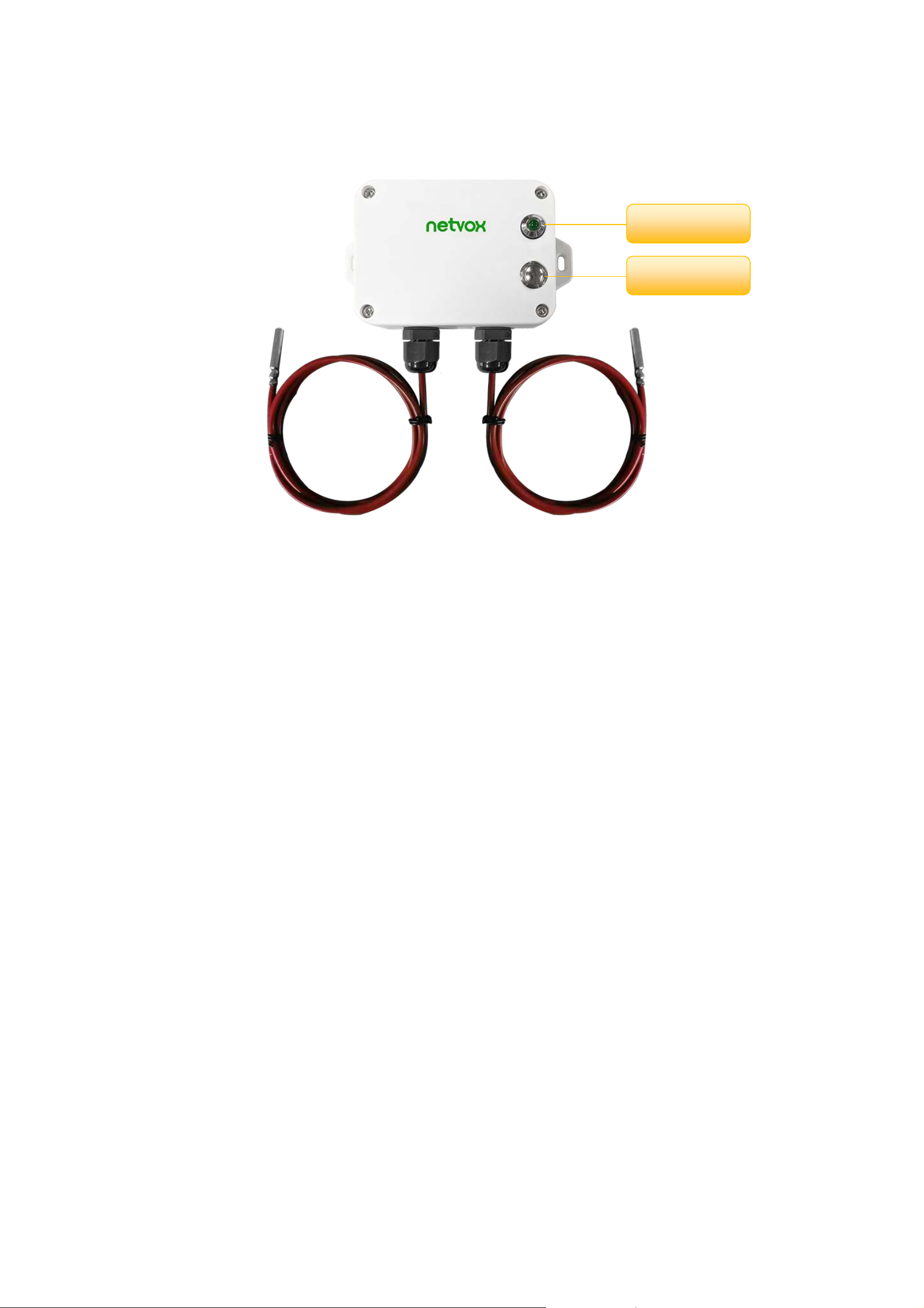
2. Appearance
3. Main Features
Adopt SX1276 wireless communication module
2 ER14505 batteryAAsize (3.6V / section) parallel power supply
Main body protection class IP65/IP67,
External thermocouple sensor protection class:
K-type thermocouple IP60
T-type thermocouple IP67
R-type thermocouple IP60
The base is attached with a magnet that can be attached to a ferrous object
2-way thermocouple detection
Compatible with LoRaWANTM Class A
Frequency hopping spread spectrum
Configuration parameters can be configured via a third-party software platform
Applicable to third-party platforms: Actility / ThingPark, TTN, MyDevices /Cayenne
Low power consumption, longer battery life support*:
Battery life is determined by sensor reporting frequency and other variables,
please refer to http://www.netvox.com.tw/electric/electric_calc.html
On the website, users can find battery life of various models in different configurations.
Indicator
Function Key

4
4.Set up Instruction
On/Off
Power on Insert batteries. (users may need a screwdriver to open)
Turn on Press and hold the function key for 3 seconds till the green indicator flashes once.
Turn off (Restore to factory setting) Press and hold the function key for 5 seconds till green indicator flashes for 20 times.
Power off Remove Batteries.
Note:
1. Remove and insert the battery; the device is at off state by default.
2. On/off interval is suggested to be about 10 seconds to avoid the interference of capacitor
inductance and other energy storage components.
3. At 1st-5th second after power on, the device will be in engineering test mode.
Network Joining
Never joined the network
Turn on the device to search the network to join.
The green indicator stays on for 5 seconds: success
The green indicator remains off: fail
Had joined the network
(Not at factory setting mode)
Turn on the device to search the previous network to join.
The green indicator stays on for 5 seconds: success
The green indicator remains off: fail
Fail to join the network
(when the device is on)
Suggest to check the device verification information on the gateway or consult your platform
server provider.
Function Key
Press and hold for 5 seconds
Restore to factory setting / Turn off
The green indicator flashes for 20 times: success
The green indicator remains off: fail
Press once The device is in the network: green indicator flashes once and sends a report
The device is not in the network: green indicator remains off
Sleeping Mode
The device is on and in the
network
Sleeping period: Min Interval.
When the reportchange exceeds setting value or the state
changes: send a data report according
to Min Interval.
Low Voltage Warning
Low Voltage
3.2
V

5
5. Data Report
Data report configuration and sending period are as following:
Min Interval
(Unit:second)
Max Interval
(Unit:second) Reportable Change Current Change≥
Reportable Change
Current Change<
Reportable Change
Any number between
1~65535
Any number between
1~65535 Can not be 0. Report
per Min Interval
Report
per Max Interval
The device will immediately send a version package report and a report data with temperature and voltage values.
The device sends data in the default configuration before any configuration is done.
Default setting:
Maximum time: Max Interval = 900 seconds
Minimum time: Min Interval = 900 seconds
(by default, the current voltage value is detected per Min Interval)
Battery Change: 0x01 (0.1V)
Temperature Change: 0x00064 (10°C)
Note:
(1)The real data sending cycle will be programmed before shipment.
(2)The interval between two reports must be the minimum time
Please refer Netvox LoRaWAN Application Command document and Netvox Lora Command Resolver
http://loraresolver.netvoxcloud.com:8888/page/index to resolve uplink data.

6
Example of ReportDataCmd
FPort:0x06
Bytes 1 1 1 Var (Fix=8 Bytes)
Version DeviceType ReportType NetvoxPayLoadData
Version– 1 byte –0x01——the Version of NetvoxLoRaWAN Application Command Version
DeviceType– 1 byte – Device Type of Device
The devicetype is listed in Netvox LoRaWAN Application Devicetype doc
ReportType – 1 byte –the presentation of the NetvoxPayLoadData,according the devicetype
NetvoxPayLoadData– Fixed bytes (Fixed =8bytes)
Device DeviceType ReportType NetvoxPayLoadData
R718CK2
R718CT2
R718CR2
0x16
0x17
0x18
0x01 Battery
(1Byte, unit:0.1V) Temperature1
(Signed2Bytes,unit:0.1°C) Temperature2
(Signed2Bytes,unit:0.1°C) Reserved
(3Bytes,fixed 0x00)
Example 1 of Uplink: 0116012400FD0109000000
1st byte (01): Version
2nd byte (16): DeviceType 0x16-R718CK2
3rd byte (01): ReportType
4th byte (24): Battery, 24Hex=36 Dec, 36x0.1v = 3.6v
5th6th byte (00FD): Temperature1, 00FD Hex=253 Dec, 253x0.1°C = 25.3°C
7th8th byte (0109): Temperature2, 0109 Hex=265 Dec, 265x0.1°C = 26.5°C
9th-11th byte (000000): Reserved
Example 2 of Uplink:0117019FFF39FEC5000000
1st byte (01): Version
2nd byte (17): DeviceType 0x17-R718CT2
3rd byte (01): ReportType
4th byte (9F): Battery, 1F Hex = 31 Dec, 31x0.1v=3.1v // the bit7 is 1,represent low battery
5th6th byte (FF39): Temperature1, FF39 Hex= -199 Dec,-199 x 0.1°C = -19.9°C
7th8th byte (FEC5): Temperature2, FEC5 Hex= -315 Dec,-315 x 0.1°C = -31.5°C
//negative numbers represented in 2's complement
9th-11th byte (000000): Reserved

7
Example of ConfigureCmd
FPort:0x07
Bytes 1 1 Var (Fix =9 Bytes)
CmdID DeviceType NetvoxPayLoadData
CmdID– 1 byte
DeviceType– 1 byte – Device Type of Device
NetvoxPayLoadData– var bytes (Max=9bytes)
Description Device Cmd
ID
Device
Type NetvoxPayLoadData
ConfigReport
Req
R718CK2
R718CT2
R718CR2
0x01
0x16
0x17
0x18
MinTime
(2bytes Unit:s) MaxTime
(2bytes Unit:s) BatteryChange
(1byte Unit:0.1v) TemperatureChange
(2byte Unit:0.1℃) Reserved
(2Bytes,Fixed 0x00)
ConfigReport
Rsp 0x81 Status
(0x00_success) Reserved
(8Bytes,Fixed 0x00)
ReadConfig
ReportReq 0x02 Reserved
(9Bytes,Fixed 0x00)
ReadConfig
ReportRsp 0x82 MinTime
(2bytes Unit:s) MaxTime
(2bytes Unit:s) BatteryChange
(1byte Unit:0.1v) TemperatureChange
(2byte Unit:0.1℃) Reserved
(2Bytes,Fixed 0x00)
(1)Configure R718CK2 report parameters:
MinTime = 1min、MaxTime = 1min、BatteryChange = 0.1v、TemperatureChange = 1°C (10*0.1°C)
Downlink:0116003C003C01000A0000 3C(Hex) =60(Dec) 0A(Hex) = 10(Dec)
Response:
8116000000000000000000 (Configuration success)
8116010000000000000000 (Configuration failure)
(2)Read Configuration:
Downlink:0216000000000000000000
Response:
8216003C003C01000A0000 (Current configuration)

8
Example for MinTime/MaxTime logic:
Example#1 based on MinTime = 1 Hour, MaxTime= 1 Hour, Reportable Change i.e. BatteryVoltageChange=0.1V
MaxTime MaxTime
Sleeping(MinTime) Sleeping(MinTime)
Note: MaxTime=MinTime. Data will only be report according to MaxTime (MinTime) duration regardless BatteryVoltageChange
value.
Example#2 based on MinTime = 15 Minutes, MaxTime= 1 Hour, Reportable Change i.e. BatteryVoltageChange= 0.1V.
MaxTime
Sleeping(MinTime) sleeping sleeping sleeping
0H 15th M 30th M 45th M 1H 2H
Example#3 based on MinTime = 15 Minutes, MaxTime= 1 Hour, Reportable Change i.e. BatteryVoltageChange= 0.1V.
MaxTime
sleeping sleeping ...
0H 15th M 30th M 45th M 1H 1H 10th M 1H 25th M 1H 40th M 1H 55th M 2H 10th M
Notes :
1) The device only wakes up and performs data sampling according to MinTime Interval. When it is sleeping, it does not
collect data.
Wakes up and
collects data
3.6V
Does not report
Wakes up and
collects data
3.6V
Does not report
Wakes up and
collects data
3.6V
Does not report
Wakes up and
collects data
REPORTS 3.6V
Wakes up and
collects data
REPORT 3.6V
Wakes up and
collects data
REPORTS 3.6V
Wakes up and collects data
3.5V |3.5-3.6|=0.1
REPORTS 3.5V
Wakes up and
collects data
3.5V
Does not report
Wakes up and
collects data
3.5V
Does not report
Wakes up and
collects data
3.5V
Does not report
Wakes up and
collects data 3.5V
Does not report
Wakes up and
collects data
3.5V
Does not report
Wakes up and
collects data
REPORTS 3.5V
Wake up and collects data
REPORTS 3.6V
Wakes up and collects data
REPORTS 3.6V
Wakes up and collects data
REPORTS 3.6V
Wakes up and
collects data
3.6V
Does not report
Users push the button,
REPORTS 3.5V.
Recalculate MaxTime.

9
2) The data collected is compared with the last data reported. If the data variation is greater than the ReportableChange value,
the device reports according to MinTime interval. If the data variation is not greater than the last data reported, the device
reports according to MaxTime interval.
3) We do not recommend to set the MinTime Interval value too low. If the MinTime Interval is too low, the device wakes up
frequently and the battery will be drained soon.
4) Whenever the device sends a report, no matter resulting from data variation, button pushed or MaxTime interval, another
cycle of MinTime/MaxTime calculation is started.
6. Important Maintenance Instruction
Kindly pay attention to the following in order to achieve the best maintenance of the product:
• Keep the device dry. Rain, moisture, or any liquid, might contain minerals and thus corrode electronic circuits. If the device gets
wet, please dry it completely.
• Do not use or store the device in dusty or dirty environment. It might damage its detachable parts and electronic components.
• Do not store the device under excessive heat condition. High temperature can shorten the life of electronic devices, destroy
batteries, and deform or melt some plastic parts.
• Do not store the device in places that are too cold. Otherwise, when the temperature rises to normal temperature, moisture will
form inside, which will destroy the board.
• Do not throw, knock or shake the device. Rough handling of equipment can destroy internal circuit boards and delicate
structures.
• Do not clean the device with strong chemicals, detergents or strong detergents.
• Do not apply the device with paint. Smudges might block in the device and affect the operation.
• Do not throw the battery into the fire, or the battery will explode. Damaged batteries may also explode.
All of the above applies to your device, battery and accessories. If any device is not working properly, please take it to the nearest
authorized service facility for repair.
This manual suits for next models
2
Table of contents
Other netvox Accessories manuals

netvox
netvox R311LA User manual

netvox
netvox R720FLT User manual

netvox
netvox R718EA User manual

netvox
netvox R718DB2 User manual

netvox
netvox R313M User manual

netvox
netvox R718A User manual

netvox
netvox R718PA5 User manual

netvox
netvox R718EA User manual

netvox
netvox R311B User manual

netvox
netvox Z808B User manual

netvox
netvox R718UBB Series User manual

netvox
netvox R311CA User manual

netvox
netvox R718EB User manual

netvox
netvox R718LB User manual

netvox
netvox R311G User manual

netvox
netvox RA0716 User manual

netvox
netvox R718N1 User manual

netvox
netvox ZigBee Z801WLS User manual

netvox
netvox R718PQ User manual

netvox
netvox RA02C User manual


