netvox R718F User manual
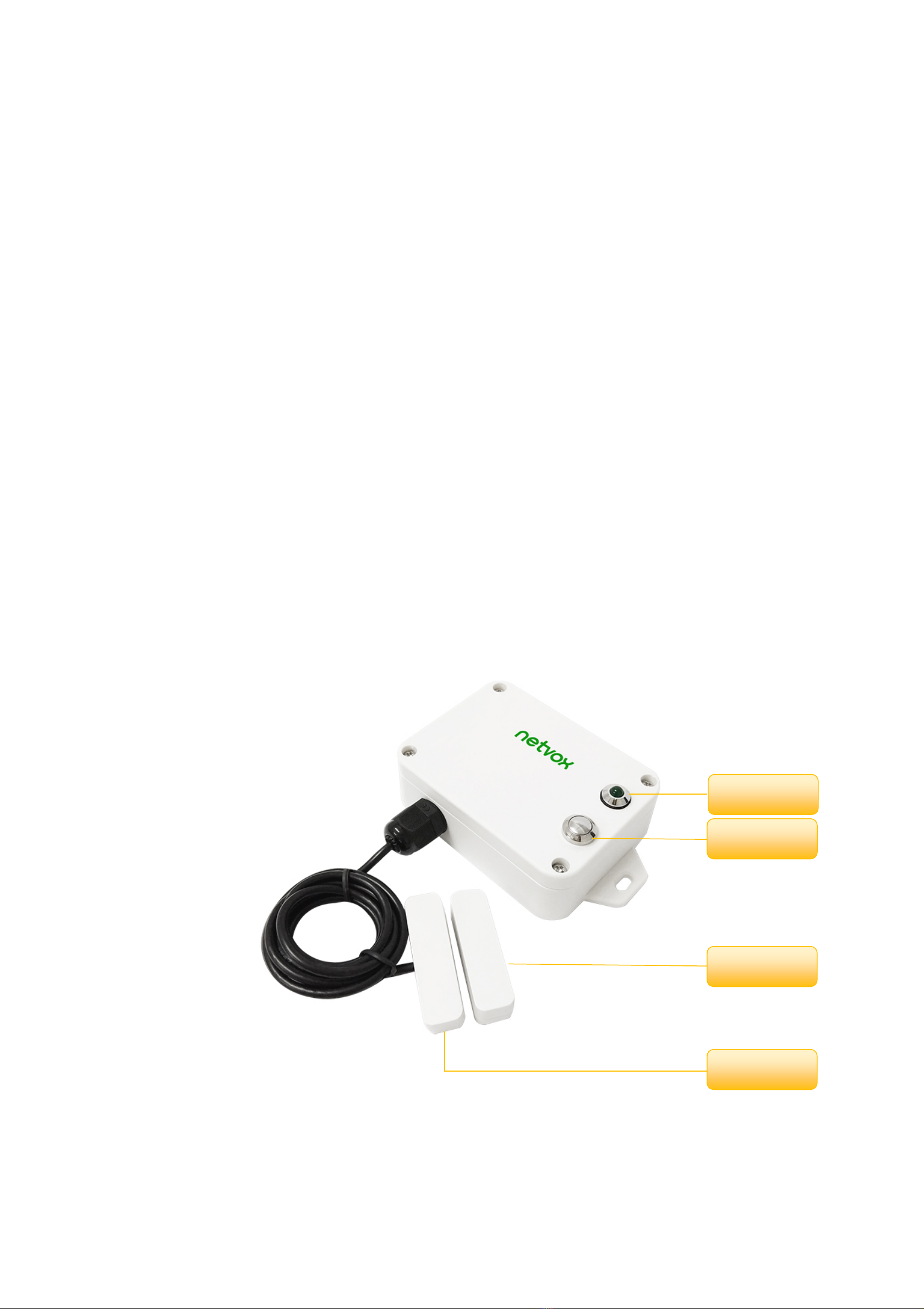
Model:R718F
Wireless Reed Switch Open/Close Detection Sensor
Wireless Reed Switch Open/Close Detection
Sensor
R718F
User Manual
Copyright©Netvox Technology Co., Ltd.
This document contains proprietary technical information which is the property of NETVOX Technology. It shall be maintained in strict
confidence and shall not be disclosed to other parties, in whole or in part, without written permission of NETVOX Technology. The
specifications are subject to change without prior notice.

1
Table of Content
1. Introduction ......................................................................................................................................................................2
2. Appearance ....................................................................................................................................................................... 2
3. Main Features...................................................................................................................................................................3
4. Set up Instruction..............................................................................................................................................................3
5. Data Report.......................................................................................................................................................................5
6. Installation ........................................................................................................................................................................ 8
7. Information about Battery Passivation...........................................................................................................................10
7.1 To determine whether a battery requires activation................................................................................................10
7.2 How to activate the battery ..................................................................................................................................... 10
8. Important Maintenance Instruction................................................................................................................................ 11

2
1. Introduction
R718F is a wireless long-distance reed switch detection device which is Class A devices based on the LoRaWANTM protocol of Netvox
and is compatible with the LoRaWAN protocol.
LoRa Wireless Technology:
LoRa is a wireless communication technology dedicated to long distance and low power consumption. Compared with other
communication methods, LoRa spread spectrum modulation method greatly increases to expand the communication distance. Widely
used in long-distance, low-data wireless communications. For example, automatic meter reading, building automation equipment,
wireless security systems, industrial monitoring. Main features include small size, low power consumption, transmission distance,
anti-interference ability and so on.
LoRaWAN:
LoRaWAN uses LoRa technology to define end-to-end standard specifications to ensure interoperability between devices and gateways
from different manufacturers.
2. Appearance
Indicator
Function Key
Reed Switch
Magnet

3
3. Main Features
Adopt SX1276 LoRa wireless communication module
2 ER14505 battery AA SIZE (3.6V / section) parallel power supply
Trigger the magnetic sensor, and the device can send the alarm
The base is attached with a magnet that can be attached to a ferromagnetic material object
Host body protection class IP65/67 (optional)
Compatible with LoRaWANTM Class A
Frequency hopping spread spectrum
Configuration parameters can be configured via a third-party software platform, data can be read and alerts can be set via SMS text
and email (optional)
Applicable to third-party platforms: Actility/ThingPark, TTN, MyDevices/Cayenne
Low power consumption and long battery life
Note*:
Battery life is determined by the sensor reporting frequency and other variables, please refer to
http://www.netvox.com.tw/electric/electric_calc.html
On this website, users can find battery life of various models in different configurations.
4.Set up Instruction
On/Off
Power on Insert batteries. (users may need a screwdriver to open)
Turn on Press and hold the function key for 3 seconds till the green indicator flashes once.
Turn off (Restore to factory setting) Press and hold the function key for 5 seconds and the green indicator flashes 20 times.
Power off Remove Batteries.
Note:
1. Remove and insert the battery: the device is in the turn-off state by default.
2. The first 5 seconds after power on, the device is in engineering testing mode.
3. Every time, after remove and reinsert the battery, the device is in a turn-off state and
need to power on again.
4. On/off interval is suggested to be about 10 seconds to avoid the interference of
capacitor inductance and other energy storage components.

4
Network Joining
Never joined the network
Turn on the device to search the network.
The green indicator stays on for 5 seconds: success
The green indicator remains off: fail
Had joined the network
(Not restore to the factory setting)
Turn on the device to search the previous network.
The green indicator stays on for 5 seconds: success
The green indicator remains off: fail
Fail to join the network
1. Suggest removing batteries if the device is not used to save power.
2. Suggest checking the device registration information on the gateway
or consulting your platform server provider if the device fails to join the network.
Function Key
Press and hold for 5 seconds
Restore to factory setting / Turn off
The green indicator flashes 20 times: success
The green indicator remains off: fail
Press once The device is in the network: green indicator flashes once and sends a report
The device is not in the network: green indicator remains off
Sleeping Mode
The device is on and in the network
Sleeping period: Min Interval.
When the reportchange exceeds setting value or the state changes: send a data report
according to Min Interval.
The device is turn on but not join in the
network
1. Suggest removing batteries if the device is not used to save the power.
2. Suggest checking the device registration information on the gateway.
Low Voltage Warning
Low Voltage 3.2V

5
5. Data Report
Data report configuration and sending period are as following:
Min Interval
(Unit:second)
Max Interval
(Unit:second) Reportable Change Current Change≥
Reportable Change
Current Change<
Reportable Change
Any number between
1~65535
Any number between
1~65535 Can not be 0 Report
per Min Interval
Report
per Max Interval
The device will immediately send a version packet report along with an uplink packet including reed switch status and battery
voltage.
The device sends data according to the default configuration before any other configuring.
Default setting:
MaxTime : Max Interval = 60 min = 3600s
MinTime : Min Interval = 60 min = 3600s (Default: Every Min Interval will detect the current voltage.)
BatteryVoltageChange: 0x01 (0.1V)
Reed switch trigger status:
When the magnet closes to the reed switch, it will report the status “0”
*The distance between the magnet and the reed switch is less than 2 cm
When the magnet removes the reed switch, it will report the status “1”
*The distance between the magnet and the reed switch is greater than 2 cm
Note:
The cycle of the device sending the data report is according to the default.
The interval between two reports must be the Mintime.
Please refer Netvox LoRaWAN Application Command document and Netvox Lora Command Resolver
http://loraresolver.netvoxcloud.com:8888/page/index to resolve uplink data.

6
Example of ConfigureCmd
FPort:0x07
Bytes 1 1 Var (Fix =9 Bytes)
CmdID DeviceType NetvoxPayLoadData
CmdID– 1 byte
DeviceType– 1 byte – Device Type of Device
NetvoxPayLoadData– var bytes (Max=9bytes)
1. Configure device parameters MinTime = 1min, MaxTime = 1min, BatteryChange = 0.1v
Downlink: 011D003C003C0100000000
Device returns:
811D000000000000000000 (configuration successful)
811D010000000000000000 (configuration failed)
2. Read device parameters
Downlink: 021D000000000000000000
Device returns:
821D003C003C0100000000 (current configuration parameters)
Description Device CmdID Device
Type NetvoxPayLoadData
ConfigReport
Req
R718F
0x01
0x1D
MinTime
(2bytes Unit: s) MaxTime
(2bytes Unit: s) BatteryChange
(1byte Unit: 0.1v) Reserved
(4Bytes, Fixed 0x00)
ConfigReport
Rsp 0x81 Status
(0x00_success) Reserved
(8Bytes, Fixed 0x00)
ReadConfig
ReportReq 0x02 Reserved
(9Bytes, Fixed 0x00)
ReadConfig
ReportRsp 0x82 MinTime
(2bytes Unit: s) MaxTime
(2bytes Unit: s) BatteryChange
(1byte Unit: 0.1v) Reserved
(4Bytes, Fixed 0x00)

7
Example for MinTime/MaxTime logic:
Example#1 based on MinTime = 1 Hour, MaxTime= 1 Hour, Reportable Change i.e. BatteryVoltageChange=0.1V
MaxTime MaxTime
Sleeping(MinTime) Sleeping(MinTime)
Note: MaxTime=MinTime. Data will only be report according to MaxTime (MinTime) duration regardless BatteryVoltageChange value.
Example#2 based on MinTime = 15 Minutes, MaxTime= 1 Hour, Reportable Change i.e. BatteryVoltageChange= 0.1V.
MaxTime
Sleeping(MinTime)sleeping sleeping sleeping
0H 15th M 30th M 45th M 1H 2H
Example#3 based on MinTime = 15 Minutes, MaxTime= 1 Hour, Reportable Change i.e. BatteryVoltageChange= 0.1V.
MaxTime
sleeping sleeping ...
0H 15th M 30th M 45th M 1H 1H 10th M 1H 25th M 1H 40th M 1H 55th M 2H 10th M
Notes :
1) The device only wakes up and performs data sampling according to MinTime Interval. When it is sleeping, it does not collect data.
2) The data collected is compared with the last data reported. If the data variation is greater than the ReportableChange value, the device reports
according to MinTime interval. If the data variation is not greater than the last data reported, the device reports according to MaxTime interval.
3) We do not recommend to set the MinTime Interval value too low. If the MinTime Interval is too low, the device wakes up frequently and the battery
will be drained soon.
4) Whenever the device sends a report, no matter resulting from data variation, button pushed or MaxTime interval, another cycle of MinTime/MaxTime
calculation is started.
Wakes up and
collects data
3.6V
Does not report
Wakes up and
collects data
3.6V
Does not report
Wakes up and
collects data
3.6V
Does not report
Wakes up and
collects data
REPORTS 3.6V
Wakes up and
collects data
REPORT 3.6V
Wakes up and
collects data
REPORTS 3.6V
Wakes up and collects data
3.5V |3.5-3.6|=0.1
REPORTS 3.5V
Wakes up and
collects data
3.5V
Does not report
Wakes up and
collects data
3.5V
Does not report
Wakes up and
collects data
3.5V
Does not report
Wakes up and
collects data 3.5V
Does not report
Wakes up and
collects data
3.5V
Does not report
Wakes up and
collects data
REPORTS 3.5V
Wake up and collects data
REPORTS 3.6V
Wakes up and collects data
REPORTS 3.6V
Wakes up and collects data
REPORTS 3.6V
Wakes up and
collects data
3.6V
Does not report
Users push the button,
REPORTS 3.5V.
Recalculate MaxTime.

8
6. Installation
1. R718F has a built-in magnet (as the figure below). When
installed, it can be attached to the surface of an object with
iron which is convenient and quick.
To make the installation more secure, use screws (purchased
separately) to secure the unit to a wall or other surface (as the
figure below).
Note:
Do not install the device in a metal shielded box or in an
environment with other electrical equipment around it to
avoid affecting the wireless transmission of the device.
R718F is suitable below scenarios:
Door, window
Machine room door
Archives
Closet
Refrigerators and freezers
Cargo ship hatch
Garage door
Public toilet door
The place needs to detect the opening and closing status.
2. When the door or window is opened, the reed switch
probe is separated from the magnet, and the device sends
an alarm message about the opening.
When the door or window is closed, the reed switch probe
and the magnet get closer, and the device restores to the
normal state and sends a state message about the closing.
2. Tear off the 3M glue at the bottom of the reed switch probe
and the magnet (as the red frame in the figure above). Then,
stick the reed switch probe to the door and is parallel to the
magnet (as the figure on the right).
Note: The installation distance betwee
n the reed switch probe
and the magnet should be less than 2cm.
Magnet
Reed Switch

9
When installing the device, the magnet must move along the X axisrelative to the sensor.
If the magnet moves along the Y axis relative to the sensor, it will cause repeated reports due to the magnetic field.
Note:
Please do not disassemble the device unless it is required to replace the batteries.
Do not touch the waterproof gasket, LED indicator light, function keys when replacing the batteries. Please use suitable screwdriver to
tighten the screws (if using an electric screwdriver, it is recommended to set the torque as 4kgf) to ensure the device is impermeable.

10
7. Information about Battery Passivation
Many of Netvox devices are powered by 3.6V ER14505 Li-SOCl2 (lithium-thionyl chloride) batteries that offer many advantages
including low self-discharge rate and high energy density.
However, primary lithium batteries like Li-SOCl2 batteries will form a passivation layer as a reaction between the lithium anode and
thionyl chloride if they are in storage for a long time or if the storage temperature is too high. This lithium chloride layer prevents rapid
self-discharge caused by continuous reaction between lithium and thionyl chloride, but battery passivation may also lead to voltage
delay when the batteries are put into operation, and our devices may not work correctly in this situation.
As a result, please make sure to source batteries from reliable vendors, and the batteries should be produced within the last three
months.
If encountering the situation of battery passivation, users can activate the battery to eliminate the battery hysteresis.
7.1 To determine whether a battery requires activation
Connect a new ER14505 battery to a 68ohm resistor in parallel, and check the voltage of the circuit.
If the voltage is below 3.3V, it means the battery requires activation.
7.2 How to activate the battery
a. Connect a battery to a 68ohm resistor in parallel
b. Keep the connection for 6~8 minutes
c. The voltage of the circuit should be ≧3.3V

11
8. Important Maintenance Instruction
The device is a product with superior design and craftsmanship and should be used with care.
The following suggestions will help you use the warranty service effectively.
• Keep the equipment dry. Rain, moisture and various liquids or water may contain minerals that can corrode electronic
circuits. In case the device is wet, please dry it completely.
• Do not use or store in dusty or dirty areas. This way can damage its detachable parts and electronic components.
• Do not store in excessive heat place. High temperatures can shorten the life of electronic devices, destroy batteries, and
deform or melt some plastic parts.
• Do not store in excessive cold place. Otherwise, when the temperature rises to normal temperature, moisture will form
inside which will destroy the board.
• Do not throw, knock, or shake the device. Treating equipment roughly can destroy internal circuit boards and delicate
structures.
• Do not wash with strong chemicals, detergents, or strong detergents.
• Do not paint the device. Smudges can make debris block detachable parts up and affect normal operation.
• Do not throw the battery into the fire to prevent the battery from exploding. Damaged batteries may also explode.
All the above suggestions apply equally to your device, batteries, and accessories.
If any device is not operating properly.
Please take it to the nearest authorized service facility for repairing.
Table of contents
Other netvox Accessories manuals

netvox
netvox R718N3 User manual

netvox
netvox R313G User manual

netvox
netvox R711 User manual

netvox
netvox R718DB User manual

netvox
netvox R311FA User manual

netvox
netvox R718DB2 User manual

netvox
netvox R718PB15 User manual

netvox
netvox R311CA User manual

netvox
netvox R809A User manual

netvox
netvox R313K User manual

netvox
netvox R727 User manual

netvox
netvox R311A User manual

netvox
netvox R718PA Series User manual

netvox
netvox R718PG User manual

netvox
netvox R313B User manual

netvox
netvox R718B1 Series User manual

netvox
netvox R718PB15A User manual

netvox
netvox R718PE User manual

netvox
netvox R718PA4 User manual

netvox
netvox RA0701 User manual