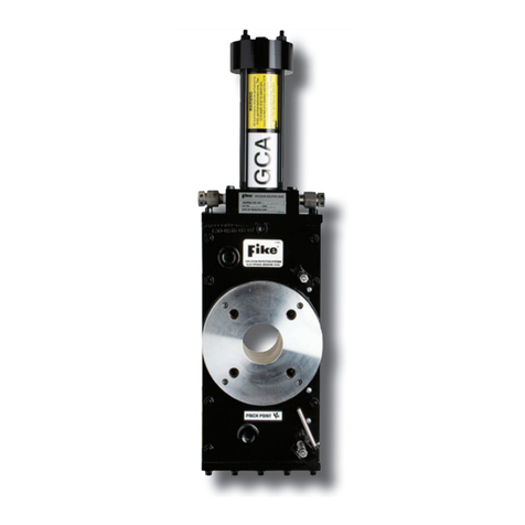
Fike FAV User manual

SOLUTIONS
Fire Protection
Explosion Protection
Overpressure Protection
Pressure Activation
INSTALLATION AND MAINTENANCE INSTRUCTIONS
Explosion Isolation
Valve - FAV
EXPLOSION PROTECTION SYSTEMS
Doc. 8.8503.00.9
Rev. April, 2018

Doc. 8.8503.00.9
Rev. April, 2018
PAGE / 2
COPYRIGHT INFORMATION
© Copyright 2017, Fike Corporation. All rights reserved. Printed in Europe.
This document may not be reproduced, in whole or in part, by any means without the prior written consent of Fike. All
Fike documentation and hardware are copyrighted with all rights reserved.
TRADEMARKS
Fikeis a registered trademark of Fike. All other trademarks, trade names or company names referenced herein are
the property of their respective owners.
ERRORS AND OMISSIONS
While every precaution has been taken during the preparation of this document to ensure the accuracy of its content,
Fike assumes no responsibility whatsoever for errors or omissions.
Fike reserves the right to change product designs or specifications without obligation and without further notice in
accordance with our policy of continuing product and system improvement.
READER QUESTIONS AND RESPONSES
If you have any questions regarding the information contained in this document, or if you have any other enquiries
regarding Fike products, please call Fike Europe Product Support at 0032 14 21 00 31.
Fike encourages input from our distributors and end users on how we can improve this manual and even the product
itself. Please direct all calls of this nature to Fike Europe Product Support at 0032 14 21 00 31. Any communication
received becomes the property of Fike.
TERMS AND CONDITIONS OF SALE
Because of the many and varied circumstances and extreme conditions under which Fike’s products are used, and
because Fike has no control over this actual use, Fike makes no warranties based on the contents of this document.
FIKE MAKES NO IMPLIED WARRANTIES OF MERCHANTABILITY OR FITNESS FOR A SPECIFIC PURPOSE. Refer to
www.fike.com/terms-conditions for Fike’s full TERMS AND CONDITIONS OF SALE.
TERMS OF USE
Do not alter, modify, copy, or otherwise misappropriate any Fike product, whether in whole or in part. Fike assumes
no responsibility for any losses incurred by you or third parties arising from such alteration, modification, copy or
otherwise misappropriation of Fike products.
Do not use any Fike products for any application for which it is not intended. Fike shall not be in any way liable for any
damages or losses incurred by you or third parties arising from the use of any Fike product for which the product is not
intended by Fike.
You should install and use the Fike products described in this document within the range specified by Fike, especially
with respect to the product application, maximum ratings, operating supply voltage range, installation and other
product characteristics. Fike shall have no liability for malfunctions or damages arising out of the use of Fike products
beyond such specified ranges.
You should install and use the Fike products described in this document in compliance with all applicable laws,
standards, and regulations in the country of installation. Fike assumes no liability for damages or losses occurring as a
result of your noncompliance with regionally applicable laws and regulations.
It is the responsibility of the buyer or distributor of Fike products, who distributes, disposes of, or otherwise places the
product with a third party, to notify such third party in advance of the contents and conditions set forth in this
document. Fike assumes no responsibility for any losses incurred by you or third parties as a result of unauthorised
use of Fike products.
QUALITY NOTICE
Fike has maintained ISO 9001 certification since 1996. Prior to shipment, we thoroughly test our products and review
our documentation to assure the highest quality in all respects.

Doc. 8.8503.00.9
Rev. April, 2018
PAGE / 1
TABLE OF CONTENTS
Section Page No.
1. INTRODUCTION .......................................................................................................................................................... 2
1.1. Scope................................................................................................................................................................. 2
2. WARNINGS.................................................................................................................................................................. 4
3. FAST ACTING VALVE.................................................................................................................................................... 5
3.1. Description ........................................................................................................................................................ 5
3.2. Identification ..................................................................................................................................................... 6
3.3. Composing Parts ............................................................................................................................................... 7
3.4. Dimensions........................................................................................................................................................ 8
4. VALVE ACTUATOR ASSEMBLY SAFETY PROCEDURES................................................................................................ 10
5. FAST ACTING VALVE INSTALLATION ......................................................................................................................... 11
5.1. Mechanical Installation ................................................................................................................................... 11
5.2. Electrical installation ....................................................................................................................................... 12
5.2.1. Electrical scheme open/close module (Optional)....................................................................................... 12
5.2.2. Position indicators piston ........................................................................................................................... 12
5.3. Valve Actuator Assembly Installation Procedure ............................................................................................ 13
5.4. Valve Actuator Assembly Removal Procedure ................................................................................................ 13
6. VALVE REFURBISHMENT........................................................................................................................................... 14
6.1. Valve Actuator Assembly Handling Warning................................................................................................... 14
6.2. FAV Maintenance............................................................................................................................................ 14
6.2.1. Actuating Cylinder Rebuild ......................................................................................................................... 14
6.2.2. Gate Damper Replacement (DN50 –DN200 FAV) ...................................................................................... 14
6.2.3. Gate Damper Replacement (DN250 –DN500 FAV) .................................................................................... 15
6.3. Roll Pin Replacement ...................................................................................................................................... 15
6.4. Flange O-Ring Replacement ............................................................................................................................ 15
6.5. Flange to FAV Assembly .................................................................................................................................. 16
6.6. Muffler Seal Replacement............................................................................................................................... 16
6.7. Refurbish Kits .................................................................................................................................................. 16
7. SCHEDULED MAINTENANCE ..................................................................................................................................... 18
7.1. Every Three (3) Months................................................................................................................................... 18
7.2. Every Ten (10) Years........................................................................................................................................ 18
7.2.1. Service Environment................................................................................................................................... 18
8. DE-COMMISSIONING PROCEDURE / CHECK-LIST ..................................................................................................... 19
9. REPAIR AND RETURN AUTHORISATION.................................................................................................................... 20

Doc. 8.8503.00.9
Rev. April, 2018
PAGE / 2
Scope
This document is intended to provide information and assist with the maintenance of Fike Europe Fast Acting Valves
(FAV). Individuals should read this manual carefully. Specific sections will be of particular interest depending upon
specific responsibilities. This information shall be used in conjunction with the drawings and additional information
provided for the specific application.
Fike Explosion Isolation Concept
The risk of an industrial explosion occurs in many stages of production, transport, and storage of combustible dusts
and gases. Apart from all the known preventive measures to avoid conditions, in which explosions may occur, a large
number of constructive protection measures can be taken.
Protective techniques are classified into explosion venting, suppression and isolation.
Explosion venting and explosion suppression are designed to protect process vessels from overpressurisation.
Explosion isolation is intended to keep explosions from spreading throughout a process. By isolating the explosion, the
effect of an explosion is limited to the equipment where the explosion initially occurred.
Responsive mechanical explosion isolation systems, commonly referred to as Fast Acting valves (FAV), are designed to
act upon the detection at the incipient stage of combustion by mechanically isolating the combustion and preventing
flame propagation.
The Fike Explosion Isolation System proceeds through 3 basic sequences to provide successful activation: detection,
initiation and closure of the valve. The Fike Fast Acting valve is the critical element in the sequence of successful
explosion isolation. The rapid closure provides the physical barrier which prevents flame propagation beyond the
isolating valve location.
Refer to Fike documents X.2.32.01-x Fast Acting Valve - FAV, X.2.66.01-x FAV Reload Kit, and X.2.26.01-x Valve
Actuator Assembly for detailed information.
Definitions
FAV:Fast Acting Valve
Explosion: The propagation of a flame in a premixed dispersion of combustible gases, dusts, mists or mixtures of
these, in a gaseous oxidant such as air in a closed or substantially closed vessel.
Deflagration: Explosions which propagate because of heat transfer and having two distinctive and separate parts - a
pressure wave and a flame. The deflagration type of explosion is generally referred to as a combustion reaction where
the flame front burns into the unburned material at a velocity lower than the speed of sound. The Fike hardware is
designed to provide protection against deflagrations only, not against detonations unless otherwise specified.
Explosion sensor: Device that is responsive to the changes of environmental parameters such as pressure caused by a
developing explosion.
Activation pressure Pa:That pressure threshold, above the pressure at ignition of the reactants (Pi), at which a
detection of the explosion is deemed to have occurred.

Doc. 8.8503.00.9
Rev. April, 2018
PAGE / 3
Explosion detector: Device or arrangement of apparatus, containing one or more explosion sensors, that responds to
a developing explosion by providing an explosion detection signal.
Response time: The time necessary for actuation of the system after a detection of an explosion.
Active Explosion Isolation System: A system which is designed to be activated by a sensor/or a control and indicating
equipment (CIE) and stop explosions from travelling through pipelines or limit destructive effects of the explosion.
Actuator: Initiating device, typically a gas generator (Valve Actuator Assembly –GCA).
Control and indicating Equipment (CIE): Equipment which records and monitors the signals transmitted by explosion
pressure sensors / detectors spark and flame, temperature and other safety sensors. Depending on configuration, by
interrogation and interpretation of the detector / sensor data the CIE selectively controls the actuation of Suppressors,
extinguishing barriers, fast closing isolation valves, process equipment shut down, water spray or extinguishing
release, and all audible and visual alarms. The CIE must be constructed according to special specifications.
Explosion Protection System Controller (EPSC): Fike equivalent name for CIE.
Armed: the EPSC is active and will process a detection signal.
Disarmed: the EPSC is inactive and will not process a detection signal.
Shutdown: Disarm action followed by the discharging of the capacitors of a CIE/EPSC. Consequently, the power to fire
the actuator is no longer present. Therefore, shutdown is safer than DISARM. Shutdown must be used during
maintenance to an area of plant, where people can enter the protected volume. Shutdown also guarantees a safe
state of the circuitry for the operator or technician for maintenance or measurements.
Fike Service Sign:
The sections marked with this icon require specialist assistance.
ONLY CERTIFIED FIELD SERVICE ENGINEERS SHALL PERFORM THE ACTIONS DESCRIBED IN THESE MARKED SECTIONS.
Service Qualifications
The information contained in this document is provided for reference purposes only. For further product information
or ordering replacement parts, please contact your local Fike Branch Office or Representative (details of which can be
found on the back page) or Fike Product Support by calling 816-229-3405 (fax: 816-229-0314) or Fike Europe Product
Support at +32 14 21 00 31 (fax: +32 14 21 07 43).

Doc. 8.8503.00.9
Rev. April, 2018
PAGE / 4
WARNING: ISOLATION SYSTEM PARTS ARE NOT DESIGNED TO BE EXPOSED TO VIBRATIONS. FOR MORE DETAILS OR
IN CASE OF DOUBT CONTACT FIKE.
WARNING: ONLY QUALIFIED FIKE PERSONNEL HAVE THE AUTHORITY TO INSTALL / REMOVE ACTUATORS.
WARNING: IN MANY COUNTRIES THE TRANSPORT, STORAGE AND USE OF ACTUATORS ARE CONTROLLED BY
GOVERNMENT RULES AND OFFICES. THE LOCAL AUTHORITIES MUST BE CONSULTED BEFORE
TRANSPORT, USE OR INSTALLATION OF THESE DEVICES AND THE RELEVANT PERMITS OBTAINED
WARNING: ACTUATORS ARE PYROTECHNIC DEVICES THAT CAN CAUSE BODILY INJURY AND / OR EQUIPMENT
DAMAGE IF NOT HANDLED CORRECTLY. ONLY AUTHORIZED PERSONS SHALL WORK WITH THESE DEVICES
AND MUST BE FAMILIAR WITH AND UNDERSTAND THE RELEVANT PROCEDURES.
WARNING: TO PREVENT POSSIBLE INJURY, THE ACTUATOR MUST BE DISCONNECTED AND SHUNTED WHENEVER
PERFORMING ANY OF THE REFURBISHMENT AND REBUILD PROCEDURES.
WARNING: IN NORMAL CIRCUMSTANCES, ACTUATORS ARE THE LAST PART TO BE INSTALLED AND MAY ONLY BE
INSTALLED WHEN EQUIPMENT AND SYSTEM HAVE BEEN CHECKED.
WARNING: ALL MAINTENANCE WORK SHOULD BE EXECUTED BY CERTIFIED FIELD SERVICE ENGINEERS.
ONLY COMPONENTS SUPPLIED BY FIKE i.e. RELOAD KITS, SPARE PARTS ETC., SHOULD BE USED TO
REFURBISH THE CONTAINERS.
FIKE SHALL NOT BE LIABLE FOR CONSEQUENTIAL DAMAGES TO FIKE ASSEMBLIES, COMPONENT PARTS
OR HARM TO PERSONNEL IF WORK TO THE FIKE EQUIPMENT IS CARRIED OUT BY NONE FIKE CERTIFIED
ENGINEERS.
THE SECTIONS MARKED WITH THIS ICON REQUIRE SPECIALIST ASSISTANCE. PLEASE CONTACT FIKE FOR
INFORMATION, ASSISTANCE OR SERVICE TRAINING PROGRAMS.
WARNING: FOR THE USE OF THE EQUIPMENT ON DUST, IGNITION HAZARDS RELATED TO STATIC ELECTRICITY NEEDS
NO ADDITIONAL MEASURES. THE ATEX APPROVALS DOES NOT COVER GASES.

Doc. 8.8503.00.9
Rev. April, 2018
PAGE / 5
The Fike Mechanical Explosion Isolation system typically comprises an EPC controller, explosion pressure detectors of
type UC2 and explosion isolation valves (EIV or FAV) eventually combined with chemically isolation containers
depending the nature of the explosion hazard. Explosion isolation system as a protection system, suitable for use on
process equipment containing dust atmospheres without external hazardous gas atmosphere areas.
The Fike Explosion Isolations Valves are designed to act upon the detection at the incipient stage of a combustion, and
mechanically isolate the combustion. The system suitable for dust –air mixtures with a deflagration index or
equivalent Kst less than 330 bar*m*s-1 (DN50-DN250) or 200 bar*m*s-1 (DN300-DN400) and maximum explosion
overpressure Pmax <12 barg.
The following valve sizes are covered: DN50, DN80, DN100, DN150, DN200, DN250, DN300, DN350, DN400
Minimum distances Xmin and Maximum distances Xmax of the valve in meters from protected vessel.
Protection method for connected
Containment
Venting or suppression
Pmax, Pred max
12 barg
3-4 barg
DN of the isolation valve in mm
Xmin
Xmax
Xmin
Xmax
50 to 100
To be
calculated by
IsolCalc.
75 x Dia
To be
calculated by
IsolCalc.
75 x Dia
150 to 250
50 x Dia
50 x Dia
300 to 400
1.5 x Xmin
2 x Xmin
On detection of an incipient explosion, the CIE (control and indicating equipment) activates the explosion isolation
system and initiates alarm systems. Control and detection of the combustion may be done by one of the following
devices in combination with CIE type EPC.
The FAV is in compliance with: EN 1127-1, EN 13463-1:2009 & EN 15089:2009.

Doc. 8.8503.00.9
Rev. April, 2018
PAGE / 6
To identify the FAV and order replacement parts, the FAV and its driving container have been permanently labeled.
The FAV is tagged with a name sticker (fig. 1).
Figure 1 - Sticker Fast Acting Valve (FAV)
The CE name plate on the valve body contains among other following information: Model, Serial No, Size and Date of
Manuf. (fig. 2).
Figure 2 - Valve Identification Plate
Figure 3 shows the pinch point sticker (on the valve body) a warning against pinching or injury.
Figure 3 - Pinch Point Warning

Doc. 8.8503.00.9
Rev. April, 2018
PAGE / 7
Table 1 - Composing parts
Figure 4 - FAV composing parts
N°
Description
Junction box (with Valve Actuator
Assembly inside)
Exhaust valve (muffler)
Roll pin plug
Gate damper
Bottom cover plate
Upper end cap
Cylinder
Lower end cap
Flange
FAV identification plate

Doc. 8.8503.00.9
Rev. April, 2018
PAGE / 8
Figure 5 - Dimensions

Doc. 8.8503.00.9
Rev. April, 2018
PAGE / 9
Table 2 - Dimensions different sizes FAV
Valve
Size
Valve
Actuator
Assembly
Qty
ANSI
bolting
Bolt
diameter
Max.
torque
(Nm)
ID
(mm)
BC
(mm)
A
(mm)
B
(mm)
C
(mm)
D
(mm)
Weight
(kg)
DIN
Bolting
2”
1
150
5/8 –11 UNC
190
50.8
120.6
165
786
112
122
45
DN50
PN10/16
M16 x 2
195
50.8
120.6
3”
1
150
5/8 –11 UNC
190
78.6
180.0
229
994
111
238
80
DN80
PN10/16
M16 x 2
195
82.5
180.0
4”
1
150
5/8 –11 UNC
190
101.6
180.0
229
994
111
238
80
DN100
PN10/16
M16 x 2
195
101.6
180.0
5”
1
150
¾ - 10UNC
360
131.7
210.0
285
1271
126
329
80
DN125
PN10/16
M20 x 2.5
380
152.4
240.0
6”
1
150
¾ -10 UNC
360
152.4
241.4
285
1271
126
329
100
DN150
PN10/16
M20 x 2.5
380
152.4
240.0
8”
2
150
¾ -10 UNC
360
202.7
298.4
343
1481
126
405
180
DN200
PN16
M20 x 2.5
380
203.2
295.0
10”
2
150
7/8 –9 UNC
640
254.0
361.9
406
1679
126
483
220
DN250
PN16
M24
660
254.0
355.0
12”
2
150
7/8 -9 UNC
640
304.8
410.0
533
1924
195
608
350
DN300
PN16
M24
660
304.8
410.0
14”
2
150
1 –8 UNC
809
356.0
476.2
584
2209
209
692
450
DN350
PN16
M24
617
356.0
470.0
16”
2
150
1 –8 UNC
809
356.0
476.2
635
2350
209
784
500
DN400
PN16
M27
960
406.4
525.0
20”
2
150
1 1/8 -8UNC
1426
406.4
635.0
777
2939
210
942
700
DN500
PN16
M30
1200
492.0
650.0
REMARK: Valve sizes DN125 and DN500 are outside the ATEX certification and do not bear CE marking. Therefore
these sizes may not be installed within the EU.

Doc. 8.8503.00.9
Rev. April, 2018
PAGE / 10
WARNING: To prevent possible injury, the Valve Actuator Assembly must be disconnected and shunted when
performing any of the following procedures.
WARNING: Valve Actuator Assemblies are thermo chemical devices that can cause bodily injury and equipment
damage when improperly handled. All persons who may work with or come in contact with Valve Actuator Assemblies
in any way shall read and understand the Valve Actuator Assembly Safety Procedures in this document.
Valve Actuator Assemblies employed in the Fike Explosion Protection System must be respected for their very fast
response and the possibility of accidental initiation.
NOTICE: When Valve Actuator Assemblies are handled in accordance with all proper safety practices, accidental
initiation should not occur. The Valve Actuator Assembly will not fire at current less than 0.2 Amps.
•Valve Actuator Assembly leads shall remain shunted at all times when electrically disconnected from the
protection system and during Valve Actuator Assembly installation and removal.
•Always wear an electrically grounded wrist strap or other approved device when handling unpackaged
Valve Actuator Assemblies.
•Always wear approved eye protection when handling or installing Valve Actuator Assemblies.
•Never handle or have on your person more than one unpackaged Valve Actuator Assembly at any time.
•Never handle Valve Actuator Assemblies while wearing static producing clothes or shoes.
•Remove the Valve Actuator Assembly from the shipping container only when installing into the FAV.
•Always handle the Valve Actuator Assembly by the wires and never by the threaded discharge end or
case.
•The discharge end of the Valve Actuator Assembly shall be pointed down, away from the body and to the
rear.
•Never expose Valve Actuator Assemblies to high heat sources. Exposure of Valve Actuator Assemblies to
temperatures over 130°F may reduce the service life.
•Never check Valve Actuator Assembly continuity with any type of ohm meter or other unapproved
device. Use only a Fike approved device.
•The device shall display a label marked “Approved device for measuring Valve Actuator Assembly
continuity”.
•If a Valve Actuator Assembly is suspected of being defective, contact Fike. Refer to the Repair and Return
Authorization section of this document for the return procedure.
•Never install Valve Actuator Assemblies if ground faults are present in the system.
•Never install Valve Actuator Assemblies if voltage is present on the conduit or equipment.
•Never install Valve Actuator Assemblies if radio transmitters are being used in nearby areas.
•Always hold the leads carefully so there is no tension where the leads connect to the case.
•Lead wires shall be straightened, as required, by hand. The leads shall not be thrown, waved in the air or
uncoiled by snapping like a whip.
•Secure leads tightly in one hand just above the housing and draw the other hand across the leads to
straighten.
•Do not allow the shunt to be removed from the leads.
•Connect Valve Actuator Assembly leads only after the Valve Actuator Assembly has been installed into a
properly secured FAV.
•Refer to the Electrical Control Panel Manual (E06-051) for electrical connections.

Doc. 8.8503.00.9
Rev. April, 2018
PAGE / 11
•During connection of the Valve Actuator Assembly to the terminal strip, the Valve Actuator Assembly
shall remain shunted until all Valve Actuator Assemblies are connected to the appropriate terminals.
The valve shall be positioned according to figure 6: The valve can be mounted from an upright vertical position to a
horizontal position. It shall not be mounted at an angle below a horizontal position.
Figure 6 - Valve orientation options

Doc. 8.8503.00.9
Rev. April, 2018
PAGE / 12
Figure 7 - Electrical scheme open/close module
The magnetic switches detect the opening and close position of the magnetic ring which is connected on the piston.
Hereby, the system (PLC) can check if the valve is open or close.
Figure 8 - Position indicator piston

Doc. 8.8503.00.9
Rev. April, 2018
PAGE / 13
Step 1: Verify the control panel “Armed/Disabled” switch is in the “Disabled” position and sufficient time (15
minutes) has been allowed for capacitors in the system to dissipate their charge before proceeding.
Step 2: Verify that the power is off at the control panel and all electrical charges have been dissipated.
Step 3: Refer to the EPC Manual (doc. n° E06-051-X) for the remainder of this procedure. Also refer to Fike document
X.2.26.01-x Valve Actuator Assembly.
Step 1: Place the control panel “Armed/Disabled” switch in the “Disabled” position and allow sufficient time (15
minutes) for capacitors in the system to dissipate their charge before proceeding.
Step 2: Open the cover of the electrical connection junction box, remove the Valve Actuator Assembly lead wires
from the screw terminals and immediately shunt the lead wires by twisting them together securely.
Step 3: Use care not to pinch or penetrate the insulation on the Valve Actuator Assembly lead wires, disconnect and
remove the conduit on the Valve Actuator Assembly mounting boss.
Step 4: Remove the Valve Actuator Assembly leads from the conduit and remove the Valve Actuator Assembly from
the Valve Actuator Assembly housing. If the Valve Actuator Assembly has not been activated, handle with
care and follow all Valve Actuator Assembly Safety Procedures per Section 4.

Doc. 8.8503.00.9
Rev. April, 2018
PAGE / 14
WARNING: To prevent possible injury, the Valve Actuator Assembly shall be disconnected, shunted and removed
from the FAV when performing any of the following procedures.
Step 1: Remove the two (2) muffler assemblies from the base of the FAV actuating cylinder.
Step 2: With the FAV in the closed position (down), remove the nuts and lock washers at the upper end of the
actuating cylinder.
Step 3: Remove the upper end cap.
Step 4: Remove the actuating cylinder from the assembly.
Step 5: Remove the cylinder seals from the grooves of the upper and lower end caps.
Step 6: Clean Valve Actuator Assembly debris from the cylinder, piston and piston o-ring using a clean wiper.
Step 7: Remove the corrosion inhibitor pads from the piston and replace.
Step 8: Apply new vacuum grease to the cylinder, piston and piston o-ring.
Step 9: Install new cylinder seals into the upper and lower end caps.
Step 10: Reassemble the components and torque the bolts/nuts, in a star pattern, to the value specified in Table 2.
Step 1: Thread a 1/2" NPT pipe plug in one of the muffler ports and attach shop air to the other port.
Step 2: Using shop air at a pressure of 3-4 barg, raise the gate to the full open position.
Step 3: With the FAV in the open (up) position, remove the bolts retaining the housing bottom.
Step 4: Remove the gate damper and use a light to inspect the gate to flange areas. If the flange o-rings have been
damaged the flanges will have to be removed and the o-rings replaced. Refer to Section 6.4 for this
procedure.
Step 5: Remove the corrosion inhibitor pads from the piston and replace.
Step 6: Insert a new gate damper in the lower housing.
Step 7: Remove excess gasket sealer from the housing and housing bottom and apply new gasket sealer (vacuum
grease) to the sealing surface of the housing bottom.

Doc. 8.8503.00.9
Rev. April, 2018
PAGE / 15
Step 8: Assemble the housing bottom to the housing and torque the bolts/nuts, in a star pattern, to the value
specified in Table 2.
Step 1: Thread a 1/2" NPT pipe plug in one of the muffler ports and attach shop air to the other port.
Step 2: Using shop air at a pressure of 3-4 barg, raise the gate to the full open position.
Step 3: With the FAV in the open (up) position, remove the nuts retaining the housing bottom.
Step 4: Remove the housing bottom and gate damper and use a light to inspect the gate to flange areas. If the flange
o-rings have been damaged the flanges will have to be removed and the o-rings replaced. Refer to Section 6.4
for this procedure.
Step 5: Remove the gate damper from the housing bottom and thoroughly clean the housing bottom internal surface
using a solvent. Allow the solvent to dry completely.
Step 6: Remove the corrosion inhibitor pads from the piston and replace.
Step 7: The replacement gate damper has been shipped with an adhesive strip. The application temperature range
for the adhesive is 20°C to 35°C. Remove the release paper from the new damper and center it on the
housing bottom.
Step 8: Apply pressure on the top surface of the damper to provide a uniform bond. At room temperature full bond
strength occurs in 72 hours. At a temperature of 65°C full bond strength occurs in 1 hour.
Step 9: Apply new gasket sealer (vacuum grease) to the sealing surface of the housing bottom.
Step 10: Assemble the housing bottom to the housing and torque the bolts/nuts, in a star pattern, to the value
specified in Table 2.
Step 1: Remove the roll pin access plugs or covers from both sides of the upper FAV housing. Using a punch and
hammer, remove the roll pin from the gate and piston rod assembly.
Step 2: With the slit of the new roll pin oriented to the top or bottom of the FAV, use a punch and hammer to insert
it into the assembly. Replace the roll pin access plugs or covers.
NOTE: Flanges using a dovetail feature on the outside diameter of the o-ring groove do not require an adhesive.
Remove the existing o-ring, clean the groove and press the o-ring into the groove to seat.
Step 1: If o-rings need replacing remove the pre assembly screws from the flanges.
Step 2: Remove the flanges from the FAV assembly. Keep the flange shims with each flange to maintain proper
assembly clearances.
Step 3: Remove the o-rings and all adhesive from the grooves. Clean the grooves using a clean wiper and alcohol or
acetone.

Doc. 8.8503.00.9
Rev. April, 2018
PAGE / 16
Step 4: Apply new gasket sealer (vacuum grease) to the O-Rings. Place the o-rings in the grooves and press into place
to seat.
Step 5: Turn each flange over, with the o-ring down, and place on a clean flat surface.
Step 1: Using shop air move the gate to the open (up) position.
Step 2: Place the original Shims on each Flange.
Step 3: Assemble the Flanges to the FAV. Do not fully tighten the cap screws.
Step 4: Align the bore of each flange with the bore of the gate and torque the cap screws in one-third increments in a
crisscross fashion.
Step 5: Using shop air, actuate the gate in both directions ten (10) times, to insure free movement. Pressure required
will vary with valve size and flange bolts/nuts, in a star pattern compression.
Step 1: Remove the outlet from the body of the muffler assemblies located on the lower end cap of the actuating
cylinder.
Step 2: Remove the ring and the seals from the body of the mufflers.
Step 3: Remove debris from the inside of the muffler bodies using a clean wiper.
Step 4: Insert new seals into the bodies.
Step 5: Insert the metal rings into the bodies. The curved surface of the ring should be placed on the seal surface.
Step 6: Assemble the outlets to the bodies and torque to 13.5 Nm. Excessive torque will damage the seals and allow
moisture to enter the assembly.
Refer to Fike document X.2.66.01-x FAV Reload Parts for contents of Refurbish Kits.
Contact your local Fike representative for information on availability, prices and delivery times.

Doc. 8.8503.00.9
Rev. April, 2018
PAGE / 17

Doc. 8.8503.00.9
Rev. April, 2018
PAGE / 18
All system components should be thoroughly inspected by factory trained personnel. Following are specific
requirements. Additional maintenance may be required depending on process and environmental conditions.
•Visually inspect the system.
•Cycle the gate in both directions ten (10) times, to insure free movement using shop air.
•Inspect the Valve Actuator Assembly area for evidence of deterioration.
•Refurbish the FAV system per specific instructions contained in this manual.
•Replace the Valve Actuator Assembly.
The ten (10) year replacement of the Valve Actuator Assembly is based on the combined shelf and service lives of the
Valve Actuator Assembly. Replacement may be required sooner under the conditions described below.
The combined shelf and service lives of the Valve Actuator Assembly is ten (10) years from the date of manufacture,
provided the Valve Actuator Assembly has not been exposed to temperatures less than -40°C or greater than 60°C.
Other Fike Control Unit manuals
Fike
Fike Lantronix XPort 10-2627 Operating instructions

Fike
Fike 55-043 User manual

Fike
Fike FIK-M500M User manual

Fike
Fike TWINFLEX SRM 100-0010 User manual
Fike
Fike MICROMIST 10-2340 User manual
Fike
Fike P Service manual
Fike
Fike FIK-IM-10 User manual
Fike
Fike TWINFLEX IRM 100-0011 User manual

Fike
Fike 55-046 User manual
Fike
Fike FIK-RVM User manual
Popular Control Unit manuals by other brands
Marshall Excelsior
Marshall Excelsior ME980-905 installation instructions

Visual Productions
Visual Productions IoCore2 user manual
GEM
GEM 711 Installation, operating and maintenance instructions
tams elektronik
tams elektronik LED Control Basic manual
Velleman
Velleman K8095 Assembly manual

Modentic
Modentic HPV-40AT user manual
