4 5
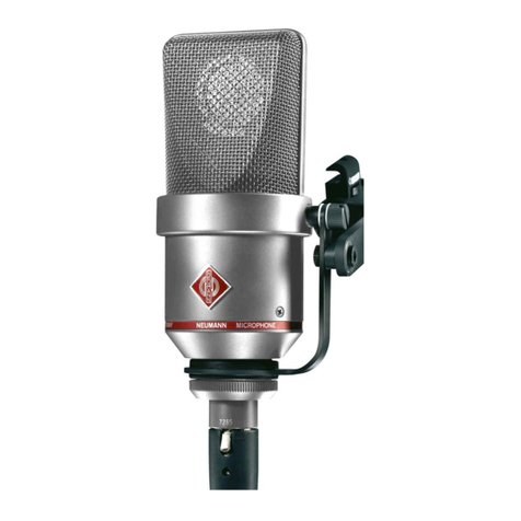
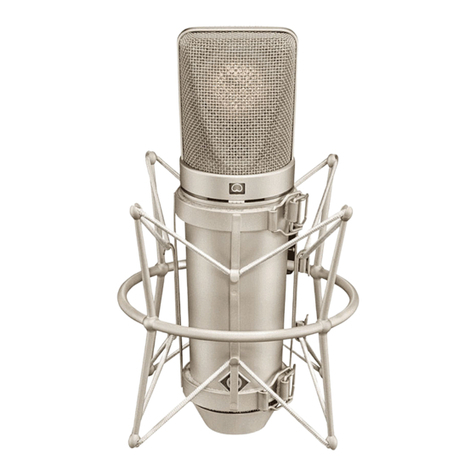
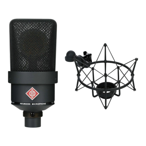
TLM 193
p us a thread adapter to connect to 1/2"- and 3/8"
stands. Ø 5 mm, ength 10 m. XLR 3 connectors.
AC 22 (0.3 m) ......................... Cat. No. 06598
Adapter cab e with XLR 5 M connector and unba -
anced 3.5 mm stereo jack. It is used to connect the
5-pin XLR output of the BS 48 i-2 power supp y or
the MTX 191 A matrix amp ifier to units with a
3.5 mm stereo input. It is designed for a micro-
phones of the fet 80/100 series and KM 100 F, ex-
c uding the KM 100 and the GFM 132.
AC 25 (0.3 m) ......................... Cat. No. 06600
Adapter cab e with XLR 3 M connector and unba -
anced 6.3 mm mono jack. It is used to connect
3-pin XLR outputs of power supp ies to units with
a 6.3 mm monojack input. Designed for a micro-
phones, exc uding KM 100 System and GFM 132.
AC 27 (0.3 m) ......................... Cat. No. 06602
Y-cab e with XLR 5 M connector and two unba -
anced 6.3 mm mono jacks. It is used to connect
XLR 5 outputs of the BS 48 i-2 power supp y or the
MTX 191 A matrix amp ifier to units with 6.3 mm
monojack inputs. Designed for a microphones,
exc uding KM 100 System and GFM 132.
Specia cab e engths can be made to order.
The microphone is particu ar y insensitive to ca-
pacitive oading. As a resu t, even very ong ca-
b e runs do not cause either TIM or frequency dis-
tortion.
Further artic es are described in the “Accessories”
cata og.
3. Power Supply
3.1 Phantom Powering
The TLM 193 is phantom powered at 48 V (P48,
IEC 1938).
With phantom powering the dc from the positive
supp y termina is divided via two identica resis-
tors, one ha f of the dc f owing through each au-
dio (modu ation) conductor to the microphone, and
returning to the vo tage source via the cab e
shie d. Phantom powering provides a fu y com-
patib e connecting system, since no potentia dif-
ferences exist between the two audio conductors.
Studio out ets so powered wi therefore a so ac-
As the TLM 193's amp ifier is inear up to 20 Hz,
extreme y ow frequency signa s can be transmit-
ted without distortion as we . On the other hand
the microphone is therefore more sensitive to ow-
frequency noises as structure-borne or wind and
pop disturbances. For specific app ications it is
therefore recommendab e to use protective acces-
sories as the EA 1 (mt) e astic suspension, the
PS 15 or PS 20 a pop screens or the WS 89 wind-
screen (see section 7).
2.1 Microphone Versions and
Output Wiring
The fo owing versions of the TLM 193 microphone
are avai ab e:
TLM 193 ............. blk ............. Cat. No. 08381
Version with 3-pin XLR connector insert and matte
b ack finish. Requires XLR 3 F fema e connector.
Microphone wired as per IEC 60 268-12 or DIN EN
60 268-12:
Modu ation is connected to pins 2 and 3; the
shie d is connected to pin 1. A sudden sound pres-
sure rise in front of the front diaphragm causes a
positive vo tage to appear at pin 2.
2.2 Microphone Cables
The fo owing cab es are avai ab e for the
TLM 193 microphone:
IC 3 mt ................ blk ............. Cat. No. 06543
Microphone cab e with doub e twist (doub e he ix)
braiding as shie d. Ø 5 mm, ength 10 m. XLR 3
connectors, matte b ack.
IC 31 mt (5 m) .... blk ............. Cat. No. 06570
Microphone cab e with doub e twist (doub e he ix)
braiding as shie d. Texti e-braided to avoid friction-
a noise due to the hand ing of booms or p astic
eadings (for examp e in windscreens). Ø 4,5 mm,
ength 5 m. XLR 3 connectors, matte b ack.
IC 4 (10 m) ......... ni ............... Cat. No. 06547
IC 4 mt (10m) .... blk ............. Cat. No. 06557
Microphone cab e with rotatab e swive mount for
microphones with a thread, and doub e twist
braiding as shie d. It has a 5/8"-27 fema e thread,
sphärische Einf üsse und gegen Schmutz. Die Kap-
se ist zum Schutz gegen Körperscha übertragung
e astisch ge agert.
Da der Verstärker des TLM 193 bis 20 Hz inear
ver äuft, können auch extrem niederfrequente Si-
gna e unverfä scht übertragen werden. Anderer-
seits ist das Mikrophon dadurch empfind icher für
tieffrequente Störungen wie Körperscha oder
Pop- und Windgeräusche. Daher empfieh t sich
eventue die Verwendung der E astischen Aufhän-
gung EA 1 (mt), des Popschirms PS 15 oder PS 20 a
oder des Windschutzes WS 89 (siehe Kapite 7).
2.1 Ausführungsformen und Beschaltung des
Mikrophonausgangs
Das Mikrophon kann in fo genden Ausführungsfor-
men ge iefert werden:
TLM 193 ............. sw ............ Best.-Nr. 08381
Ausführung mit 3-po igem XLR-Steckverbinder und
schwarzmatter Oberf äche. Erforder iches Gegen-
stück: XLR 3 F.
Die Zuordnung der Mikrophonansch üsse ent-
spricht DIN EN 60 268-12 bzw. IEC 60 268-12:
Die Modu ationsadern iegen an Pin 2 und 3, die
Abschirmung an Pin 1. Bei einem Scha druckan-
stieg vor der vorderen Mikrophonmembran tritt an
Pin 2 eine positive Spannung auf.
2.2 Mikrophonkabel
Für das Mikrophon TLM 193 stehen fo gende Ka-
be zur Verfügung:
IC 3 mt ............... sw ............ Best.-Nr. 06543
Mikrophonkabe mit Doppe dra umspinnung a s
Abschirmung. Ø 5 mm, Länge 10 m. XLR 3 Steck-
verbinder, schwarzmatt.
IC 31 mt (5 m) ... sw ............ Best.-Nr. 06570
Mikrophonkabe mit Doppe dra umspinnung a s
Abschirmung. Texti umsponnen, zur Vermeidung
von Reibgeräuschen bei der Verwendung an Mi-
krophonange oder Windschutzkorb. Ø 4,5 mm,
Länge 5 m. XLR 3 Steckverbinder, schwarzmatt.
IC 4 (10 m) ........ ni ............. Best.-Nr. 06547
IC 4 mt (10 m) ... sw ............ Best.-Nr. 06557
Kabe mit dreh- und schwenkbarem Stativge enk
für Mikrophone mit Gewindeansch uss, mit Dop-
pe dra umspinnung a s Abschirmung. Der Gewin-
deansch uss hat 5/8"-27-Gang, mit Adapter für
1/2"- und 3/8"-Stative. Ø 5 mm, Länge 10 m. XLR 3-
Verbinder.
AC 22 (0,3 m) ...................... Best.-Nr. 06598
Adapterkabe mit XLR 5 F-Buchse und 3,5 mm Ste-
reok inkenstecker, unsymmetrisch, für den An-
sch uss des XLR 5-Ausganges des Speisegerätes
BS 48 i-2 oder der Matrixbox MTX 191 A an Gerä-
te mit 3,5 mm Stereok inkenbuchse. Für a e Mikro-
phone außer der Ausgangsstufe KM 100 und des
GFM 132.
AC 25 (0,3 m) ...................... Best.-Nr. 06600
Adapterkabe mit XLR 3 F-Buchse und 6,3 mm Mo-
nok inkenstecker, unsymmetrisch, für den An-
sch uss des 3-po igen XLR-Ausganges eines Spei-
segerätes an Geräte mit 6,3 mm Monok inken-
buchse. Für a e Mikrophone mit Ausnahme der
Ausgangsstufe KM 100 und des GFM 132.
AC 27 (0,3 m) ...................... Best.-Nr. 06602
Y-Kabe mit einer XLR 5 F-Buchse und zwei 6,3 mm
Monok inkensteckern, unsymmetrisch, für den An-
sch uss des XLR 5-Ausganges des Speisegerätes
BS 48 i-2 oder der Matrixbox MTX 191 A an Gerä-
te mit 6,3 mm Monok inkenbuchsen. Für a e Mi-
krophone mit Ausnahme von KM 100 und GFM 132.
Andere Kabe ängen sind auf Wunsch ieferbar.
Das Mikrophon ist besonders unempfind ich gegen
kapazitive Be astung. TIM- und Frequenzgangver-
zerrungen werden daher auch bei Verwendung
sehr anger Kabe nicht hervorgerufen.
Weitere Artike sind im Kata og „Zubehör“ be-
schrieben.
3. Stromversorgung
3.1 Phantomspeisung
Das TLM 193 wird mit 48 V phantomgespeist (P48,
IEC 1938).
Bei der Phantomspeisung f ießt der Speisestrom
vom positiven Po der Spannungsque e über die
e ektrische Mitte der beiden Modu ationsadern
zum Mikrophon. Er wird hierzu über zwei g eich-
große Widerstände beiden Tonadern g eichsinnig
zugeführt. Die Rück eitung des G eichstroms er-
fo gt über den Kabe schirm. Zwischen beiden Mo-
du ationsadern besteht a so keine Potentia diffe-
renz. Daher ist mit der Phantomspeisung eine kom-


