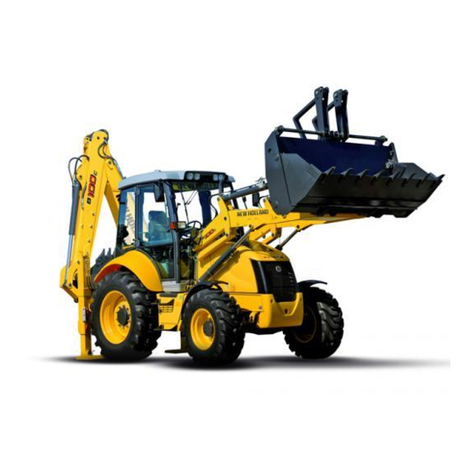
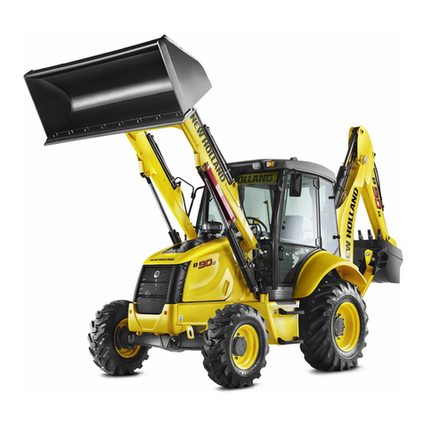
New Holland B90B User manual

Part number 87643850C
1st edition English
March 2011
SERVICE MANUAL
B90B / B95B / B95BLR /
B95BTC / B110B / B115B
Backhoe Loader
Printed!in!U.S.A.
Copyright © 2011 CNH America LLC. All Rights Reserved. New!Holland!is!a!registered!trademark!of!CNH America LLC.
Racine Wisconsin 53404 U.S.A.

SECTION 00 - SAFETY RULES 3
SAFETY INSTRUCTIONS
The non-compliance with the warnings preceded by
the above-mentioned keywords (WARNING and
DANGER) can cause serious accidents or even the
death of the persons involved.
Moreover, in the present Manual, some instructions
are given with text in italics, preceded by the words
NOTE and CAUTION.
NOTA: it emphasizes and underlines to the operator
the correct technique or correct procedure to follow.
SWARNING S
This warning symbol points out important mes-
sages involving your safety.
Carefully read the safety rules contained herein
and follow advised precautions to avoid potential
hazards and to safeguard your safety and personal
integrity.
In this manual you will find this symbol together
with the following keywords:
SWARNING S
This symbol warns about the possibility of potential
damages to the machine that can involve the oper-
ator’s safety.
SWARNING S
With specific warnings about potential dangers for
the operator’s or other persons integrity directly or
indirectly involved.
SWARNING S
This symbol warns about the possibility of potential
damages to the machine that can involve the oper-
ator’s safety.
Find manuals at https://best-manuals.com

4 SECTION 00 - SAFETY RULES
FOREWORD
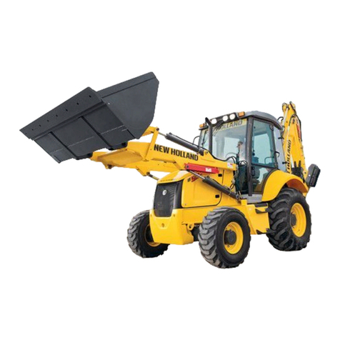
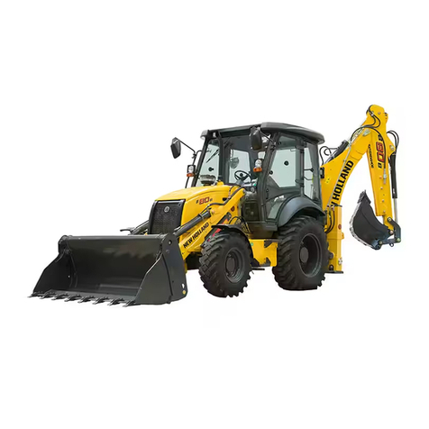
Loader backhoes B90B - B95B - B95BLR - B95BTC
- B110B - B115B have been designed to perform
most earth-moving operations.
If you use this machine for duties involving the use
of attachments, accessories, or special tools, con-
sult your Dealer to make sure that the adaptations or
modifications carried out are in conformity with the
machine’s technical specifications and with current
regulations on safety.
Any modifications or adaptations which are not
approved by the manufacturer may invalidate the
machine’s original conformity with safety require-
ments.
The machine must be used according to its
intended use, respecting the safety and precaution-
ary rules and strictly following the operating instruc-
tions. Any functional disorders, especially those
affecting the safety of the machine, should there-
fore be rectified immediately.
The manufacturer/supplier cannot be held respon-
sible for any damage resulting from unintended
use. The risk involved in such misuse lies entirely
with the user.
1
SDANGER S
A different use of the excavator or of its working
equipment:
- for lifting or transporting persons;
- as a working platform;
- for lifting loads without the attachment being
approved for this purpose;
- for pulling loads;
is considered unintended use.
Unintended use may cause injury or life-threatening
risks for the operator and for other persons.
SDANGER S
It is absolutely forbidden to tamper with and/or
change the setting of any of the hydraulic system
valves to avoid damaging machine components,
with a consequent risk for personal safety.
Find manuals at https://best-manuals.com

SECTION 00 - SAFETY RULES 5
The current Operator’s Manual is the user’s guide
for correct run-in, use and maintenance of the
machine.
Carefully read this Operator’s Manual and store it in
the cab for quick location and reference.
Instructions concerning safety, operation and main-
tenance have been developed to permit safe serv-
ice and operation of this machine.
In the event of queries or suggestions relevant to
your machine do not hesitate to address to your
Dealer. Dealers have qualified and trained person-
nel at disposal as well as Original Spares, means
and equipment suitable to carry out all necessary
maintenance.
Do not use this machine for any applications or pur-
poses other than those described in this manual. If
you use this machine for duties involving the use of
attachments, accessories, or special tools, consult
your Dealer to make sure that the adaptations or
modifications carried out are in conformity with the
machine’s technical specifications and with current
regulations on safety.
Any modifications or adaptations which are not
approved by the manufacturer may invalidate the
machine’s original conformity with safety require-
ments.
IMPORTANT: the engine and fuel system on your
machine are designed and built to government
emissions standards. Tampering by dealers, cus-
tomers, operators and users is strictly prohibited by
law. Failure to comply with this prohibition could
result in government fines, rework charges, invalid
warranty, legal action and possible confiscation of
the machine until rework to original condition is
completed. Engine service and/or repairs must be
carried out by a certified technician only.
NOTA: each machine is supplied complete with a
copy of this Manual. Descriptions and illustrations
provided herein are not binding. The Manufacturer,
provided that the basic characteristics of machine
types described and shown in this Manual remain
the same, reserves the right to change compo-
nents, parts and accessories supplied without any
commitment to timely update this publication; and
this any time it deems it convenient for improve-
ment purposes or due to commercial or manufac-
turing requirements. For exact information, please
consult your Dealer or contact the Manufacturer’s
Branch Offices, who remain at your disposal for fur-
ther help.
SPARE PARTS
The “non-genuine” spare parts have not been
checked and authorized by the Manufacturer. The
assembly and/or use of such products may have
negative effects on the machine design features
and could impair its operation safety. The Manufac-
turer is not liable for any damage caused by “non-
genuine” spare parts or accessories.
WARRANTY
This machine is under warranty according to the
regulations in force in Your Country and in compli-
ance with the sales agreement drawn up with the
Dealer. The warranty, however, expires if the opera-
tion and maintenance instruction for this machine
and contained in this manual, have not been fol-
lowed.
Find manuals at https://best-manuals.com
6 SECTION 00 - SAFETY RULES
SAFETY INSTRUCTIONS
Carefully read the safety rules contained herein and
follow advised precautions to avoid potential haz-
ards and to safeguard your safety and personal
integrity.
Your safety and that of the people around you
depends on you.
It is essential that you understand this manual for a
correct inspection, lubrication and repair of this
machine.
Read this manual carefully and check that:
- you understand fully the symbols on the controls
and the safety signs used in this manual and on
the machine;
- you understand fully the speed, stability, braking
and steering characteristics of the machine. If you
are in any doubt, consult your Dealer.
The safety messages in this section concern situa-
tions which may arise during normal machine opera-
tion, servicing and repair. These safety messages
also indicate the different ways of coping with these
situations. Other safety messages are used
throughout the manual to indicate specific dangers.
The information given in this chapter is a summary
of the basic rules to respect at all times and does
not exempt you from observing traffic regulations or
the requirements of insurance companies.
The presence of grease, oil, mud or (in winter) ice
on the steps and access handles can cause acci-
dents. Make sure they are always clean.
When mounting or dismounting from the machine
always face the machine and use the steps and
access handles on the left-hand side of the
machine.
Find manuals at https://best-manuals.com
SECTION 00 - SAFETY RULES 7
Wear close fitting clothing and safety equipment
appropriate for the job:
- safety helmet;
- safety shoes;
- heavy gloves;
- reflective clothing;
- wet weather clothing.
If the environment conditions make it necessary, the
following personal safety equipment should be at
hand:
- respirators (or dustproof masks);
- ear plugs or acoustic ears protections;
- goggles with lateral shield or masks for eyes pro-
tection.
Do not wear rings, wristwatches, jewels, unbuttoned
or flapping clothing such as ties, torn clothes,
scarves, open jackets or shirts with open zips which
could get caught into moving parts.
Do not use this machine for any applications or pur-
poses other than those described in this manual.
If you use this machine for duties involving the use
of attachments, accessories, or special tools, con-
sult your Dealer to make sure that the adaptations
or modifications carried out are in conformity with
the machine’s technical specifications and with cur-
rent regulations on safety.
Any modifications or adaptations which are not
approved by the manufacturer may invalidate the
machine’s original conformity with safety require-
ments.
Any functional disorders, especially those affecting
the safety of the machine, should therefore be recti-
fied immediately.
Make sure that you fully understand the symbols of
the safety decals applied on the machine. Make
sure that they are always clean and perfectly legi-
ble.
Be prepared for emergencies.
Always keep a first aid kit and a fire extinguisher
close at hand on the machine.
Make sure that the fire extinguisher is serviced in
accordance with the manufacturer’s instructions.
Find manuals at https://best-manuals.com
8 SECTION 00 - SAFETY RULES
PREVENTION OF FIRE OR EXPLOSIONS
The engine fuel can originate an explosion or a fire.
Never refuel when the engine is running.
Do not smoke during refuelling.
Take all the necessary safety measures when weld-
ing, grinding or when working near a naked flame.
Use a non-inflammable product for cleaning parts.
A spark or a flame can cause the electrolyte of the
battery to explode.
To prevent any risk of explosion, observe the follow-
ing instructions:
- when disconnecting the battery cables, always
disconnect the negative (-) cable first;
- to reconnect the battery cables, always connect
the negative (-) cable last;
- never short-circuit the battery clamps with metal
objects;
- do not weld, grind or smoke near a battery.
The engine exhaust may produce sparks.
Before using the machine in an area which may con-
tain inflammable vapours, ensure that there is good
ventilation.
Always keep a fire extinguisher available on the ma-
chine.
Make sure that it is properly maintained in conformity
with the manufacturer’s instructions.
Find manuals at https://best-manuals.com
SECTION 00 - SAFETY RULES 9
PREVENTION OF BURNS
The battery electrolyte generates severe burns.
The battery contains sulphuric acid.
Avoid any contact with the skin, eyes or clothing.
Antidote:
- EXTERNAL: rinse well with water, removing any
soiled clothing.
- INTERNAL: avoid vomiting. Drink water to rinse
your mouth. Consult a doctor.
- EYES: rinse thoroughly with water for 15 minutes
and get prompt medical attention.
When the electrolyte of a battery is frozen, it can
explode if you attempt to charge the battery or if you
try to start the engine using a booster battery.
Always keep the battery charged to prevent the elec-
trolyte freezing.
Batteries generate explosive gases.
Keep all flames, sparks and cigarettes away.
Provide good ventilation when changing a battery or
using a battery in an enclosed space.
Always protect your eyes when working near a bat-
tery.
Never touch the battery terminals with your hands.
This can induce a state of electrolysis and impair the
main organs of the body.
Hot coolant could spray out if the radiator cap is
removed while the system is still hot.
To remove the cap: allow the system to cool down,
turn the cap to the first notch and wait until there is
no more pressure.
Then remove the cap.
Find manuals at https://best-manuals.com
10 SECTION 00 - SAFETY RULES
PRECAUTIONS FOR WASTE DISPOSAL
Improperly disposing of waste can threaten the envi-
ronment.
Each country has its own Regulations on this sub-
ject. It is therefore advisable to prepare suitable con-
tainers to collect and store momentarily all solid and
fluid materials that must not be scattered in the envi-
ronment to avoid pollution.
At preset intervals these products will be delivered
to disposal stations legally recognized and present
in this Country.
Here below is a list of the products in the machine
which require disposal:
- hydraulic oil;
- brake system oil;
- coolant mixture, condensation residue and pure
anti-freeze;
- diesel oil;
- oil and diesel oil filter elements;
- engine and air conditioning air filter elements;
-battery.
Also polluting rags, paper, sawdust and gloves must
be disposed in compliance with the same proce-
dures.
Do not use food or beverage containers that may
mislead someone into drinking from them.
Do not pour waste onto the ground, down a drain, or
into any water source.
Air conditioning coolant escaping into the air can
damage the Earth’s atmosphere.
Government regulations may require a certified air
conditioning service centre to recover and recycle
used air conditioning coolant.
Obtain information on the proper way to recycle or
dispose of waste from your local environmental or
recycling centre, or from your Dealer.

B90B
B95B - B95BLR - B95BTC
B110B
B115B
SECTION 01 - MAINTENANCE

2 SECTION 01 - MAINTENANCE

SECTION 01 - MAINTENANCE 3
Do not carry out any service operation until you
have read and understood the instructions and
warnings given in this manual.
Observe the adjusting, maintenance and inspection
activities and intervals set out in the operating
instructions, including information on the replace-
ment of parts and equipment as this service con-
cerns exclusively the qualified personnel.
Wear safety equipment and suitable clothing to per-
form maintenance operations on the machine.
During maintenance operations, apply a warning
plate.
Always wear eye protection when using a tool which
might project metal particles. Use a hammer with a
soft face, such as copper, for pin assembly.
Incorrectly performed maintenance or adjustments
can cause serious injury. If you do not understand a
maintenance or adjustment procedure, consult your
Dealer.
Before performing any maintenance operation on
this machine, make sure it is in a safety condition.
Move the machine to a level and firm ground, away
from any soft ground, excavations and poorly
shored cavity.
Rest the loader attachment on the ground if no
maintenance operation is to be performed on it. Oth-
erwise, raise the attachment and block the support
strut.
Place the backhoe attachment in road travel posi-
tion if no maintenance operation is to be performed
on it. Otherwise, rest it on the ground.
Place the direction-of-travel lever and gearshift lever
in neutral position.
Immobilize the machine by means of the parking
brake.
Completely raise the stabilizers and lock them
mechanically.
Stop the engine and remove the starter key.
Open the oil tank plug.
Release the hydraulic pressure by operating the
control levers in all directions. On hydraulically con-
trolled machines, turn the key to ON and release the
pressure by moving the hydraulic control levers in
all directions.
Disconnect the electric system by disconnecting the
battery master switch.

4 SECTION 01 - MAINTENANCE
Place some wedges under the wheels so as to pre-
vent the machine from moving.
Unauthorized modifications of the machine can
cause serious injuries. Do not carry out any modifi-
cation on this machine without obtaining prior
authorization from your Dealer. Any modification
carried out must be in conformity with the machine’s
technical specifications and must conform to current
safety regulations.
Do not carry out any welding operation on the
machine without prior authorization from your
Dealer.
Some of the machine’s components are subject to
type approvals. It is mandatory when replacing
those components to ensure that they are in con-
formity with regulations.
Hydraulic fluid or grease under pressure which pen-
etrates the skin can cause serious injury. Take the
necessary safety precautions (protective clothing
and face and hand protection) to prevent all such
risks. In addition, before handling these products,
read the manufacturer’s specific instructions for
their use. If hydraulic fluid penetrates the skin a doc-
tor must be called immediately.
When carrying out a welding operation on the
machine, as authorized by the manufacturer and in
accordance with his specifications, disconnect the
electric system by means of the battery master
switch, connect the welding set earth lead to the
component on which the welding is to be carried out
(never connect the ground lead to a hydraulic sys-
tem component) and disconnect the electric cables
of the motor control unit (in case of electronic
motors).
A burst tyre can cause serious injury.
Regularly check the condition of tyres and always
observe the inflation pressures defined in accord-
ance with the type of tyre and ground conditions.
When checking the tyre pressure or during an infla-
tion operation, never stay in front of the tyre but
always keep to the tread side.
Always use an inflation cage when the wheel is
removed from the machine.
Keep all other persons away from the area.
Never weld near a tyre. It is essential to remove the
tyre before any welding operation.
Take the necessary safety measures to protect your
face when using compressed air.
The machine’s structure is in conformity with the
FOPS and ROPS protection standards.
Any modification (drilling, welding, etc.) may cause
that conformity to be invalidated.

SECTION 01 - MAINTENANCE 5
O-RING FLAT FACE SEAL FITTING
MINIMUM HARDWARE TIGHTENING TORQUES lfb·ft (Nm)
NOTA: there is no note on the page that * indicates lb·in and not lb·ft.
O-RING FLAT SEAL FITTING TORQUE VALUES
Nominal Dash size Thread size
(inch)
Swivel nut torque
O.D. (inch) Tube (mm) lbf·ft Nm
0.250
0.375
0.500
0.625
0.750
0.875
1.000
1.250
1.500
6.35
9.52
12.70
15.88
19.05
22.22
25.40
31.75
38.10
-4
-6
-8
-10
-12
-14
-16
-20
-24
9/16-18
11/16-16
13/16-16
1-14
1 3/16-12
1 3/16-12
1 7/16-12
1 11/16-12
2-12
12
18
37
51
75
75
105
140
160
16
24
50
69
102
102
142
190
217
INCH HARDWARE AND LOCKNUTS
SAE GRADE 2 SAE GRADE 5 SAE GRADE 8 LOCKNUTS
Nominal
Size
Unplated
or plated
silver
Plated
with zinc-
chrome
gold
Unplated
or plated
silver
Plated
with zinc-
chrome
gold
Unplated
or plated
silver
Plated
with zinc-
chrome
gold
Gr.B with
Grade 5
bolt
Gr.C with
Grade 8
bolt
Nominal
Size
1/4 55* (6.2) 72* (8.1) 86* (9.7) 112* (13) 121* (14) 157* (18) 61* (6.9) 86* (9.8) 1/4
5/16 115* (13) 149* (17) 178* (20) 229* (26) 250* (28) 324* (37) 125* (14) 176* (20) 5/16
3/8 17 (23) 22 (30) 26 (35) 34 (46) 37 (50) 48 (65) 19 (26) 26 (35) 3/8
7/16 27 (37) 35 (47) 42 (57) 54 (73) 59 (80) 77 (104) 30 (41) 42 (57) 7/16
1/2 42 (57) 54 (73) 64 (87) 83 (113) 91 (123) 117 (159) 45 (61) 64 (88) 1/2
9/6 60 (81) 77 (104) 92 (125) 120 (163) 130 (176) 169 (229) 65 (88) 92 (125) 9/16
5/8 83 (112) 107 (145) 128 (174) 165 (224) 180 (244) 233 (316) 90 (122) 127 (172) 5/8
3/4 146 (198) 189 (256) 226 (306) 293 (397) 319 (432) 413 (560) 160 (217) 226 (306) 3/4
7/8 142 (193) 183 (248) 365 (495) 473 (641) 515 (698) 667 (904) 258 (350) 364 (494) 7/8
1 213 (289) 275 (373) 547 (742) 708 (960) 773 (1048) 1000 (1356) 386 (523) 545 (739) 1
METRIC HARDWARE AND LOCKNUTS
CLASS 5.8 CLASS 8.8 CLASS 10.9 LOCKNUT
CL.8 with
Class 8.8
bolt
Nominal
Size
Unplated Plated with
zinc-chrome
Unplated Plated with
zinc-chrome
Unplated Plated with
zinc-chrome
M4 15* (1.7) 19* (2.2) 23* (2.6) 30* (3.4) 33* (3.7) 42* (4.8) 16* (1.8)
M6 51* (5.8) 67* (7.6) 79* (8.9) 102* (12) 115* (13) 150* (17) 56* (6.3)
M8 124* (14) 159* (18) 195* (22) 248* (28) 274* (31) 354* (40) 133* (15)
M10 21 (28) 27 (36) 32 (43) 41 (56) 45 (61) 58 (79) 22 (30)
M12 36 (49) 46 (63) 55 (75) 72 (97) 79 (107) 102 (138) 39 (53)
M16 89 (121) 117 (158) 137 (186) 177 (240) 196 (266) 254 (344) 97 (131)
M20 175 (237) 226 (307) 277 (375) 358 (485) 383 (519) 495 (671) 195 (265)
M24 303 (411) 392 (531) 478 (648) 619 (839) 662 (897) 855 (1160) 388 (458)

6 SECTION 01 - MAINTENANCE
SEALANTS
Description PN CNH Typical Applications
THREAD LOCK
AND SEAL 24 ml 82995773
General locking and sealing of metallic threads-medium
strength.
Oil tolerant.
Resists vibration, seals against corrosion and leakage.
Can be dismantled with standard tools.
SUPER GLUE
GEL 20 gm 82995778
General purpose instant non drip gel adhesive Ideal for
repair of cab trim, mats, external trim etc.
Bonds most materials including wood, rubber, metals,
most plastics.
Not absorbed by porous materials.
FLEXIBLE
GASKET
SEALANT 50 ml
82995770
Replaces pre-cut gasket materials.
Use on hydraulic lift cover joint, transmission to axle joint
and all rigid machined faces.
Anaerobic sealant cures on assembly.
Will not cure and block oil ways etc.
THREAD SEAL
50 ml 82995768
General purpose metallic thread and pipe sealant.
Use on fuel system, hydraulics, air lines etc.
Replaces pastes, hemp, pipe tape etc.
CLEAR
ADHESIVE 50 ml
AND SEALANT
310 ml
82995775
82995776
Clear, flexible adhesive and sealant.
Suitable for glass, metal, wood etc., seals and bonds
gaps to 6 mm (0.24 in).
Use to seal glazing and windshields, vehicle lamps,
electrical boxes, sump joints etc.
GASKET
DRESSING 60 ml 82995774
Non hardening sealant-enhances sealing of all types of
pre cut gaskets.
Holds gasket in place-assists assembly.
Dries slowly, sets to pliable film for easy dismantling.
STUD AND
BEARING LOCK
24 ml
82995772
General high strength metallic locking and sealing of all
threaded fasteners and studs.
Retains cylindrical parts, e.g. bushes, bearings, gears to
shafts etc.
Resists severe vibration loosening. Seals against
corrosion
SOLVENT
CLEANER AND
DEGREASER
400 ml
82995779
All purpose cleaner and degreaser.
Specially designed for parts to be lubricated, bonded or
sealed leaving no film or residue.
Removes grease, oil and dirt from electrical parts, tools
etc.

SECTION 01 - MAINTENANCE 7
MISCELLANEOUS
Description PN CNH Typical Applications
GASKET
REMOVER 300 ml 82995782
Spray on fast action foaming gasket remover.
Removes old heat hardened gasket residue without
damaging metal surfaces.
Removes all Loctite gaskets and gasket residue.
Removes carbon deposits from cylinder heads etc.
CITRUS HAND
CLEANER 400 ml
3 litre (0.79 gal)
82995780
82995781
Natural hand cleaner made from citrus oil.
Removes ground in dirt, grease, grime, paint, glue oil
and tar.
Contains premium skin conditioners.
Use with or without water.

8 SECTION 01 - MAINTENANCE
NOTES:

B90B
B95B - B95BLR - B95BTC
B110B
B115B
MODELS........................................................................................................................................................... 3
IDENTIFICATION OF MAIN COMPONENTS................................................................................................... 4
TECHNICAL SPECIFICATIONS....................................................................................................................... 5
DIESEL ENGINE ......................................................................................................................................... 5
TRANSMISSION.......................................................................................................................................... 8
AXLES ......................................................................................................................................................... 9
BRAKES .................................................................................................................................................... 10
STEERING................................................................................................................................................. 10
HYDRAULIC SYSTEM .............................................................................................................................. 11
FRONT COUNTERWEIGHT ..................................................................................................................... 11
NOISE AND VIBRATION LEVELS ............................................................................................................ 12
BUCKETS.................................................................................................................................................. 12
TYRES....................................................................................................................................................... 13
DIMENSIONS AND PERFORMANCE............................................................................................................ 14
DIMENSIONS - 2WS ................................................................................................................................. 14
DIMENSIONS - 4WS ................................................................................................................................. 16
LOADER ATTACHMENT PERFORMANCE.............................................................................................. 17
PERFORMANCE OF LOADER ATTACHMENT WITH FORKS ................................................................ 29
BACKHOE ATTACHMENT PERFORMANCE........................................................................................... 33
BACKHOE ATTACHMENT LIFTING CAPACITY ........................................................................................... 54
SUPPLY SUMMARY TABLE .......................................................................................................................... 58
SECTION 02 - TECHNICAL
SPECIFICATIONS
This manual suits for next models
5
Table of contents
Other New Holland Front End Loader manuals

New Holland
New Holland LS160 Instruction manual

New Holland
New Holland C227 User manual

New Holland
New Holland B90BLR User manual

New Holland
New Holland B110 Operating instructions

New Holland
New Holland B80B User manual

New Holland
New Holland B100C User manual

New Holland
New Holland L865 Operating instructions

New Holland
New Holland B95CTC User manual

New Holland
New Holland LB75.B User manual

New Holland
New Holland 611TL User manual