manuals.online logo
Brands
  1. Home
  2. •
  3. Brands
  4. •
  5. New Holland
  6. •
  7. Tractor
  8. •
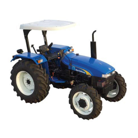
  9. New Holland TK65 User manual

New Holland TK65 User manual

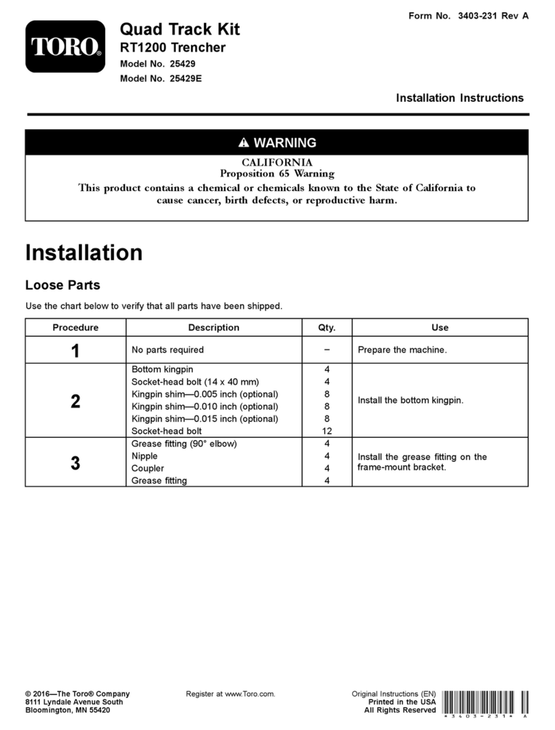
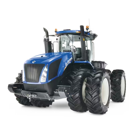
TK65 -- TK75 -- TK76 -- TK85 -- TK95
TRACTORS
SERVICE MANUAL
SECTIONS
GENERAL GUIDELINES 00........................................
ENGINE 10......................................................
CLUTCH 18......................................................
TRANSMISSIONS 21..............................................
REAR MECHANICAL TRANSMISSION 27...........................
POWER TAKE- OFF 31............................................
BRAKES 33......................................................
HYDRAULIC SYSTEMS 35........................................
STEERING CLUTCHES 46.........................................
SUSPENSION AND TRACKS 48...................................
ELECTRICAL SYSTEM 55.........................................
SERVICE
6035438100
Find manuals at https://best-manuals.com
SECTION 00 -- GENERAL -- CHAPTER 1 1
603.54.381.00 -- 05 -- 2001
GENERAL INSTRUCTIONS
IMPORTANT NOTICE
All maintenance and repair work described in this manual must be performed exclusively by NEW HOLLAND
service technicians, in strict accordance with the instructions given and using any specific tools necessary.
Anyone performing the operations described herein without strictly following the instructions is personally re-
sponsible for any eventual injury or damage to property.
BATTERY
Before carrying out any kind of service operations, disconnect and isolate the battery negative lead, unless other-
wise requested for specific operations (e.g.: operations that require the engine running). Once the specific oper-
ation has been completed, disconnect the lead in order to complete the operation.
SHIMMING
For each adjustment operation, select adjusting shims and measure individually using a micrometer, then add
up the recorder values. Do not rely on measuring the entire shimming set, which may be incorrect, or the rated
value indicated for each on shim.
ROTATING SHAFT SEALS
For correct rotating shaft seal installation, proceed as follows:
-- before assembly, allow the seal to soak in the oil it will be sealing for at least thirty minutes;
-- thoroughly clean the shaft and check that the working surface on the shaft is not damaged;
-- position the sealing lip facing the fluid; with hydrodynamic lips, take into consideration the shaft rotation direc-
tion and position the grooves so that they will deviate the fluid towards the inner side of the seal;
-- coat the sealing lip with a thin layer of lubricant (use oil rather than grease) and fill the gap between the sealing
lip and the dust lip on double lip seals with grease;
-- insert the seal in its seat and press down using a flat punch; do not tap the seal with a hammer or mallet;
-- whilst inserting the seal, check that the it is perpendicular to the seat; once settled, make sure that it makes
contact with the thrust element, if required;
-- to prevent damaging the seal lip on the shaft, position a protective guard during installation operations.
O--RING “SEALS”
Lubricate the O--RING seals before inserting them in the seats, this will prevent them from overturning and twist-
ing, which would jeopardise sealing efficiency.
SEALING COMPOUNDS
Apply one of the following sealing compounds on the mating surfaces marked with an X: RTV SILMATE, RHO-
DORSIL CAF 1 or LOCTITE 510 or SILASTIC AP black.
Before applying the sealing compound, prepare the surfaces as follows:
-- remove any incrustations using a wire brush;
-- thoroughly de--grease the surfaces using one of the following cleaning agents: trichlorethylene, petrol or a
water and soda solution.
BEARINGS
When installing bearings it is advised to:
-- heat the bearings to 80 to 90 0C (176 to 194 0F) before fitting on the shafts;
-- allow the bearings to cool before installing them from the outside.
SPRING PINS
When fitting split socket elastic pins, ensure that the pin notch is positioned in the direction of the force required
to stress the pin.
Spiral spring pins do not require special positioning.
Find manuals at https://best-manuals.com
2SECTION 00 -- GENERAL -- CHAPTER 1
603.54.381.00 -- 05 -- 2001
FRONT SEALS
Carefully check the metal rings, making sure that the
sealing surfaces show no signs of scoring, dents or
wear caused by ring pair misalignment or surface
flatness errors.
Even if only one of the rings is faulty, change the en-
tire seal.
Never pair a used ring with a new one or use different
pairs of rings.
To fit the seals, proceed as follows.
1. Eliminate any sharp edges or burr and carefully
clean the seats for the rubber rings.
2. Thoroughly clean the rings on the seals.
3. Insert each metal ring (2) on the respective
rubber ring (1), as shown in the drawing, acting
on the points indicated by the arrows.
1
4. Make sure that the metal ring is fitted correctly,
checking that measurement (A) is constant on all
of the circumference.
5. Assemble each pair of rings in their respective
seats (1), manually positioning the rubber ring
(as shown in figure
2
6. Before terminating assembly operations, clean
the sealing surfaces (1) with a clean (not frayed)
cloth and pour a thin covering of fluid oil over the
surfaces.
3
Find manuals at https://best-manuals.com
SECTION 00 -- GENERAL -- CHAPTER 1 3
603.54.381.00 -- 05 -- 2001
SPARE PARTS
Only use original NEW HOLLAND spare parts bearing the logo shown below.
4
Only original spare parts guarantee the same quality, duration and safety as they are the same parts that are
assembled during production.
Only original NEW HOLLAND parts can offer this guarantee.
When ordering spare parts, always provide the following information:
-- vehicle model (commercial name) and frame number;
-- engine type and number;
-- part number of the ordered part, which can be found in the “Microfiches” or the “Spare Parts Catalogue”, used
for order processing.
TOOLS
The tools that NEW HOLLAND propose and illustrate in this manual are:
-- specifically researched and designed for use with NEW HOLLAND vehicles;
-- essential for reliable repair operations;
-- accurately built and rigorously tested so as to offer efficient and long--lasting operation.
By using these tools, repair personnel will benefit from:
-- operating in optimal technical conditions;
-- obtaining the best results;
-- saving time and effort;
-- working in safe conditions.
CAUTION
Wear limit values indicated for certain parts are recommended, but not binding. The terms “front”, “rear”, “right--
hand” and “left--hand” (when referred to different parts) are intended as seen from the driving position with the
vehicle in the normal direction of movement.
MOVING THE TRACTOR WITH THE BATTERY REMOVED
External power supply cables should only be connected to the respective positive and negative cable terminals,
using efficient clamps that guarantee adequate and secure contact.
Disconnect all services (lights, windshield wipers, etc.) before starting the vehicle.
If the vehicle electrical system requires checking, carry out operations with the power supply connected; once
checking is completed, disconnect all services and switch off the power supply before disconnecting the cables.
Find manuals at https://best-manuals.com
4SECTION 00 -- GENERAL -- CHAPTER 1
603.54.381.00 -- 05 -- 2001
SAFETY REGULATIONS
WARNING AND DANGER SYMBOL
This warning symbol points out important messages
concerning your safety.
Carefully read the following safety regulations and
observe advised precautions in order to avoid poten-
tial hazards and safeguard your health and safety.
In this manual the symbol is accompanied by the fol-
lowing key--words:
CAUTION -- Warnings concerning unsuitable repair
operations that may jeopardise the safety of Service
personnel.
DANGER Specific warnings concerning potential
hazards for operator safety or for other persons di-
rectly or indirectly involved.
ACCIDENT PREVENTION
Most accidents or injuries that occur in workshops
are the result of non--observance of simple and fun-
damental safety regulations. For this reason, IN
MOST CASES THESE ACCIDENTS CAN BE
AVOIDED by foreseeing possible causes and conse-
quently acting with the necessary caution and care.
Accidents may occur with all types of vehicles, re-
gardless of how well it was designed and built.
A careful and judicious service technician is the best
guarantee against accidents.
Precise observance of the most basic safety rule is
normally sufficient to avoid many serious accidents.
DANGER. Never carry out any cleaning, lubrication
or maintenance operations when the engine is run-
ning.
SAFETY REGULATIONS
GENERAL GUIDELINES
-- Carefully follow specified repair and mainten-
ance procedures.
-- Do not wear rings, wristwatches, jewellery, un-
buttoned or loose articles of clothing such as:
ties, torn clothing, scarves, open jackets or shirts
with open zips that may remain entangled in
moving parts. It is advised to wear approved
safety clothing, e.g.: non--slip footwear, gloves,
safety goggles, helmets, etc.
5
-- Do not carry out repair operations with someone
sitting in the driver’s seat, unless the person is a
trained technician who is assisting with the oper-
ation in question.
-- Do not operate the vehicle or use any of the im-
plements from different positions, other than the
driver’s seat.
-- Do not carry out operations on the vehicle with
the engine running, unless specifically indicated.
-- Stop the engine and check that the hydraulic cir-
cuits are pressure--free before removing caps,
covers, valves, etc.
-- All repair and maintenance operations must be
carried out using extreme care and attention.
-- Service steps and platforms used in the work-
shop or elsewhere should be built according to
standard accident prevention regulations.
-- Disconnect the batteries and label all controls to
indicate that the vehicle is being serviced. Any
parts that are to be raised must be locked in posi-
tion.
-- Do not check or fill fuel tanks, accumulator bat-
teries, nor use starting liquid when smoking or
near naked flames, as these fluids are inflam-
mable.
-- Brakes are inoperative when manually released
for repair or maintenance purposes. Use blocks
or similar devices to control the machine in these
conditions.
-- The fuel nozzle should always be in contact with
the filling aperture. Maintain this position until fill-
ing operations are completed in order to avoid
possible sparks caused by the accumulation of
static electricity.
Find manuals at https://best-manuals.com
SECTION 00 -- GENERAL -- CHAPTER 1 5
603.54.381.00 -- 05 -- 2001
-- Only use specified towing points for towing the
tractor. Connect parts carefully. Make sure that
all pins and/or locks are secured in position be-
fore applying traction. Never remain near the
towing bars, cables or chains that are operating
under load.
-- Transport vehicles that cannot be driven using a
trailer or a low--loading platform trolley, if avail-
able.
-- When loading or unloading the vehicle from the
trailer (or other means of transport), select a flat
area capable of sustaining the trailer or truck
wheels. Firmly secure the tractor to the truck or
trailer and lock the wheels in the position used by
the carrier.
-- Electric heaters, battery--chargers and similar
equipment must only be powered by auxiliary
power supplies with efficient ground insulation to
avoid electrical shock hazards.
-- Always use suitable hoisting or lifting devices
when raising or moving heavy parts.
-- Take extra care if bystanders are present.
-- Never pour gasoline or diesel oil into open, wide
or low containers.
-- Never use gasoline, diesel oil or other inflam-
mable liquids as cleaning agents. Use non--in-
flammable, non toxic commercially available sol-
vents.
-- Wear safety goggles with side guards when
cleaning parts with compressed air.
-- Limit the air pressure to a maximum of 2.1 bar
(30.46 psi), according to local regulations.
-- Do not run the engine in confined spaces without
suitable ventilation.
-- Do not smoke, use naked flames, or cause
sparks in the area when fuel filling or handling
highly inflammable liquids.
-- Never use naked flames for lighting when work-
ing on the machine or checking for“leaks.
-- All movements must be carried out carefully
when working under, on or near the vehicle.
Wear protective equipment: helmets, goggles
and special footwear.
-- When carrying out checks with the engine run-
ning, request the assistance of an operator in the
driver’s seat. The operator must maintain visual
contact with the service technician at all times.
-- If operating outside the workshop, position the
vehicle on a flat surface and lock in position. If
working on a slope, lock the vehicle in position.
Move to a flat area as soon as is safely possible.
-- Damaged or bent chains or cables are unreliable.
Do not use them for lifting or towing. Always use
suitable protective gloves when handling chains
or cables.
-- Chains should always be safely secured. Make
sure that the hitch--up point is capable of sustain-
ing the load in question. Keep the area near the
hitch--up point, chains or cables free of all by-
standers.
-- Maintenance and repair operations must be car-
ried out in a CLEAN and DRY area. Eliminate any
water or oil spillage immediately.
-- Do not create piles of oil or grease--soaked rags
as they represent a serious fire hazard. Always
store rags in a closed metal container.
Before starting the vehicle or implements, make
sure that the driver’s seat is locked in position.
Also check that there are no persons within the
tractor or implement range of action.
-- Empty pockets of all objects that may fall unob-
served into the vehicle parts.
-- In the presence of protruding metal parts, use
protective goggles or goggles with side guards,
helmets, special footwear and gloves.
-- When welding, use protective safety devices:
tinted safety goggles, helmets, special overalls,
gloves and footwear. All persons present in the
area where welding is taking place must wear
tinted goggles. NEVER LOOK DIRECTLY AT
THE WELDING ARC WITHOUT SUITABLE
EYE PROTECTION.
-- Metal cables tend to fray with repeated use. Al-
ways use suitable protective devices (gloves,
goggles, etc.) when handling cables.
-- Handle all parts carefully. Do not put your hands
or fingers between moving parts. Wear suitable
safety clothing -- safety goggles, gloves and
shoes.
Find manuals at https://best-manuals.com
6SECTION 00 -- GENERAL -- CHAPTER 1
603.54.381.00 -- 05 -- 2001
START UP
-- Never run the engine in confined spaces that are
not equipped with adequate ventilation for ex-
haust gas extraction.
-- Never place the head, body, limbs, feet, hands or
fingers near fans or rotating belts.
ENGINE
-- Always loosen the radiator cap slowly before re-
moving it to allow any remaining pressure in the
system to be discharged. Filling up with coolant
should only be carried out with the engine
stopped or idling (if hot).
-- Never fill up with fuel when the engine is running,
especially if hot, in order to prevent the outbreak
of fire as a result of fuel spillage.
-- Never check or adjust fan belt tension when the
engine is running.
Never adjust the fuel injection pump when the ve-
hicle is moving.
-- Never lubricate the vehicle when the engine is
running.
ELECTRICAL SYSTEMS
-- If it is necessary to use auxiliary batteries, re-
member that both ends of the cables must be
connected as follows: (+) with (+) and (--) with (--).
Avoid short--circuiting the terminals. GAS RE-
LEASED FROM BATTERIES IS HIGHLY IN-
FLAMMABLE. During charging, leave the bat-
tery compartment uncovered to improve
ventilation. Never check the battery charge using
“jumpers” (metal objects placed on the ter-
minals). Avoid sparks or flames near the battery
zone. Do not smoke to prevent explosion haz-
ards.
-- Before servicing operations, check for fuel or
current leaks. Eliminate any eventual leaks be-
fore proceeding with work.
-- Never charge batteries in confined spaces. Make
sure that there is adequate ventilation in order to
prevent accidental explosion hazards as a result
of the accumulation of gases released during
charging operations.
-- Always disconnect the batteries before perform-
ing any kind of servicing on the electrical system.
HYDRAULIC SYSTEMS
-- A liquid leaking from a tiny hole may be almost
invisible but, at the same time, be powerful
enough to penetrate the skin; Therefore, NEVER
USE HANDS TO CHECK FOR LEAKS. Use a
piece of cardboard or wood for this purpose. If
any liquid penetrates skin tissue, call for medical
aid immediately. Failure to treat this condition
with correct medical procedure may result in seri-
ous infection or dermatosis.
-- In order to check the pressure in the system use
suitable instruments.
WHEELS AND TYRES
-- Make sure that the tyres are correctly inflated at
the pressure specified by the manufacturer.
Periodically check the rims and tyres for dam-
age.
-- Stand away from (at the side of) the tyre when
checking inflation pressure.
-- Only check pressure when the tractor is un-
loaded and the tyres are cold, to avoid incorrect
readings as a result of over--pressure. Do not use
parts of recovered wheels as incorrect welding
brazing or heating may weaken and eventually
cause damage to the wheel.
-- Never cut or weld a rim mounted with an inflated
tyre.
-- To remove the wheels, lock both the front and
rear vehicle wheels. After having raised the ve-
hicle, position supports underneath, according to
regulations in force.
-- Deflate the tyre before removing any objects that
may be jammed in the tyre tread.
-- Never inflate tyres using inflammable gases; as
this may result in explosions and injury to by-
standers.
REMOVAL AND RE--FITTING
-- Lift and handle all heavy parts using suitable ho-
isting equipment. Make sure that parts are sus-
tained by appropriate hooks and slings. Use the
hoisting eyebolts for lifting operations. Extra care
should be taken if persons are present near the
load to be lifted.
-- Handle all parts carefully. Do not put your hands
or fingers between parts. Wear suitable safety
clothing -- safety goggles, gloves and shoes.
-- Avoid twisting chains or metal cables. Always
wear safety gloves when handling cables or
chains.
Find manuals at https://best-manuals.com
SECTION 00 -- GENERAL -- CHAPTER 1 7
603.54.381.00 -- 05 -- 2001
CONSUMABLES
COMPONENT TO BE FILLED
OR TOPPED UP
QUANTITY
dm3
(gallons)
RECOMMENDED
NEW HOLLAND
PRODUCTS
NEW HOLLAND
SPECIFICATIONS
INTERNATIONAL
SPECIFICATIONS
Cooling system:
-- models TK65, TK75 ......
-- models TK76, TK85, TK95
10.5 (2.31)
13.0 (2.86)
Water & liquid
AMBRA
AGRIFLU
50% + 50%
NH 900 A --
Fuel tank:
-- models TK65, TK75 ......
-- models TK76, TK85, TK95
80 (17.6)
129 (28.38)
Decanted and fil-
tered diesel fuel -- --
Engine sump:
without filter:
-- models TK65, TK75 ......
-- models TK76, TK85, TK95
with filter:
-- models TK65, TK75 ......
-- models TK76, TK85, TK95
6.7 (1.47)
10.5 (2.31)
7.3 (1.61)
11.2 (2.46)
AMBRA
SUPER GOLD
15W -- 40 oil or
10W -- 30
NH 330G
(SAE 15W--40)
NH 24G
(SAE 10W--30)
API CF--4/SG
CCMC D4
MIL--L--2104E
Steeringclutches ............ 1.4 (0.31) AMBRA
SUPER oil 10W NH 301 C
API CE CCMC D4
MIL--L--2104C
SAE 10W
Transmission:
(gears, bevel drive,
brakes and hydraulic
lift)
-- models TK65, TK75 ......
-- models TK76, TK85, TK95
Track tension wheel,
carriage rollers, track support
rollers......................
33.3 (7.32)
39.0 (7.92)
--
AMBRA MULTI F
oil NH 420 A
API GL4
ISO 46/68
SAE 20W--30
Final drives
(each) ..................... 2.0 (0.44)
AMBRA
HYPOIDE 90 oil NH 520 A
API GL5
MIL--L--2105D
SAE 80W--90
Greasefittings .............. -- AMBRA GR9
grease
NH 710 A NLGI 2
Find manuals at https://best-manuals.com
8SECTION 00 -- GENERAL -- CHAPTER 1
603.54.381.00 -- 05 -- 2001
Find manuals at https://best-manuals.com
SECTION 10 -- ENGINE -- CHAPTER 1 1
603.54.381.00 -- 05 -- 2001
SECTION 10 -- ENGINE
Chapter 1 -- Engine
CONTENTS
Section Description Page
10 000 General specifications 2.........................................................
Main data 5....................................................................
Torque settings 24..............................................................
Tools 25.......................................................................
Sections 27....................................................................
Lubrication and cooling system diagrams 31........................................
Troubleshooting 34..............................................................
10 001 10 Engine. Removal--Installation 38..................................................
10 001 30 Engine. Compression test 42.....................................................
10 001 54 Engine. Disassembly--Assembly 43...............................................
10 101 53 Valve guides. Replacement 78....................................................
10 101 60 Injector sleeve. Replacement 82..................................................
10 102 70 Front engine oil seal. Removal--Installation 87......................................
10 106 12 Valve/rocker arm clearance 91....................................................
10 216 10 Rear fuel tank -- models TK 65 and TK 75. Removal--Installation 94....................
10 216 10 Rear fuel tank -- models TK 76, TK 85 and TK 95. Removal--Installation 97.............
10 216 40 Front fuel tank -- models TK 65 and TK 75. Removal--Installation 100..................
10 216 40 Front fuel tank -- models TK 76, TK 85 and TK 95. Removal--Installation 102............
10 218 30 Engine injectors. Removal--Installation 104.........................................
10 246 14 Bosch injection pump. Removal--Installation timing and air bleeding check 106..........
10 254 44 Exhaust pipe. Removal--Installation 113............................................
10 402 11 Coolant pump. Removal--Installation with radiator removed 114.......................
10 402 28 Coolant pump. Overhaul 115.....................................................
10 402 30 Thermostat. Removal--Installation 116.............................................
10 406 10 Radiator. Removal--Installation 117................................................
10 414 10 Coolant pump and generator drive belt. Adjustment 120..............................
2SECTION 10 -- ENGINE -- CHAPTER 1
603.54.381.00 -- 05 -- 2001
GENERAL SPECIFICATIONS 3 cylinders 4 cylinders
Engine, technical type:
-- model TK 65 -- type 8035.05.421 (BOSCH pump) ..... See data on page 6--7 --
-- model TK 75 -- type 8035.25.421 (BOSCH pump) ..... See data on page 8--9 --
-- model TK 76 -- type 8045.06.421/521 (BOSCH pump) . -- See data on page 10--11
-- model TK 85 -- type 8045.05.421/521 (BOSCH pump) . -- See data on page 12--13
-- model TK 95 -- type 8045.25L.421 (BOSCH pump) .... -- See data on page 14--15
Cycle ............................................... diesel, 4--stroke
Injection............................................. direct
Number of on--line cylinders ........................... 3 4
Cylinder liners ....................................... dry force--fitted in cylinder block
Piston diameter
-- models TK 65, TK 75 .............................. 104 mm (4.0945 in.) --
-- model TK 76 ..................................... -- 100 mm (3.937 in.)
-- models TK 85, TK 95 .............................. -- 104 mm (4.0945 in.)
Pistonstroke ........................................ 115 mm (4.37 in.)
Total displacement:
-- model TK 65 ..................................... 2931 cm3(0.6447 gal.) --
-- model TK 75 ..................................... 2931 cm3(0.6447 gal.) --
-- model TK 76 ..................................... -- 3613 cm3(0.7947 gal.)
-- model TK 85 ..................................... -- 3908 cm3(0.8596 gal.)
-- model TK 95 ..................................... -- 3908 cm3(0.8596 gal.)
Compression ratio for models TK 65, TK 76 and TK 85 .... 17 to 1 normally aspirated
Compression ratio for models TK 75 and TK 95 .......... 16.5 to 1 turbocharged
Maximum power:
-- model TK 65 ..................................... 44.5 kW (60 Hp) --
-- model TK 75 ..................................... 54 kW (72 Hp) --
-- model TK 76 ..................................... -- 53 kW (71 Hp)
-- model TK 85 ..................................... -- 58.8 kW (80 Hp)
-- model TK 95 ..................................... -- 66.5 kW (90 Hp)
Maximum power speed -- models TK 65, TK 75 .......... 2300 rpm
Maximum power speed -- TK 76, TK 85, TK 95 ........... 2500 rpm
Maximum torque speed -- model TK 65 .................. 1400 rpm --
Maximum torque speed -- model TK 75 .................. 1400 rpm --
Maximum torque speed -- model TK 76 .................. -- 1500 rpm
Maximum torque speed -- model TK 85 .................. -- 1500 rpm
Maximum torque speed -- model TK 95 ................. -- 1500 rpm
Number of main bearings .............................. 4 5
Sumppan ........................................... structural, cast iron
(continued)
SECTION 10 -- ENGINE -- CHAPTER 1 3
603.54.381.00 -- 05 -- 2001
(continued)
GENERAL SPECIFICATIONS 3 cylinders 4 cylinders
Lubrication system .................................... forced, with gear pump
Pumpdrive ............................................ camshaft
Engine speed/oil pump speed ratio ....................... 2:1
Oil cleaning ............................................ mesh filter on oil intake and filtering car-
tridge on delivery line
Normal oil pressure with motor warmed--up and running at
maximum speed:
For models TK 65, TK 76, TK 85 ......................... 2.9 to 3.9 bar (42.1 to 56.6 psi)
For models TK 75, TK 95 (starting pressure) .............. 6 bar (87 psi)
Pressurereliefvalve .................................... incorporated in oil pump housing
Valve initial opening pressure ............................ 3.5 bar (50.8 psi)
Forfurtherlubricationtechnicaldata ...................... See page 23
Cooling system ....................................... coolant circulation
Radiator on models TK 65, TK 75 ........................ 3 lines of vertical pipes with copper fins
Radiator on models TK 76, TK 85, TK 95 .................. 4 lines of vertical copper pipes
Fan,attachedtocoolantpumppulley ..................... intake, 4--blade in sheet--metal
Coolantpump .......................................... centrifugal vane--type
Engine speed/coolant pump speed ratio ................... 1:1.403
Temperaturecontrol .................................... thermostat
Coolantthermometer ................................... coloured scale divided into 3 sections
Temperature ranges corresponding to each section:
-- initialwhitesection .................................. 30 to 65 oC (86 to 149 oF)
-- middle green section (normal working conditions) ........ 65 to 105 oC (149 to 221 oF)
-- finalredsection ..................................... 105 to 115 oC (221 to 239 oF)
For further cooling system technical data .................. See page 23
Rev counter .......................................... incorporated in control panel
Operating system ...................................... from gear on camshaft
Hour counter calibrated for engine speed of ................ 1800 rpm
(continued)
4SECTION 10 -- ENGINE -- CHAPTER 1
603.54.381.00 -- 05 -- 2001
(continued)
GENERAL SPECIFICATIONS 3 cylinders 4 cylinders
Timing system ........................................ overhead valves operated by tappets, rods
and rocker arms via the camshaft located
in the engine block; the camshaft is driven
by the crankshaft using helical gears
Inlet:
-- start:beforeTDC. ................................... 12o
-- end: after BDC. ..................................... 31o
Exhaust:
-- start:beforeBDC.................................... 50o
-- end: after TDC. ..................................... 16o
valve--rockerarmclearancefortimingcheck ............... 0.45 mm (0.248 in.)
valve--rocker arm clearance (with engine cold):
-- intake ............................................. 0.30 ±0.05 mm (0.1654 ±0.0276 in.)
-- exhaust ............................................ 0.30 ±0.05 mm (0.1654 ±0.0276 in.)
For further timing system technical data ................... See page 20
Fuel system
Air cleaning ............................................ dual cartridge dry air filter, with clogged
filter indicator with centrifugal pre--filter
and automatic dust ejector
Fuelpump............................................. double diaphragm
Fuelfiltering ........................................... through wire filter in fuel supply pump, and
replaceable cartridge on delivery line to
injection pump
Minimum fuel flow rate with pump shaft rotating at 1600 rpm . 100 litres/hour (22 gal./hour)
Cam operated ......................................... engine timing
BOSCHinjectionpump.................................. rotating distributor type
All--speed governor, incorporated in pump:
BOSCH ............................................... centrifugal counterweights
Automatic advance regulator, incorporated in pump:
BOSCH ............................................... hydraulic
For further fuel system technical data:
Fixed advance (pump setting for start of delivery before TDC)
-- Pressure setting -- Injection order, and other information
regarding the BOSCH pump ............................. refer to the data for the relevant engine
type in the table on page 2
SECTION 10 -- ENGINE -- CHAPTER 1 5
603.54.381.00 -- 05 -- 2001
FUEL SYSTEM DATA
Turbocharger (models TK 75, TK 95):
-- GARRETTtype ..................................... TA 3118--0.82 A/R--57
Injectionpump ......................................... rotating distributor with speed governor
and advance variator incorporated
BOSCH pump:
-- model TK 65 ....................................... VE 3/11 F 1150 L 766 -- 99441586
-- model TK 75 ....................................... VE 3/11 F 1150 L 764 -- 99441587
-- model TK 76 ....................................... VE 4/11 F 1250 L 794 -- 99472104
-- model TK 76 ....................................... VE 4/11 F 1250 L 810 -- 500324959
-- model TK 85 ....................................... VE 4/11 F 1250 L 773 -- 99472102
-- model TK 85 ....................................... VE 4/11 F 1250 L 787 -- 500324962
-- model TK 95 ....................................... VE 4/11 F 1250 L 850 -- 500358111
Directionofrotation ..................................... counter--clockwise
Injectionorder ......................................... 1--2--3 (TK 65, TK 75) 1--3--4--2 (TK 76,
TK 85, TK 95)
TK 65 TK 75 TK 85 TK 95 TK 76
Injectors:
BOSCHtype....................... 500307714 500317389
-- Nozzleholdertype .............. 4791124 (KBEL83S35)
-- Nozzletype .................... 99469341 (DLLA132S1320) 500317390
(DLLA132S
1335)
Numberofnozzleholes ............. 5 5
Nozzle hole diameter mm (in.)...... 0.23 (0.0091) 0.21
(0.0083)
Calibration pressure bar (psi)....... 260 to 272 (3771 to 3945) 260 to 272
(3771 to
3945)
Delivery lines for BOSCH pump
-- type ........................... 99441952 -- 99449006 --
-- Line dimension mm (in.)........ 6x1.75x540
(0.2362x0.0689x21.260)
6x1.75x530
(0.2362x
0.0689x
20.866)
6x1.75x530
(0.2362x
0.0689x
20.866)
--
6SECTION 10 -- ENGINE -- CHAPTER 1
603.54.381.00 -- 05 -- 2001
MODEL TK 65 -- CALIBRATION DATA FOR BOSCH INJECTION PUMP
TYPE VE 3/11 F 1150 L 766 -- 99441586
ASSEMBLY DATA
Pump timing on engine: delivery start 9o±0.5obefore
TDC of cylinder 1 compression stroke.
Plunger pre--lift for timing on engine: 1 mm (0.0394
in.) from BDC (with tools 291754 -- 291755).
Cylinder No.1 delivery line union on pump: marked
with letter A.
ASSEMBLY DIMENSIONS
SYMBOL VHA MS ya yb
mm
(in.)
30.1
(1.185)
-- 36.5 to 38.5
(1.437 to
1.5157)
40.4 to 45.6
(1.5905 to
1.7953)
CALIBRATION TEST CONDITIONS
Test bench conforming to ISO 4008/1 .../2
Injectors conforming to ISO 7440--A61 --
(1.688.901.020 with calibrated pad Æ0.6 mm --
0.0236 in.).
Injector pressure setting 172 to 175 bar (2495 to
2538 psi).
Fuel supply pressure:
0.35 + 0.05 bar (5.1 + 0.7 psi).......
Pipes (conforming to ISO 4093.2):
6 x 2 x 840 mm (0.2362 x 0.0787 x 33.071 in.).......
Graduate drain time : 30”..........
Test liquid: ISO 4113 at a temperature of 45o±1oC
(113o±33.8oF) at outlet.
1. START OF DELIVERY
Plunger pre--lift from TDC:
mm --
Pump rotation (viewed from drive side):
counter--clockwise
Injection order:1--2--3
2. ADVANCE REGULATOR STROKE
rpm: 1220 Advance stroke: 0.7 to 1.1 mm (0.0276 to 0.0433 in.)
3. FUEL SUPPLY PUMP PRESSURE
rpm: 1220 Internal pressure: 7.9 to 8.5 bar (114.5 to 123.3 psi)
4. FULL LOAD DELIVERY
rpm: 700 Delivery per 1000 shots: 66.7 to 67.7 cm3(0.0147 to 0.0149 gal.) Spread: £3.5 cm3(0.0008 gal.)
5. SPREAD GOVERNOR AT IDLE SPEED
rpm: 325 Delivery per 1000 shots: 16.3 to 17.3 cm3(0.0036 to 0.0038 gal.) Spread: £5.5 cm3(0.0012 gal.)
6. SPREAD GOVERNOR AT MAXIMUM SPEED
rpm: 1200 Delivery per 1000 shots: 48.5 to 49.5 cm3(0.0107 to 0.0109 gal.) Spread: cm3--
7. DELIVERY AT STARTING SPEED
rpm: 100 Delivery per 1000 shots: 60 to 100 cm3(0.0132 to 0.022 gal.)
8. TRANSFER PRESSURE PROGRESSION
rpm 1220 400
Internal pressure bar (psi) 7.9 to 8.5 (114.6 to 123.3) 3.4 to 4.4 (49.3 to 63.8)
9. INJECTION ADVANCE PROGRESSION
rpm 1220 1260
Advance stroke mm (in.) 0.7 to 1.1 (0.276 to 0.0433) 1.3 to 1.9 (0.0512 to 0.0748)
10. BACKFLOW
rpm 400 1150
Backflow cm3(gal.)/10 sec 16 to 28 (0.0035 to 0.0062) 20 to 36 (0.0044 to 0.0079)
(continued)
Note: the values shown above in brackets must be used for checking purposes only.
SECTION 10 -- ENGINE -- CHAPTER 1 7
603.54.381.00 -- 05 -- 2001
(continued)
11. DELIVERY PROGRESSION
rpm Delivery per 1000 shots: cm3(gal.)
1270 0 to 3 (0 to 0.0007)
1200 48.5 to 49.5 (0.0107 to 0.0109)
700 66.7 to 67.7 (0.0147 to 0.0149)
1150 64.4 to 68.4 (0.0142 to 0.0150)
12. DELIVERY CHECK AT IDLE SPEED
rpm 325 275
Delivery per 1000 shots: cm3(gal.) 16.3 to 17.3 (0.0036 to 0.0038) 46 to 47 (0.0101 to 0.0103)
13. ZERO CAPACITY (STOP)
rpm Voltage (volts) Delivery per 1000 shots: cm3(gal.)
325 00 to 3 (0 to 0.0070)
14. AUTOMATIC START SUPPLEMENT
rpm Delivery per 1000 shots: cm3(gal.)
100 60 to 100 (0.0132 to 0.022)
270 59 to 69 (0.0130 to 0.0152)
Note: the values shown above in brackets must be used for checking purposes only.
BENCH TEST PERFORMANCE DATA
Test conditions
Fixed advance before TDC cylinder No.1 in compression
stroke: (see previous page)
Relative humidity 70o/o±5.
Engine without fan, air filter and exhaust silencer. Ambient temperature 20 ±3oC(68±37.4 oF).
Atmospheric pressure 740 ±5 mm (29.1339 ±0.1968 in.)
mercury.
Specific gravity of diesel fuel 840 g/l at a tem-
perature of 15 oC(59oF).
Throttle
l
B
k
i
l
d
l
i
d
Engine speed Power output with engine run--in for a total of: Fuel consum-
ption
lever
position
Braking load applied
rpm
Production speed
kW (Hp)
50 hours (total)
kW (Hp) kg (lbs.)/h
Maximum For maximum power
output 2300 ³42 (57.1) 43 to 45.6
(58.5 to 62)
9.9 to 10.5
(21.83 to
23.15)
Maximum For maximum torque 1400 ³29.4 (40) 30 to 31.8
(40.8 to 43.2)
6.4to6.8
(14.11 to
23.15)
Maximum None (no--load) 2450 to
2500 -- -- --
Minimum None (no--load) 625 to 675 -- -- --
8SECTION 10 -- ENGINE -- CHAPTER 1
603.54.381.00 -- 05 -- 2001
MODELS TK 75 -- CALIBRATION DATA FOR BOSCH INJECTION PUMP
TYPE VE 3/11 F 1150 L 764 -- 99441587
ASSEMBLY DATA
Pump timing on engine: delivery start 6o±0.5obe-
fore TDC of cylinder 1 compression stroke.
Plunger pre--lift for timing on engine: 1 mm
(0.0394 in.) from BDC (with tools 291754 -- 291755).
Cylinder No.1 delivery line union on pump: marked
with letter A.
ASSEMBLY DIMENSIONS
SYMBOL KMS ya yb
mm
(in.)
-- -- 38.6 to 40.6
(1.5197 to
1.5984)
40.4 to 45.6
(1.5905 to
1.7953)
CALIBRATION TEST CONDITIONS
Test bench conforming to ISO 4008/1 .../2
Injectors conforming to ISO 7440--A61 --
(1.688.901.027 with calibrated pad Æ0.5 mm --
0.0197 in.).
Injector pressure setting 250 to 253 bar (3626 to
3669 psi).
Fuel supply pressure:
0.35 + 0.05 bar (5.1 + 0.7 psi).......
Delivery pipes (conforming to ISO 4093.2):
6 x 2 x 450 mm (0.2362 x 0.0787 x 17.716 in.).......
Graduate drain time : 30”..........
Test liquid: ISO 4113 at a temperature of 45o±1oC
(113o±33.8oF) at outlet.
1. START OF DELIVERY
Plunger pre--lift from TDC:
mm --
Pump rotation (viewed from drive side):
counter--clockwise
Injection order:1--2--3
2. ADVANCE REGULATOR STROKE
rpm: 850 LDA pressure: kPa 100 Advance stroke: 0.2 to 1.2 mm (0.0079 to 0.0472 in.)
3. FUEL SUPPLY PUMP PRESSURE
rpm: 1220 LDA pressure: kPa 100 Internal pressure: 8.3 to 9.5 bar (129.1 to 137.8 psi)
4. FULL--LOAD DELIVERY WITH BOOSTER PRESSURE
rpm: 700 LDA pressure: kPa 100 Delivery per 1000 shots: 88.4 to 93.4 cm3(0.0194 to 0.0205 gal.) Spread: £-- c m 3
5. FULL--LOAD DELIVERY WITHOUT BOOSTER PRESSURE
rpm: 600 LDA pressure: kPa 0 Delivery per 1000 shots: 70.5 to 75.5 cm3(0.0155 to 0.0166 gal.) Spread: -- cm3
6. SPREAD GOVERNOR AT IDLE SPEED
rpm: 325 LDA pressure: kPa 0 Delivery per 1000 shots: 6.3 to 17.3 cm3(0.0014 to 0.0038 gal.) Spread: £-- c m 3
7. SPREAD GOVERNOR AT MAXIMUM SPEED
rpm: 1210 LDA pressure: kPa 100 Delivery per 1000 shots: 37 to 53 cm3(0.0081 to 0.0117 gal.) Spread: -- cm3
8. DELIVERY AT STARTING SPEED
rpm: 100 Delivery per 1000 shots: 85 to 125 cm3(0.0187 to 0.0275 gal.)
9. INJECTION ADVANCE PROGRESSION
LDA pressure: kPa 100
rpm 850 950
Advance stroke mm (in.) 0.2 to 1.2 (0.0079 to 0.0473) 1.3 to 1.9 (0.0512 to 0.0748)
10. TRANSFER PRESSURE PROGRESSION
LDA pressure: kPa 100
rpm 500 1220 1180
Internal pressure supply: bar (psi) 3.8to5.0
(55.1 to 72.5)
8.3to9.5
(120.4 to 137.8)
7.9to9.1
(114.6 to 132)
11. BACKFLOW
rpm 600 1150
LDA pressure: kPa 0100
Backflow for 10 sec. l (gal.)/h 17 to 31 (3.7395 to 6.819) 21 to 39 (4.6193 to 8.5788)
(continued)
Note: the values shown above in brackets must be used for checking purposes only.
SECTION 10 -- ENGINE -- CHAPTER 1 9
603.54.381.00 -- 05 -- 2001
(continued)
12. DELIVERY PROGRESSION
rpm LDA pressure kPa Delivery per 1000 shots: cm3(gal.)
1270 100 0 to 3 (0 to 0.0007)
1210 100 37 to 53 (0.0081 to 0.0117)
700 100 88.4 to 93.4 (0.0194 to 0.0205)
600 40 80 to 87 (0.0176 to 0.0191)
600 070.5 to 75.5 (0.0155 to 0.0166)
1150 100 76 to 82 (0.0167 to 0.0180)
13. ZERO CAPACITY (STOP)
rpm: 325 Voltage (volts): 0 Delivery per 1000 shots: cm3:0to3
14. DELIVERY CHECK AT IDLE SPEED
rpm 325 410
Delivery per 1000 shots: cm3(gal.) 6.3 to 17.3 (0.0014 to 0.0038) 0 to 3 (0 to 0.0007)
Note: the values shown above in brackets must be used for checking purposes only.
15. AUTOMATIC START SUPPLEMENT
rpm Delivery per 1000 shots: cm3(gal.)
100 85 to 125 (0.0187 to 0.0275)
250 74.6 to 86.6 (0.0164 to 0.0190)
160 100 to 130 (0.220 to 0.0286)
BENCH TEST PERFORMANCE DATA
Test conditions
Fixed advance before TDC cylinder No.1 in compression
stroke: (see previous page)
Relative humidity 70o/o±5.
Engine without fan, air filter and exhaust silencer. Ambient temperature 20 ±3oC(68±37.4 oF).
Atmospheric pressure 990 ±10 mbar (1.8855 psi). Specific gravity of diesel fuel 840 g/l at a
temperature of 15 oC(59oF).
Throttle
l
B
k
i
l
d
l
i
d
Engine
speed Power output with engine run--in for a total of: Fuel
consumption
lever
position
Braking load applied
rpm
Production speed
kW (Hp)
50 hours (total)
kW (Hp) kg (lbs.)/h
Maximum For maximum
power output 2300 ³50.4 (68.5) 51.4 to 54.5 (1)
(69.9 to 74.1)
11.6 to 12.3
(25.57 to
27.12)
Maximum For maximum
torque 1400 ³39.3 (53.4) 40.1 to 42.6 (2)
(54.5 to 57.9)
9.1to9.6
(20.06 to
21.16)
Maximum None (no--load) 2475 to
2525 -- -- --
Minimum None (no--load) 625 to 675 -- -- --
Note: Air delivery pressure (1) 0.875 to 1.025 bar (12.6908 to 14.8664 psi) -- (2) 0.55 to 0.65 bar (7.9771 to 9.4275 psi).
10 SECTION 10 -- ENGINE -- CHAPTER 1
603.54.381.00 -- 05 -- 2001
MODELTK 76 -- CALIBRATION DATA FOR BOSCH INJECTION PUMP
TYPE VE 4/11 F 1250 L 794 -- 99472104 / VE 4/11 F 1250 L 810 -- 500324959
ASSEMBLY DATA
Pump timing on engine: delivery start 9o±0.5obefore
TDC of cylinder 1 compression stroke.
Plunger pre--lift for timing on engine: 1 mm (0.0394
in.) from BDC (with tools 291754 -- 291755).
Cylinder No.1 delivery line union on pump: marked
with letter A.
ASSEMBLY DIMENSIONS
SYMBOL SVS KMS ya yb
mm
(in.)
-- 3.1to3.5
(0.1220 to
0.1378)
0.9to1.3
(0..0354 to
0.0512)
36.5 to
38.5
(1.437 to
1.5157)
38.8to44
(1.5276 to
1.7323)
CALIBRATION TEST CONDITIONS
Test bench conforming to ISO 4008/1 .../2
Injectors conforming to ISO 7440--A61 --
(1.688.901.027 with calibrated pad Æ0.5 mm --
0.0197 in.).
Injector pressure setting 247 to 253 bar (3582 to
3669 psi).
Fuel supply pressure:
0.35 + 0.05 bar (5.1 + 0.7 psi).......
Delivery pipes (conforming to ISO 4093.2):
6 x 2 x 450 mm (0.2362 x 0.0787 x 17.716 in.).......
Graduate drain time : 30”.....
Test liquid: ISO 4113 at a temperature of 45o±1oC
(113o±33.8oF) at outlet.
1. START OF DELIVERY
Plunger pre--lift from TDC: mm -- Pump rotation (viewed from drive side):
counter--clockwise
Injection order:1--3--4--2
2. ADVANCE REGULATOR STROKE
rpm: 800 Advance stroke: 0.7 to 1.1 mm (0.0276 to 0.0433 in.)
3. FUEL SUPPLY PUMP PRESSURE
rpm: 800 Internal pressure: 5.9 to 6.5 bar (85.6 to 94.3 psi)
4. FULL LOAD DELIVERY
rpm: 800 Delivery per 1000 shots: 65.1 to 66.1cm3(0.0143 to 0.0145 gal.) Spread:-- 3.5 cm3(-- 0.0008 gal.)
5. SPREAD GOVERNOR AT IDLE SPEED
rpm: 325 Delivery per 1000 shots: 7.5 to 8.5 cm3(0.0016 to 0.0019 gal.) Spread: £3.5 cm3(0.0008 gal.)
6. SPREAD GOVERNOR AT MAXIMUM SPEED
rpm: 1270 Delivery per 1000 shots: 43.5 to 44.5 cm3(0.0096 to 0.0098 gal.) Spread: -- cm3
7. DELIVERY AT STARTING SPEED
rpm: 100 Delivery per 1000 shots: 75 to 105 cm3(0.0165 to 0.0231 gal.)
8. TRANSFER PRESSURE PROGRESSION
rpm 800 400
Internal pressure bar (psi) 5.9to6.5(85.6to94.3psi) 3.8to4.4(55.1to63.8psi)
9. INJECTION ADVANCE PROGRESSION
rpm 800
Advance stroke mm (in.) 0.7 to 1.1 (0.0276 to 0.0433)
10. BACKFLOW
rpm 400 1200
Backflow cm3(gal.) 44.1 to 77.2 (0.0097 to 0.017) 60.7 to 104.8 (0.0134 to
0.0231)
(continued)
Note: the values shown above in brackets must be used for checking purposes only.

This manual suits for next models

4

Other New Holland Tractor manuals

New Holland Workmaster 33 Tier 4B User manual

New Holland

New Holland Workmaster 33 Tier 4B User manual

New Holland TL70 User manual

New Holland

New Holland TL70 User manual

New Holland SmartTrax T8.320 User manual

New Holland

New Holland SmartTrax T8.320 User manual

New Holland T4.90 FB User manual

New Holland

New Holland T4.90 FB User manual

New Holland TS-100A Installation guide

New Holland

New Holland TS-100A Installation guide

New Holland TL 75 User manual

New Holland

New Holland TL 75 User manual

New Holland T4.75 User manual

New Holland

New Holland T4.75 User manual

New Holland T4.55S User manual

New Holland

New Holland T4.55S User manual

New Holland TC21DA Operating instructions

New Holland

New Holland TC21DA Operating instructions

New Holland ZCJE01906 User manual

New Holland

New Holland ZCJE01906 User manual

New Holland TT55 User manual

New Holland

New Holland TT55 User manual

New Holland Boomer 3040 CVT User manual

New Holland

New Holland Boomer 3040 CVT User manual

New Holland T6.110 User manual

New Holland

New Holland T6.110 User manual

New Holland TD5.85 User manual

New Holland

New Holland TD5.85 User manual

New Holland TV6070 User manual

New Holland

New Holland TV6070 User manual

New Holland SmartTrax T8.320 User manual

New Holland

New Holland SmartTrax T8.320 User manual

New Holland Auto Command T7.220 User manual

New Holland

New Holland Auto Command T7.220 User manual

New Holland RG 140.B User manual

New Holland

New Holland RG 140.B User manual

New Holland ZDAH00008 User manual

New Holland

New Holland ZDAH00008 User manual

New Holland T1510 User manual

New Holland

New Holland T1510 User manual

New Holland TG Series Installation and operation manual

New Holland

New Holland TG Series Installation and operation manual

New Holland SmartTrax T8.320 User manual

New Holland

New Holland SmartTrax T8.320 User manual

New Holland TC21D User manual

New Holland

New Holland TC21D User manual

New Holland TL70 Operating instructions

New Holland

New Holland TL70 Operating instructions

Popular Tractor manuals by other brands

Koeppl Luchs HYDRO LHR-2 operating manual

Koeppl

Koeppl Luchs HYDRO LHR-2 operating manual

Bolens G-14 owner's manual

Bolens

Bolens G-14 owner's manual

Belarus 1021 operating manual

Belarus

Belarus 1021 operating manual

Cub Cadet LT 2180 Operator's manual

Cub Cadet

Cub Cadet LT 2180 Operator's manual

FENDT 500 Vario S4 Workshop service manual

FENDT

FENDT 500 Vario S4 Workshop service manual

Case IH Steiger 370 Operator's manual

Case IH

Case IH Steiger 370 Operator's manual

LS tractor MT2 Series Operator's manual

LS tractor

LS tractor MT2 Series Operator's manual

Kioti CS2220H manual

Kioti

Kioti CS2220H manual

Kubota L2800 Workshop manual

Kubota

Kubota L2800 Workshop manual

Egimotors RZR PRO XP 4 2023 owner's manual

Egimotors

Egimotors RZR PRO XP 4 2023 owner's manual

Allis-Chalmers ac130 series Operator's manual

Allis-Chalmers

Allis-Chalmers ac130 series Operator's manual

Case IH Magnum 180 Service manual

Case IH

Case IH Magnum 180 Service manual

Komatsu D475ASD-5E0 brochure

Komatsu

Komatsu D475ASD-5E0 brochure

TYM T390 Service manual

TYM

TYM T390 Service manual

Wacker Neuson 3001 Operator's manual

Wacker Neuson

Wacker Neuson 3001 Operator's manual

wsm BX1800 Workshop manual

wsm

wsm BX1800 Workshop manual

BCS PowerSafe 710 operating instructions

BCS

BCS PowerSafe 710 operating instructions

Kersten K2100 Original operating instructions

Kersten

Kersten K2100 Original operating instructions

manuals.online logo
manuals.online logoBrands
  • About & Mission
  • Contact us
  • Privacy Policy
  • Terms and Conditions

Copyright 2025 Manuals.Online. All Rights Reserved.