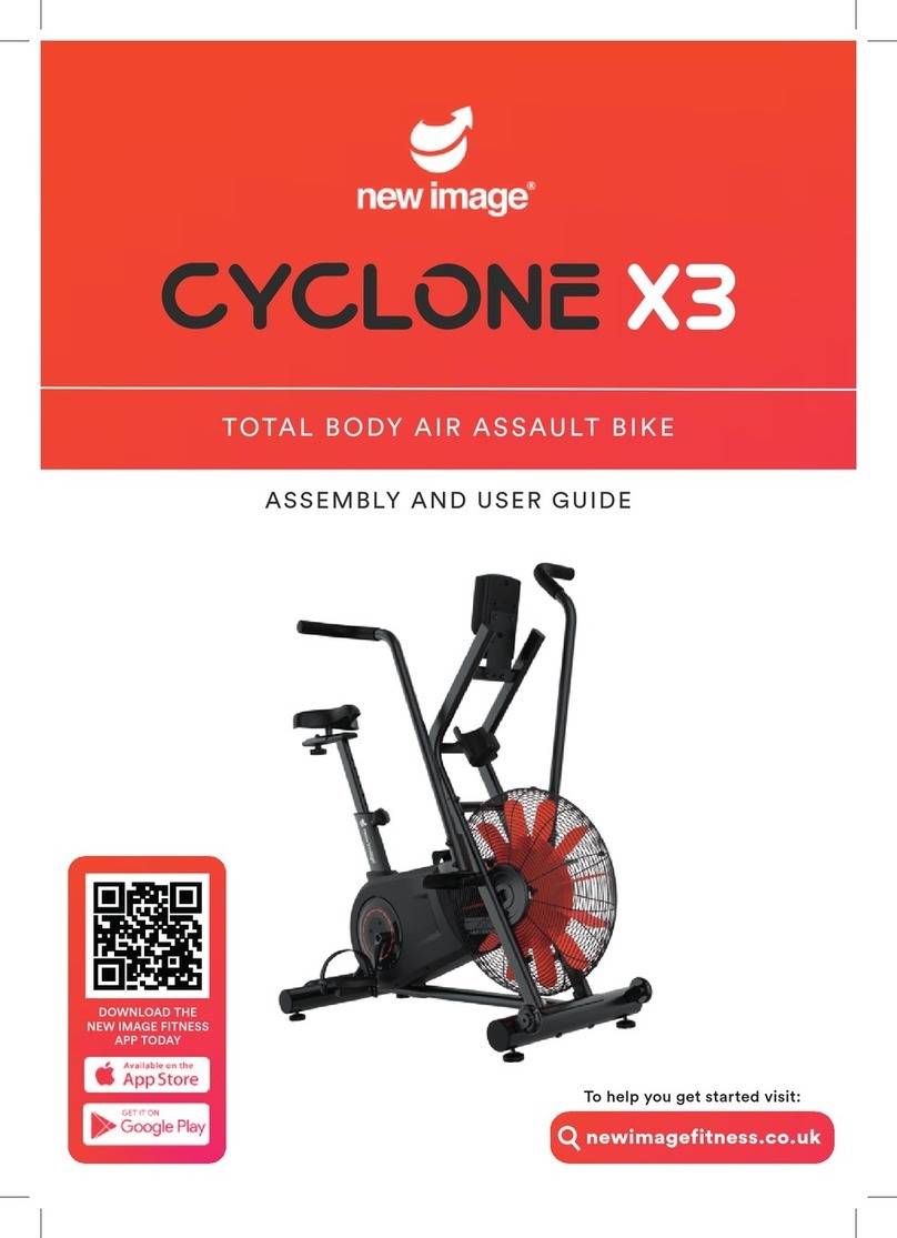
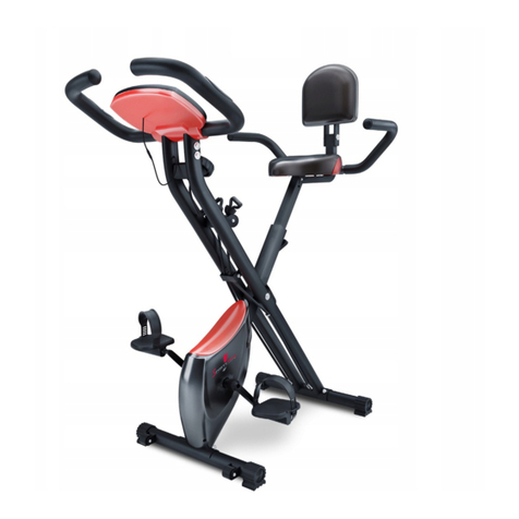
New Image SlimCycle User manual

ASSEMBLY AND USER GUIDE
The t wo-in-one e xe rci se bike that
combines c ard io with str ength t raining.
To help you get started visit:
newimagetness.co.uk
DOWNLOAD THE
NEW IMAGE FITNESS
APP TODAY

WARNINGS
BEFORE starting any tness or strength program, consult with your
physician or health ocial. This will ensure that you engage in the
proper strength or tness program for your age and physical condi-
tion.
Before using the Slim Cycle™ answer these questions:
• Have you been sick recently?
• Have you had prolonged dizziness recently?
• Have you been out of breath for no reason recently?
• Have you have had chest pain recently?
• Do you currently have any injuries preventing you from exercise?
• Are you pregnant?
• Do you have any conditions or reasons you shouldn't exercise?
• Are you over 35 years old and physically inactive?
• Have you been told by a doctor that you shouldn't exercise?
• IF YOU ANSWER "YES" TO ANY OF THE ABOVE QUESTIONS, YOU
SHOULD SEEK FURTHER ADVICE FROM YOUR DOCTOR PRIOR TO
USING THE SLIM CYCLE™.
• ALWAYS read the user's manual fully and follow all instructions,
this ensures your safety.
• ALWAYS use the Slim Cycle™ on solid, level ground and in a well lit
and ventilated area. Check that the seat and handlebars are
securely fastened before use.
• NEVER allow children to play on or around the bike. Injury could
result from a child's curiosity about the moving parts of the
stationary bike.
• ALWAYS set the bike up properly for your specic body type. The
Slim Cycle™ oers up/down and forward/backward adjustments
that are clearly marked to ensure a quick and easy customization
for each workout.
• ALWAYS check the stationary bike before use.
2

WARNINGS
• NEVER use the stationary bike if it is not properly/completely
assembled or is damaged in any way.
• NEVER use Slim Cycle™ when sick or fatigued.
• NEVER exceed the weight limit for this bike. The weight limit for
this bike is 300 pounds. Do not use the Slim Cycle™ if your body
weight is in excess of 300 pounds.
• ALWAYS wear proper attire and footwear that fully covers your feet.
Long hair should be tied back or tucked away. Ensure that any
shoelaces are tucked into your shoes.
• ALWAYS warm up/stretch before starting to exercise.
• ALWAYS be cautious when getting on and o the Slim Cycle™
• ALWAYS wait until the pedals have come to a complete stop before
taking your feet o of the pedals or dismounting. Do not stand or
climb on the handlebars.
• ALWAYS keep hands away from moving parts and ensure that
hands are never placed where there is no rubber handlebar grip.
• NEVER overexert yourself or work to exhaustion. If you feel faint,
dizzy, short of breath, or if you have chest or other pains, STOP
IMMEDIATELY! Consult your physician before using the Slim Cycle™
again.
• ALWAYS ensure that you have a water bottle lled with at least 12
oz. of water and a towel close by to absorb sweat from your body
and the handlebars.
• NEVER use the Slim Cycle™ in a standing position at high revolu-
tions per minute (RPM).
• ALWAYS keep your pelvis positioned over the center line of the Slim
Cycle™ stationary bike.
• NEVER adjust the resistance of the ywheel and the resistance of
the Slim Cycle™ Handlebar System while standing.
• NEVER use accessory attachments that have not been recommend-
ed by the manufacturer – using these attachments may cause
injury or damage to the bike and will aect the warranty of the
bike.
3

WARNINGS
• Please ensure that the Slim Cycle™ is wiped down after each use to
keep it sanitary.
• If any problems arise aecting the performance of the Slim Cycle™,
please contact the manufacturer immediately. Always ensure that
parts which undergo wear are checked regularly.
• THIS SAFETY INFORMATION AND USER'S MANUAL DOES NOT
REPLACE THE NEED TO BE ALERT AND TO USE COMMON SENSE
WHEN USING THE STATIONARY BIKE!
Do not mix old and new batteries.
Do not mix alkaline, standard (carbon-zinc), or rechargeable (Ni-Cd, Ni-MH,
etc) batteries.
Please note that changes or modications not expressly approved by the
party responsible for compliance could void the user's authority to operate
the equipment.
NOTE: This equipment has been tested and found to comply with the limits
for a Class B digital device, pursuant to Part 15 of the FCC Rules. These
limits are designed to provide reasonable protection against harmful
interference in a residential installation. This equipment generates, uses
and can radiate radio frequency energy and, if not installed and used in
accordance with the instructions, may cause harmful interference to radio
communications. However, there is no guarantee that interference will not
occur in a particular installation. If this equipment does cause harmful
interference to radio or television reception, which can be determined by
turning the equipment o and on, the user is encouraged to try to correct
the interference by one or more of the following measures:
• Reorient or relocate the receiving antenna.
• Increase the separation between the equipment and receiver.
• Connect the equipment into an outlet on a circuit dierent from that to
which the receiver is connected.
• Consult the dealer or an experienced radio/TV technician for help ed by
the manufacturer – using these attachments may cause injury or
damage to the bike and will aect the warranty of the bike.
4

INTRODUCTION
SLIM CYCLE ™
Congratulations on purchasing the Slim Cycle™, one of the highest
performance stationary bikes on the tness market. The Slim Cycle™
will oer you an excellent whole body workout through the inclu-
sion of upper-body movements on the bike. Accelerating, pushing
up from the saddle, and recovering are all natural and dynamic total
body movements for outdoor cyclists. Climbing steep hills and
sprinting involves signicant engagement through the core and
upper-body to control the lower-body. The Slim Cycle™ uses a
unique and revolutionary handlebar system to mimic and access this
level of realistic intensity. Welcome to the Slim Cycle™ revolution!
BEFORE YOU START
Prior to leaving the factory, your Slim Cycle™ was inspected and
thoroughly tested for proper operation. In order to minimize
damage through shipping, the bike was examined and carefully
packaged.
Your Slim Cycle TM stationary bike will arrive in 1 carton. When
receiving the package check for any damage. Discuss and point
out any damage to the delivery person and have them record any
damage on the delivery paperwork. Contact Customer Service to
report any damage (see details on the back of this manual). If you
follow the detailed instructions, then the Slim Cycle™ will be
unpacked and assembled with ease.
5

1. Main frame
2. Seat post
3. Rear foot
4. Front foot with rollers
5. Backrest support
6. Seat handles
7. Handlebars
8. Seat
9. Backrest
10. Control panel
11. Adjustment knob for
backrest
PARTS LIST
Also includes 2 AA batteries (not shown)
6
1.
2.3.
5.
6.
7.
8. 9.
10.
11. 12. 13.
15. 16.
14.
4.
12. Washers and screws
· 2 washers for seat handles
· 2 screws for seat handles
· 4 screws for backrest (Other
screws, washers, and nuts come
installed in parts. See ASSEMBLY
INSTRUCTIONS for details.)
13. Small hex key tool
14. Large hex key/screwdriver
tool
15. Wrench
16. Pedals
17. Pedal straps
6

ASSEMBLY INSTRUCTIONS
7
tallest
7
tallest
7
tallest
Loosen circular knob on
main frame and pull
outward to adjust recline
angle to 1 (tallest setting).
Take both nuts and
washers o of rear foot.
Place the nuts and washers
to the side for now.
Place the washer onto
screw.
Screw on the nut.
Install rear foot into rear
main frame leg. See
image to ensure rear foot
is installed on correct leg.
7

ASSEMBLY INSTRUCTIONS
Tighten nut onto screw
with included wrench.
Repeat on other side.
Take both nuts and
washers o of front foot
with rollers.
Place the nuts and washers
to the side for now.
Place the washer onto screw. Screw on the nut.
IInstall front foot onto
front main frame leg.
8
8
8
The rollers help to move the bike when it is tilted forward and
should not touch the oor when the bike is in a regular stand-
ing position. When properly installed, the rollers will face
outward from the front of the bike (see images). If the rollers
touch the oor, uninstall the foot, turn around, and reinstall.
8

ASSEMBLY INSTRUCTIONS
Tighten nut onto screw
with included wrench.
Repeat on other side.
Take nuts and washers o
of the seat cushion.
Place the nuts and washers
to the side for now.
Fit seat post onto seat
cushion screws.
Place the washers over the
screws from seat cushion.
Finger tighten each nut
onto the screws from seat
cushion. If dicult to
tighten, nut may be
upside-down.
9
9
9
9

ASSEMBLY INSTRUCTIONS
Tighten nut onto screw
with included wrench.
Repeat on other two nuts.
Loosen triangular knob
and remove from the
main frame.
Insert seat post into main
frame.
Secure knob back into
place at desired height.
10
10
10
Remove screw, nut, and
washer from the backrest
support.
Place the screw, nut, and
washer to the side for now.
10

ASSEMBLY INSTRUCTIONS
Align backrest support
with hole in the seat post.
Insert screw through hole
in backrest support.
Place washer onto the
screw.
Place nut on screw and
nger tighten. If dicult
to tighten, nut may be
upside-down.
Tighten the nut with the
included wrench.
Place washers onto screws
for the seat handles (see
parts diagram).
11
11
11
11

ASSEMBLY INSTRUCTIONS
Align the seat handles
with holes on the bottom
of the backrest support.
Place screws into holes
and nger tighten.
Tighten down screws with
included large hex
key/screwdriver tool.
Tighten down screws with
included large hex
key/screwdriver tool.
Align backrest against
backrest support. Insert
screws and nger tighten
(see parts diagram).
12
12
12
12

ASSEMBLY INSTRUCTIONS
Remove screws from
handle bar.
Place screws to the side
for now.
Feed handle bar posts into
the slots on the top of the
main frame.
Place screws into holes
and nger tighten.
Tighten down screws with
included small hex key tool.
Remove screws from the
back of the control panel.
13
13
13
13

ASSEMBLY INSTRUCTIONS
Starting with the largest
connector, feed each of the
three wires through the hole in
the center of handle bar bracket.
Place control panel onto
the handle bar bracket.
Insert screws and nger
tighten.
Connect each of the three wires
from bike to the control panel.
Either of the 2 small female
connectors can connect to either
of the 2 small male connectors.
Tighten screws with
included large hex
key/screwdriver tool.
14
14
14
14

Connect the right pedal to the right
crank arm. Both parts are marked R.
Hold the right pedal with one hand
and screw the pedal bolt onto the
crank arm with the other hand in a
standard clockwise motion. Finish
tightening with the included wrench.
Connect the left pedal to the left
crank arm. Both parts are marked L.
Hold the left pedal with one hand
and screw the pedal bolt onto the
crank arm with the other hand in a
non-standard counterclockwise
motion. Finish tightening with the
included wrench.
The strap marked R goes on the right
pedal. The strap marked L goes on the
left pedal. With the R or L marking facing
upward, attach the end of the strap with
3 holes to the inside of the pedal.
Attach the end of the strap with 4
holes to the outside of the pedal.
Adjust to your preference.
15
ASSEMBLY INSTRUCTIONS
READ THIS SECTION CAREFULLY
15
15
15
RIGHT bolt screws in CLOCKWISE
(standard direction)
R
LEFT bolt screws in COUNTERCLOCKWISE
(NON-standard direction)
L

16
CONTROL PANEL
BATTERY INSTALLATION
Requires 2 AA batteries (included).
Do not mix old and new batteries.
Do not mix alkaline, standard (carbon-zinc),
or rechargeable (NiCd, Ni-Mh, etc) batteries.
1. Open battery compart-
ment door on the back of
the Slim Cycle™ control
panel.
2. Note the diagram inside
the compartment that
shows the correct battery
installation polarity.
3. Install 2 AA batteries
(included) according to the
correct polarity.
4. Replace the battery
compartment door.
16
Slim
Cycle
16
Slim
Cycle

17
CONTROL PANEL
Display turns o after 4 minutes when not in use.
TIME, DIST, CAL, and PULSE: Default to previous setting until reset
([RESET]) or programmed with new setting ([SET]).
SCAN: Cycles through all functions below. Press [MODE] to make selection.
TIME: Press (RESET] to time workout or [SET] to program a countdown timer.
When countdown reaches 0, alarm will sound. Press any button to silence.
SPEED: Displays estimated MPH.
DIST: Press [RESET] to display distance in miles for current workout or [SET] to
program a countdown from distance goal. When countdown reaches 0, alarm will
sound. Press any button to silence.
CAL: Press [RESET] to display estimated calories expended or (SET] to program a
countdown from calorie goal. When countdown reaches O, alarm will sound. Press
any button to silence.
ODO: Displays total exercise miles of all workouts.
PULSE: Press [RESET] to display heart rate or [SET] to program a target heart rate.
User must hold the heart rate monitor grips on the handle bars for heart rate to
display. Whenever target heart rate is surpassed, alarm will sound. To silence,
remove hands from heart rate monitor grips or press (RESET].
[RESET] clears data from
selected mode.
• To reset all stored information
from previous workout, press
for 3 seconds.
• Does not clear total exercise
miles (ODO).
[MODE] selects mode.
• To reset all stored information
from previous workout, press
for 3 seconds.
• Does not clear total exercise
miles (ODO).
[SET] programs new setting for
selected mode.
• To increase setting more quick-
ly, press for 3 seconds. Release
and press again to program.
BUTTONS:
DISPLAY:
17
SCAN
TIME
SPEED
DIST
ODO
CAL
PULSE
RESET MODE SET

18
ADJUSTING RECLINE ANGLE
Level 1
18
18
Twist circular knob on main frame to the left to
loosen the bolt (do not fully remove). While stepping
on the rear foot, lift up on the bike while pulling the
knob to adjust angle.
Level 1 Level 2 Level 3

19
ADJUSTING SEAT HEIGHT
19
19
Level 1: Seat is lowered as far as the seat post will go.
Unscrew and remove triangular knob. Pull up on seat to
move levels. Screw knob back into place at desired level.

20
When desired length and resistance is reached, grab band on either
side of locking compartment and pull tight to lock band into place.
If band slips during workout, it may need to be pulled more tightly.
ADJUSTING PEDAL TENSION
Turn the tension control knob to adjust pedal tension from 1 to 8.
ADJUSTING RESISTANCE BANDS
SHORTEN BANDS
INCREASES RESISTANCE LENGTHEN BANDS
DECREASES RESISTANCE
Push the band up into the
band locking compartment.
Hold the band underneath the
handle and pull out. Only one
side adjusts, so if the band
cannot be pulled from one
side of the handle, pull from
the other side.
Push the band on one side of
handle down into the band
locking compartment. Only
one side adjusts, so if the band
cannot be pushed from one
side of the handle, push from
the other side. Pull the band
out of the other side of the
locking compartment.
Table of contents
Other New Image Fitness Equipment manuals

New Image
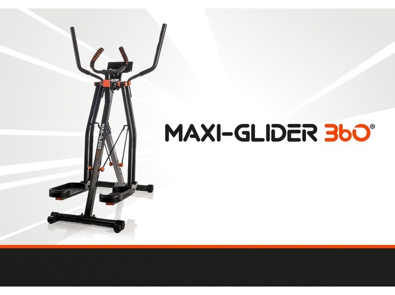
New Image Maxi-Glider 360 User manual
New Image
New Image FITT CUBE User manual

New Image
New Image FITT CUBE User manual
New Image
New Image Core Magic User manual
New Image
New Image FITT GYM User manual
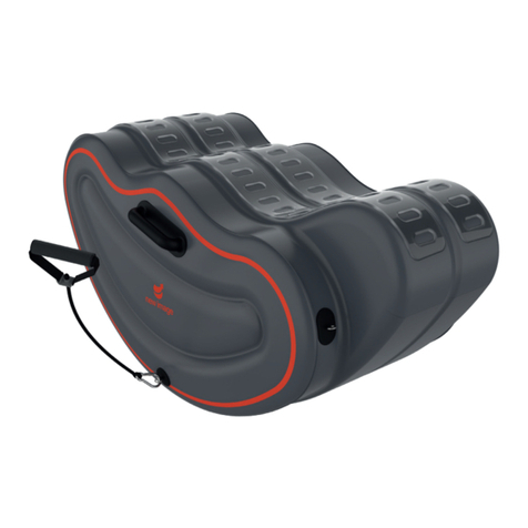
New Image
New Image FITT CURVE User manual
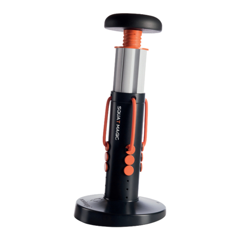
New Image
New Image Squat Magic User manual
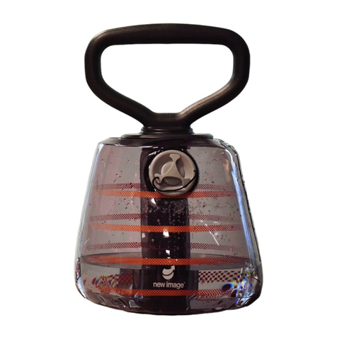
New Image
New Image FITT BELL User manual
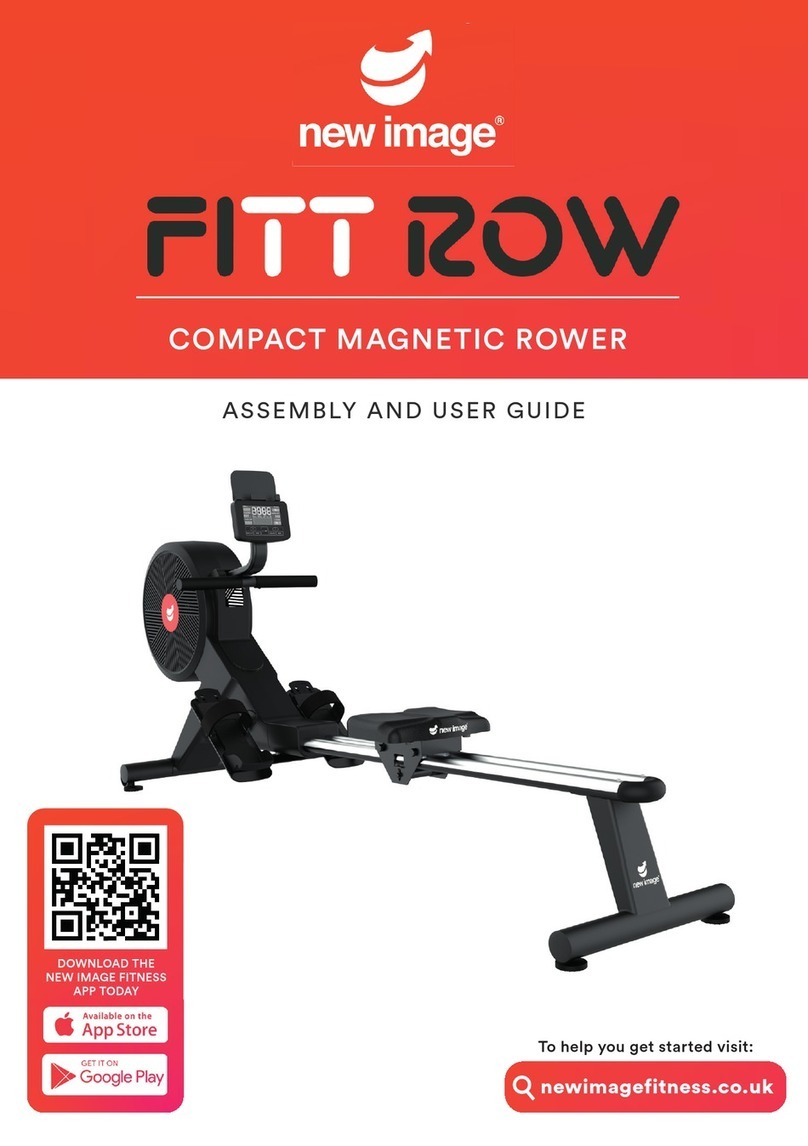
New Image
New Image FITT ROW User manual
New Image
New Image Maxi-Glider 360 User manual
