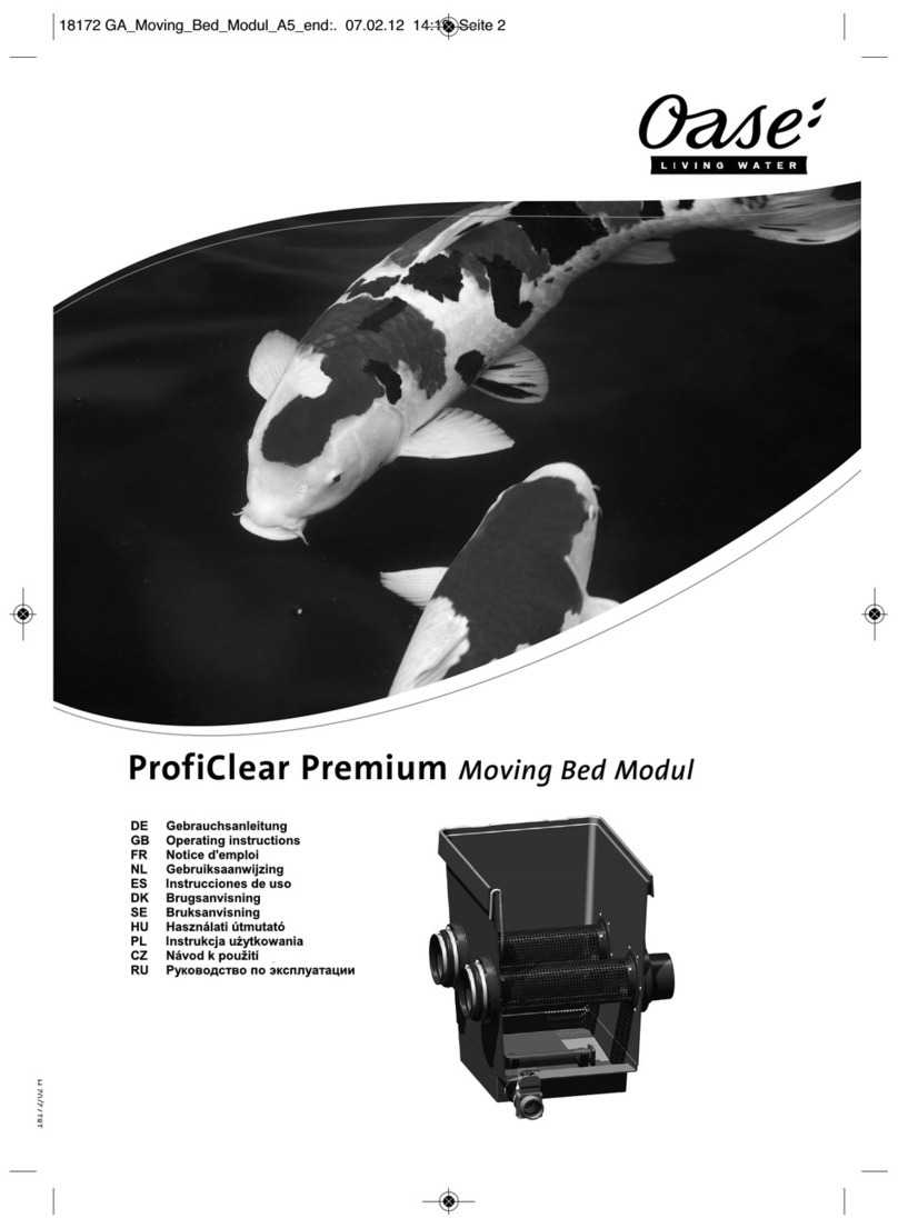
Oase ProfiClear Premium User manual

ProfiClear Premium Moving Bed Modul

2
-
-
A
ProfiClear0015
B
ProfiClea0006

3
-
-
C
ProfiClear0008Pr
D
ProfiClearr007

4
-
-
E
ProfiClear0009
F G
ProfiClear0038 ProfiClear0005

5
-
-
H
ProfiClear0039
I
ProfiClear0045

16
- DE -
11 Technische Daten
ProfiClear Premium Moving Bed Modul
Abmessungen L × B × H mm 830 × 665 × 815
ohne Wasser kg 45Gewicht
mit Wasser kg 270
gesamt m² 43Biologische Filteroberfläche
bei Füllung mit 50 l Hel-X-Bioelementen geschützt m² 35,5
Anzahl ST 2Einlauf
Anschluss mm
180
Anzahl ST 2Auslauf
Anschluss DN 150
Anzahl ST 1Schmutzauslauf
Anschluss DN 75
Minimum l/h 10000Umwälzleistung
Maximum l/h 25000

17
- GB -
Table of Contents
1 Information about these operating instructions ................................................................................ 18
2 Product Description.......................................................................................................................... 19
2.1 Delivery scope and unit configuration ...................................................................................... 19
2.2 Function description................................................................................................................. 20
2.3 Intended use ............................................................................................................................ 20
3 Safety information ............................................................................................................................ 21
4 Installation ........................................................................................................................................ 21
4.1 Preparing the unit connection .................................................................................................. 21
4.2 Connecting an external aerator pump...................................................................................... 22
5 Installation and connection............................................................................................................... 23
5.1 Installation planning ................................................................................................................. 23
5.2 Information regarding pipes ..................................................................................................... 23
5.3 Installing the filter module and connecting it to additional filter modules................................. 23
5.4 Pump fed system without ProfiClear Premium Individual Module: Fitting the discharge set... 24
5.5 Returning the water to the pond............................................................................................... 24
6 Commissioning/start-up ................................................................................................................... 25
7 Remedy of faults .............................................................................................................................. 25
8 Maintenance and cleaning ............................................................................................................... 26
8.1 Replace the aerator rod ........................................................................................................... 26
9 Storage/Over-wintering .................................................................................................................... 26
10 Disposal............................................................................................................................................ 26
11 Technical data.................................................................................................................................. 27
Spare parts ............................................................................................................................................. 127
- GB -

18
- GB -
Translation of the original Operating Instructions
1 Information about these operating instructions
Welcome to OASE Living Water. You made a good choice with the purchase of this product ProfiClear
Premium Moving Bed Modul.
Prior to commissioning the unit, please read the instructions of use carefully and fully familiarise yourself
with the unit. Ensure that all work on and with this unit is only carried out in accordance with these
instructions.
Adhere to the safety information for the correct and safe use of the unit.
Keep these instructions in a safe place! Please also hand over the instructions when passing the unit on
to a new owner.
The symbols used in this operating manual have the following meanings:
Risk of injury to persons due to dangerous electrical voltage
This symbol indicates an imminent danger, which can lead to death or severe injuries if the appropriate
measures are not taken.
Risk of personal injury caused by a general source of danger
This symbol indicates an imminent danger, which can lead to death or severe injuries if the appropriate
measures are not taken.
Important information for trouble-free operation.
A Reference to one or more figures. In this example: Reference to Fig. A.
oReference to another section.

19
- GB -
2 Product Description
The OASE filter system ProfiClear Premium includes the filter modules "Drum Filter Module", "Moving
Bed Module" and "Individual Module". The filter system can be operated as a pump fed or gravity fed
system. All filter modules are suitable for both system except for the Drum Filter Module.
2.1 Delivery scope and unit configuration
A ProfiClear Premium Moving Bed Module quantity
1 Container cover 1x
2 Container
provides a space for the Hel-X biomedia to move around in (3)
1x
3 25-l bag of Hel-X biomedia
Hel-X biomedia (only 5 shown in the diagram), once colonised by bacteria, act as filter
elements for biologically cleaning the water
2x
4180 mm inlet 2x
5 Diffusor 2x
6 Meshed tube with diffusor (5)
together with the active aerator rod (8), creates turbulence in the water flowing into the
container
blocks the outlet and inlet for the Hel-X biomedia
is fastened at both ends in four places with two snap-on rivets each (14)
2x
7 DN 150 outlet 2x
8 Aerator rod
enriches the water in the container with oxygen and keeps the Hel-X biomedia in constant
motion
1x
9 DN 75 dirt outlet with slide valve 1x
10 9 mm air hose with air connection (11)
for connecting an external aerator pump to the aerator rod (8)
1x
11 Air connection
for connecting a 9 mm air hose
1x
12 9 mm tee for dividing the air flow 1x
13 4/9 adapter
for connecting 4 mm air hoses to the air connection (11)
1x
Snap-on rivet
for fastening the meshed tubes
32x
14
Snap-on rivet
spare
2x
— 100 ml can of BioKick CWS 1x
— Accessory kit containing fastening material 1x
Not included in the delivery scope but available as accessories:
H ProfiClear Premium discharge set, pump fed, Order No.: 50949, contains:
2x DN 110 adapters
2 x DN 110 pipe bends
1x holding plate
1x

20
- GB -
2.2 Function description
The ProfiClear Premium Moving Bed Module is designed for biological filtering of pond water. Hel-X
biomedia are used as filter elements.
Hel-X biomedia ensure the effective break-down of nutrients and contaminants in the water. Over the
course of time, the surface of the biomedia is colonised by bacteria responsible for nitrification and
denitrification. They clean the water before it leaves the container. The fluidized bed process (action of
the water flow and oxygen supply) and the bypass technology ensure optimum motion of the Hel-X
biomedia even at high flowthrough rates, and removal of dead biomass.
50 l of Hel-X biomedia are able to break down the nutrients from approx. 300 g fish food per day,
given optimum conditions. If required, this can be increased to 75 l, i.e. 450 g/day.
The development of the biology in the filter takes several days. It can be accelerated by adding BioKick
CWS.
Biokick CWS contains millions of active micro-organisms. They start cleaning the water immediately
and act as starter bacteria. The biology in the filter is fully developed within only a few days.
Nitrification is the process by which ammonia/ammonium and nitrite are removed from the water by
special bacteria. These substances can build up in the water, for example as a result of fish food and
fish excrement. Ammonia is particularly toxic for fish.
Nitrification takes place in two steps. In the first step, the bacteria convert the ammonia/ammonium into
nitrite. In the second step, other bacteria convert this nitrite into nitrate, which although non-toxic,
promotes the growth of algae. Both steps use oxygen that is taken from the water.
Denitrification is the process by which nitrate is broken down to nitrite and then gaseous nitrogen. The
bacteria use the nitrate nitrogen as a source of oxygen and convert it into atmospheric nitrogen.
Atmospheric nitrogen cannot be used by algae and aquatic plants. Denitrification only takes place to a
very small extent in an environment with a high oxygen content.
OASE recommends: If you are giving your fish large amounts of food, ensure that there are sufficient
aquatic plants or change the water regularly.
2.3 Intended use
ProfiClear Premium Moving Bed Modul, in the following termed "unit", and all other parts from the
delivery scope may be used exclusively as follows:
ŹFor cleaning garden ponds.
ŹOperation under observance of the technical data.
The following restrictions apply to the unit:
ŹOnly operate with water at a water temperature of min. +4 °C to max. +35 °C.
ŹNever use the unit to convey fluids other than water.
ŹDo not use for commercial or industrial purposes.
ŹDo not use in conjunction with chemicals, foodstuff, easily flammable or explosive substances.

21
- GB -
3 Safety information
The company OASE has built this unit according to the state of the art and the valid safety regulations.
Despite the above, hazards for persons and assets can emanate from this unit if it is used in an
improper manner or not in accordance with its intended use, or if the safety instructions are ignored.
For safety reasons, children and young persons under 16 years of age as well as persons who
cannot recognise possible danger or who are not familiar with these operating instructions, are
not permitted to use the unit. Keep children under supervision to ensure that they do not play
with the unit.
4 Installation
ŹThe following tools are required:
10 mm ring spanner
7 mm socket spanner
PZ3 Phillips screwdriver
Cordless drill/screwdriver with PZ3 bit (do not set to "drill"!)
4.1 Preparing the unit connection
Before installing, connecting and starting up the unit, perform the following tasks:
1 Fit 1× DN 75 slide valve (A 9)
2 Fit 2× 180 mm inlets (A 4)
2 Fit 2× DN 150 outlets (A 7)
2 Fit 2× meshed tubes (A 6)
ŹRemove the container cover.
Fitting the DN 75 slide valve
5.
How to proceed:
B
1. Fit the slide valve into the connecting sleeve and secure with a hose clip.
2. Fit the connecting sleeve onto the connection.
3. Secure the holding plate of the slide valve to the outside of the container with cap nuts.
4. Secure the hose clip on the connection.
Fitting the
180 mm inlet
5.
How to proceed:
C
1. If not already done: Fit the sealing ring into the wall of the container from the outside.
Ensure that the raised marking is at the top and aligned in relation to the hole pattern.
2. Fit the inlet to the sealing ring.
Ensure that the raised marking is at the top and aligned in relation to the hole pattern.
3. Fasten the sealing ring and inlet from the inside with oval head screws.
Tighten all screws diagonally using the cordless screwdriver to ensure that the sealing ring is
uniformly applied. Further tighten the screws using a Phillips screwdriver.
4. Fit the rubber sleeve over the inlet and fasten with a hose clip.
Turn the hose clip so that the screw is accessible from the side. This facilitates later installation
work.

22
- GB -
Fitting the DN 150 outlet
5.
How to proceed:
D
1. If not already done: Fit the sealing ring into the wall of the container from the outside.
Ensure that the raised marking is at the top and aligned in relation to the hole pattern.
2. Fit the outlet to the sealing ring.
Ensure that the raised marking is at the top and aligned in relation to the hole pattern.
3. Fasten the sealing ring and outlet from the inside with oval head screws.
Tighten all screws diagonally using the cordless screwdriver to ensure that the sealing ring is
uniformly applied. Further tighten the screws using a Phillips screwdriver.
Fitting the meshed tube
4.
How to proceed:
E
1. Clamp the meshed tube between the two sealing rings. As far as the direction is concerned:
Ensure that the end of the meshed tube containing the diffusor is located on the inlet side (side
with aerator connection).
Ensure that the white cable binder fastening the diffusor in the meshed tube is turned to the
position of the outside top fastening hole for the snap-on rivet so that the diffusor is pointing in the
direction of the aerator rod.
Ensure that the meshed tube completely encloses the sealing ring and can be turned easily.
2. Use four snap-on rivets at each end to secure the meshed tube from slipping: Two at the top and
two at the bottom.
Securing with snap-on rivets from the top:
Reach into the sealing ring from the outside of the container and press the first snap-on rivet from
the inside upwards and outwards through the fastening hole in the sealing ring and the meshed
tube.
Fix this snap-on rivet from above (inside of the container) with a second snap-on rivet.
Repeat the process with the other snap-on rivets.
Securing with snap-on rivets from underneath:
From the inside of the container press the first snap-on rivet from underneath upwards and
inwards through the meshed tube and the fastening hole in the sealing ring.
Reach into the sealing ring from outside the container and fix this snap-on rivet from above with a
second snap-on rivet.
4.2 Connecting an external aerator pump
ŹConnect the aerator rod in the container to an external aerator pump.
OASE recommends: OASE AquaOxy 2000 pond aerator or more powerful.
ŹSeveral aerator pumps may be required depending on the number of filter modules to be provided
with air.
ŹFrom AquaOxy 4800 at least two filter modules can be aerated with one aerator pump. Use the tee
included in the delivery scope for dividing the air flow. Ensure that the connection hoses (air supply
hoses) are the same length for all filter modules.
3.
How to proceed:
F
1. Connect the hose from the external aerator pump to the air connection and fit the air connection
onto the container.
For thinner 4 mm air hoses, use the 4/9 mm adapter and secure the connection with a cable
binder if necessary.

23
- GB -
5 Installation and connection
5.1 Installation planning
Note:
Use suitable transport and lifting aids to transport and install the unit.
The unit weighs more than 25 kg (oTechnical Data).
Plan the installation of the filter system. With careful planning, taking the ambient conditions into
account, you will obtain optimum operating results.
The following conditions must be met:
ŹAs the filter modules are very heavy when filled, they must be placed on a suitable base (at least on
slabs, but preferably on a poured concrete base) to prevent them from subsiding.
ŹPlan sufficient space for carrying out cleaning and maintenance work.
ŹDrain the dirty water into the drain or far enough away from the pond so that it cannot flow back into
the pond.
If the coarse soiling and dirty water both run into the same pipe, it is important to use at least DN
110 pipes.
ŹUse a suitable system for removing coarse soiling, e.g. ProfiClear Premium Drum Filter Module.
5.2 Information regarding pipes
ŹUse suitable pipes.
ŹDo not use any right-angled bends. Bends with a maximum angle of 45° are very efficient.
ŹGlue plastic pipes to ensure a permanent and reliable joint or use socket joints with clips to stop
them from coming apart.
ŹStanding water in pipes can freeze when there is a hard frost and cause pipes to burst. For this
reason, lay the pipes and hoses with a gradient (50 mm/m) to ensure that they can run empty.
ŹFor gravity fed systems, it must be possible to shut off the supply from the pond and the return to the
pond for maintenance and repair work. For this reason, install suitable slide valves.
5.3 Installing the filter module and connecting it to additional filter modules
A maximum of three Moving Bed Modules can be installed one after the other.
2.
How to proceed:
G
1. Push the Moving Bed Module container towards the preceding module (Drum Filter Module or other
Moving Bed Module) until the outlet socket of the preceding module slides inside the rubber socket
of the Moving Bed Module up to the stop.
The slide valves of the soiled water drains are all located on the same side.
2. Secure the connection with a hose clip.
3. First position the hose clip screw at the top, then tighten. This facilitates later installation steps.
Information about the pump fed system!
If no ProfiClear Premium Individual Module is connected to the last Moving Bed Module, OASE
recommends the following: To ensure an optimum water level in the container fit the ProfiClear Premium
discharge set (Order No.: 50949).

24
- GB -
5.4 Pump fed system without ProfiClear Premium Individual Module: Fitting the discharge set
Fit an outlet adapter with DN 110 pipe bend to each DN 150 outlet to ensure a suitable level of water in
the filter container. The height of the pipe bend outlet determines how high the water can rise in the filter
containers. Based on the physical principle of communicating pipes, the water balances out to the same
level in all containers. Ensure that the centre of the pipe bend outlet is 169 mm below the top edge of
the container. It is not necessary to fit pipe bends if the last filter module is a ProfiClear Premium
Individual Module.
OASE provides a suitable discharge set (Order No. 50949). It consists of two pipe bends/DN 110
adapters with holding plate.
4.
How to proceed:
H
1. If not already done: Fit the sealing ring into the wall of the container from the outside.
Ensure that the raised marking is at the top and aligned in relation to the hole pattern.
2. Fit the outlet adapter to the sealing ring.
Ensure that the raised marking is at the top and aligned in relation to the hole pattern.
3. Fasten the sealing ring and outlet adapter from the inside with oval head screws.
Tighten all screws diagonally using the cordless screwdriver to ensure that the sealing ring is
uniformly applied. Further tighten the screws using a Phillips screwdriver.
4. Fit the pipe bend set together in the specified order and fasten to the outlet adapter.
5. Guide the holding plate over the pipe bend and align the pipe elements if necessary.
6. Insert the screws with expansion seals through the holes from the inside. Screw the holding plate
from the outside to the container wall with cap nuts.
5.5 Returning the water to the pond
Once it has passed through all the cleaning stages, the clean water has to be returned to the pond.
There are various possibilities for this depending on the system used (please refer to the operating
manual for the Individual Module).

25
- GB -
6 Commissioning/start-up
Two 25 l bags of Hel-X biomedia (50 l) are required for operating a Moving Bed Module. Optionally, 75 l
can be used (supplementary kit Order No.: 51060).
7.
How to proceed:
1. Close the slide valve for the DN 75 dirt outlet at the bottom of the container.
2. Check that the entire filter system (pipes and hoses) is complete.
3. Fill the container with water:
Pump fed system: Switch on the filter pump.
Gravity fed system: Open the slide valves (supply and return) of the ProfiClear Premium filter
series to allow the water to flow.
4. Check all pipes, hoses and their connections for leaks.
Expansion seals may leak initially until they have fully expanded on contact with water.
5. Fill the container with Hel-X biomedia.
Ensure that the Hel-X biomedia can move around freely in the container.
It can take several weeks for the Hel-X biomedia to become completely colonised. Uncolonised
Hex-X biomedia tend to float more.
6. Add filter starter BioKick CWS.
7. Fit the container cover.
8. When all filter containers are filled with water, switch on the other electrical units (e.g. filter pumps).
If using filter starters (e.g. OASE BioKick CWS), do not operate any UVC clarifying units for at least
24 hours so as not to disturb the colonisation of the filter media by micro-organisms.
7 Remedy of faults
Malfunction Possible cause Remedy
Filter pump not switched on Switch on the filter pump, connect the power plugNo flow of water
Supply to filter system or return to pond
blocked
Clean the supply and/or return
Bottom drain, pipe or hose blocked Clean, replace if necessary
Hose kinked Check hose, and replace if necessary
Water flow insufficient
Excessive loss in lines Reduce line length to necessary minimum
Insufficient Hel-X biomedia used Use more Hel-X biomedia if necessaryWater contains too much
ammonium/nitrite Unit has only been in operation for a short
time
The full biological cleaning effect is only achieved
after several weeks
The meshed tube has slipped Correct the position of the meshed tubeHel-X biomedia are being
flushed out Defective meshed tube Replace the meshed tube
Aerator rod is blocked Replace the aerator rodLess movement of the Hel-
X biomedia
Aerator pump malfunction Check the aerator pump
Less movement of the new
Hel-X biomedia
Hel-X biomedia are not yet fully colonised It takes several weeks for the biomedia to become
colonised by bacteria. Wait for the natural process
to take place.

26
- GB -
8 Maintenance and cleaning
The filter system is self-cleaning. Dead biomass drops to the bottom and has to be removed. To do this,
open the DN 75 dirt outlet for approx. 10 seconds.
ŹThe entire filter system only needs to be taken out of operation for cleaning and maintenance if it is
extremely soiled.
ŹDo not use any chemical cleaning agents as they would kill the filter bacteria.
9.
How to proceed:
1. Switch off all filter pumps.
2. Switch off all other electrical units of the filter system (e.g. UVC clarifying unit).
3. Only applies to gravity fed systems: Close the slide valves (supply and return) of the filters
connected in series to prevent further water flow.
4. Open the slide valve for the DN 75 dirt outlet at the bottom of the container and dispose of the soiled
water in a permissible way.
5. Carry out cleaning measures.
Rinse the Hel-X biomedia in the container with running water.
6. Close the slide valve (dirt outlet).
7. Start up the filter system again (oStart-up).
8.1 Replace the aerator rod
8.
How to proceed:
I
1. Remove approx. 2/3 of the Hel-X biomedia and keep moist. After completing the maintenance
measures, return the Hel-X biomedia to the container.
2. Pull the aerator rod out of the clamping holder at the bottom of the container.
3. Disconnect the hose from the aerator rod and fit it onto the new aerator rod.
4. Press the new aerator rod into the clamping holder.
9 Storage/Over-wintering
The unit is protected from frost:
The unit can be operated as long as the water temperature does not go below +4 °C.
The unit is not protected from frost:
Take the unit out of operation at water temperatures below +8° C or, at the latest, when freezing
temperatures are to be expected.
ŹDrain the unit as far as possible, clean thoroughly and check for damage.
ŹEmpty all hoses, pipes and connections as far as possible.
ŹLeave the slide valves open.
ŹCover the filter container to prevent the penetration of rain water.
ŹProtect pipes and slide valves that are in contact with water from frost.
10 Disposal
Support us in our endeavour to keep our environment intact, and adhere to the following disposal
information!
Dispose of the unit in accordance with the national legal regulations.

27
- GB -
11 Technical data
ProfiClear Premium Moving Bed Module
Dimensions L × W × H mm 830 × 665 × 815
without water kg 45Weight
with water kg 270
total m² 43Biological filter surface
when filled with 50 l Hel-X biomedia protected m² 35,5
quantity pce. 2Inlet
connection mm
180
quantity pce. 2outlet
connection DN 150
quantity pce. 1Dirt outlet
connection DN 75
minimum l/h 10000Circulating capacity
maximum l/h 25000

127
ProfiClear 0054

128
ProfiClear0055

129
ProfiClear0056
Other manuals for ProfiClear Premium
5
Table of contents
Other Oase Control Unit manuals
Popular Control Unit manuals by other brands

AERMEC
AERMEC MCR user manual

Red Valve
Red Valve Tideflex 35 Series Installation, operation and maintenance manual

BST
BST ekr 500 operating manual

Quantifi Photonics
Quantifi Photonics PASSIVE Series user manual

SMART Embedded Computing
SMART Embedded Computing PrAMC-7311 Installation and use

ATEN
ATEN CN8000 user manual

Lowenstein Medical
Lowenstein Medical prismaCONNECT Instructions for use

Inovance
Inovance GL20-0800END user guide

Accutrol
Accutrol AVC5000 Installation & operation manual

Dungs
Dungs SAV 100065 MD instruction manual

Hypex Electronics
Hypex Electronics UcD Supply HG Mono user manual

Asco
Asco 317 Series Installation and maintenance instructions