Newall dp1200 User manual

User Manual
DP1200 Digital Readout


2
Specification Page 3
Electrical Page 3
Physical Page 3
Environment Page 3
Accreditation Page 3
Disposal Page 3
Input and Resolution Page 3
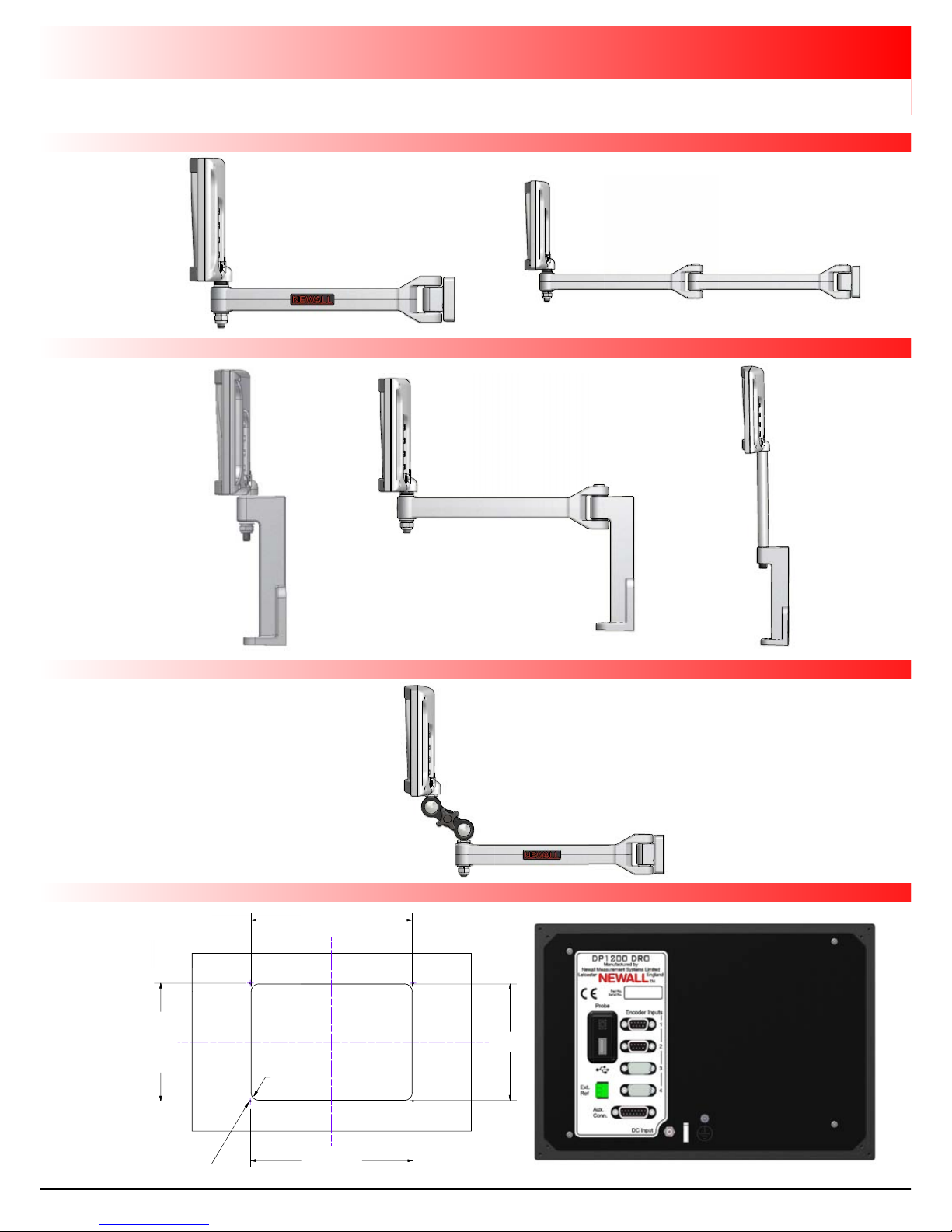
ounting Options Page 4
Mill Mount Page 4
Lathe Mount Page 4
Adjustable Mount Page 4
Panel Mount Page 4
Connection Details Page 5
Important Information Page 5
Connections Page 5
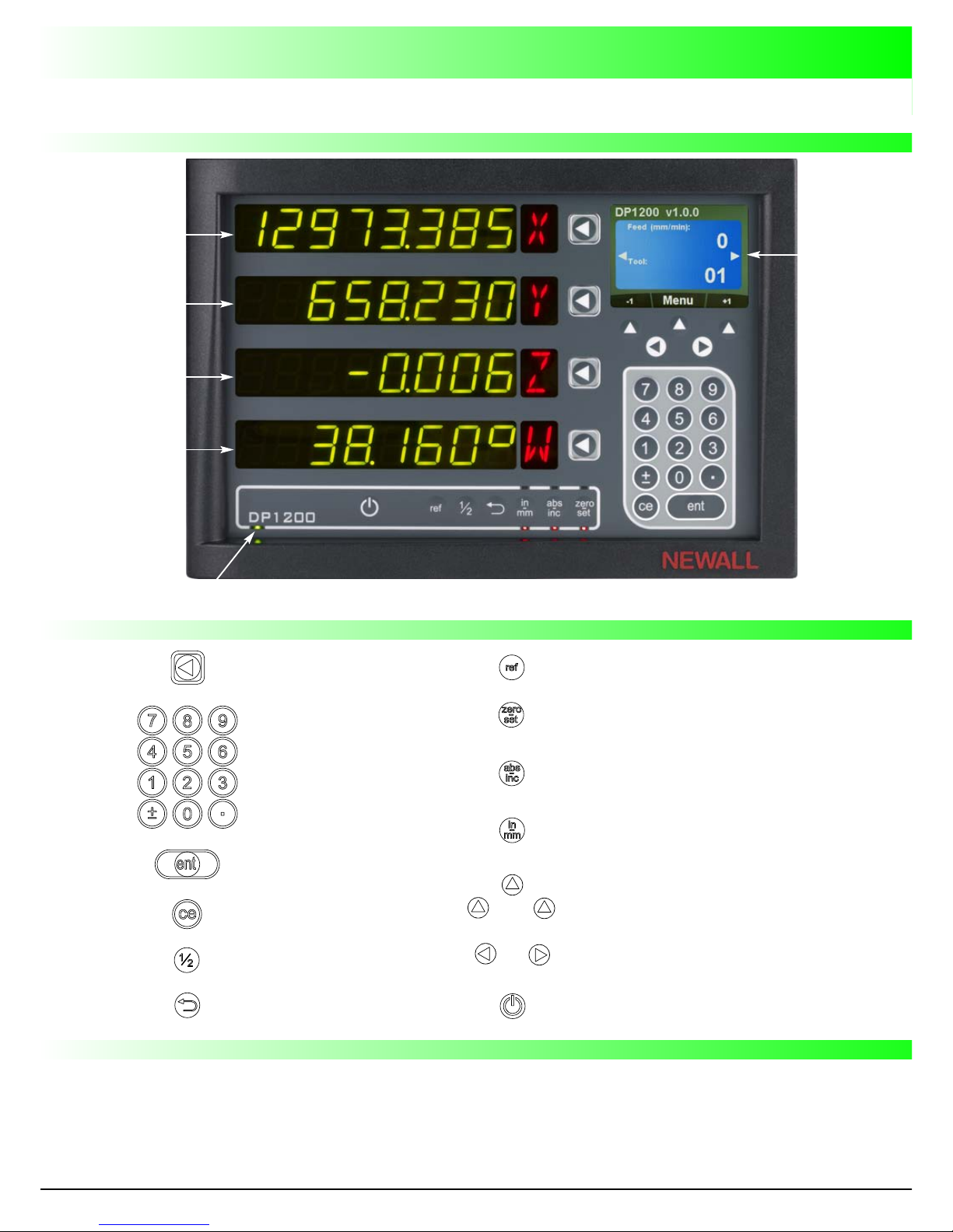
Display and Keypad Page 6
Understanding the Display Page 6
Understanding the Keypad Page 6
Invalid Key Warning Page 6
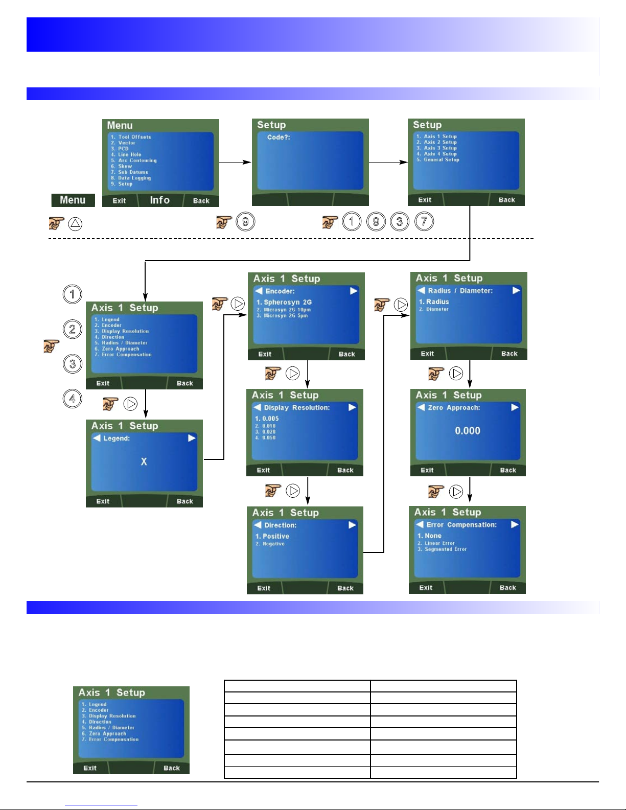
Setting up the Unit Page 7
Setup Menu Navigation Page 7
Navigating Axes 1, 2, 3, 4 (Analogue) Setup Page 7
Quick Navigation Axes 1, 2, 3, 4 (Analogue) Setup Page 7
Navigating Axis 4 Setup (Digital Linear) Page 8
Quick Navigation of Axis 4 Setup (Digital Linear) Page 8
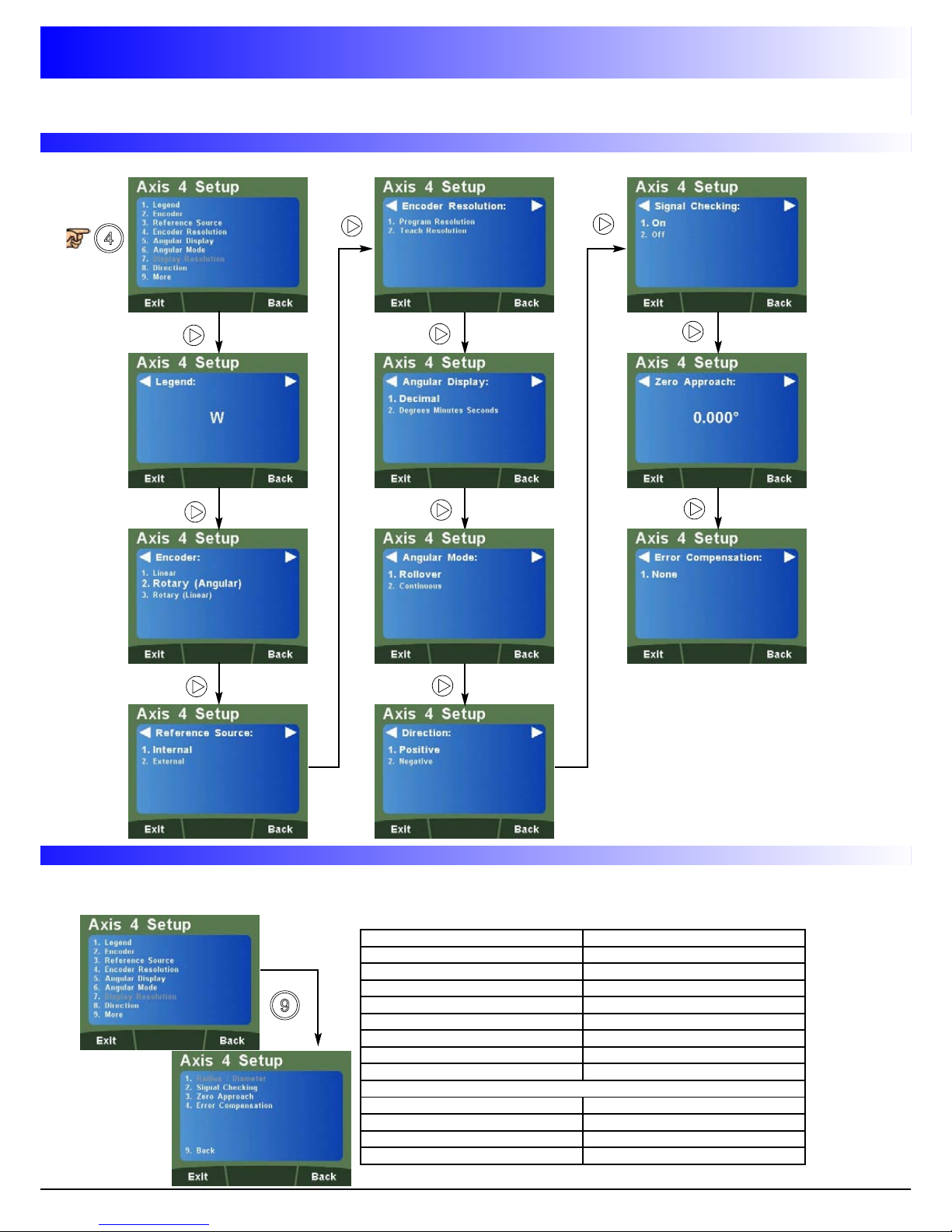
Navigating Axis 4 Setup (Digital Rotary Angular) Page 9
Quick Navigation of Axis 4 Setup (Digital Rot Ang) Page 9
Navigating Axis 4 Setup (Digital Rotary Linear) Page 10
Quick Navigation of Axis 4 Setup (Digital Rot Lin) Page 10
Navigating General Setup Page 11
Quick Navigation of General Setup Page 11
Setup Axis 1, 2, 3 & 4 (Analogue) Page 12
Legend Setup Page 12
Encoder Setup Page 12
Display Resolution Setup Page 12
Direction Setup Page 12
Radius / Diameter (Measure Setup) Page 12
Zero Approach Setup Page 13
Error Compensation Page 13
Types of Machine Error Page 14
Linear Error Compensation Page 14
Error Compensation Setup Page 15
Linear Error Compensation Setup Page 15
Segmented Error Compensation Page 16
Segmented Error Compensation Setup Page 16/17
Setup Axis 4 (Digital Linear) Page 18
Legend Setup Page 18
Encoder Setup Page 18
Reference Source Setup Page 18
Encoder Resolution Setup Page 18
Display Resolution Setup Page 18
Direction Setup Page 19
Radius / Diameter (Measure Setup) Page 19
Signal Checking Setup Page 19
Zero Approach Setup Page 19
Error Compensation Setup Page 19
Setup Axis 4 (Digital Rotary Angular) Page 20
Legend Setup Page 20
Encoder Setup Page 20
Reference Source Setup Page 20
Encoder Resolution Setup Page 20
Setup Axis 4 (Digital Rotary Angular) continued
Angular Display Setup Page 21
Angle Mode Setup Page 21
Direction Setup Page 21
Signal Checking Setup Page 21
Zero Approach Setup Page 21
Setup Axis 4 (Digital Rotary Linear) Page 22
Legend Setup Page 22
Encoder Setup Page 22
Reference Source Setup Page 22
Encoder Resolution Setup Page 22
Display Resolution Setup Page 23
Direction Setup Page 23
Radius / Diameter (Measure Setup) Page 23
Signal Checking Setup Page 23
Zero Approach Setup Page 23
Error Compensation Setup Page 23
General Setup Page 24
Language Setup Page 24
Application Setup Page 24
Plane Setup Page 24
Axis Coupling Setup Page 24
unctions Setup Page 25
Probe Diameter Setup Page 25
Beep Setup Page 25
LCD Brightness Setup Page 25
Sleep Setup Page 26
Unlock Axis Page 26
Reset Setup Page 26
Standard Functions Page 27
Absolute / Incremental Page 27
Inch / mm Page 27
Zero and Preset an Axis Page 28
Undo unction Page 28
Half unction / Centre ind Page 29
Digifind / Reference Page 29
Sub Datums / Memory (SDM) Page 30/31
Sleep Mode Page 31
RS232 (Data Logging) / Data Acquisition Page 32
RS232 Connections Page 32
RS232 Setup Page 32/33
RS232 Output Data ormat Page 34
ill Functions Page 35
PCD / Bolt Hole Circle Page 35/36
Line Hole Page 37/38
Arc Contouring Page 39/40
Polar Coordinates Page 41
Skew Page 42/43
Lathe Functions Page 44
Tool Offsets Page 44/45
Vector Page 46
Taper Angle Page 47
Axis Summing Page 48
Troubleshooting Guide Page 49
Contents

EU Directive 73/23/EEC (Low Voltage Directive)
BS EN 55022:1998 Class B
BS EN 55024:1998
Input to Power Supply Unit (Supplied)
100-240V (47-63Hz)
External switch-mode - Output voltage 15VDC
Input Voltage to DP1200 15-24VDC ±10%
Conforms to Low Voltage Directive
Height 215mm (8 ½") Depth 68mm (2 ¾")
Width 310mm (12 ¼") Weight 3.5kg (7 ¾lb)
Climatic Range Storage Temperature -20°C (-4° ) to 70°C (158° )
Working Temperature -10°C (14° ) to 50°C (122° )
Working Humidity 95% R.H. at 31°C (87.8° )
IP-Ingress Protection IP54 Panel Mount
IP40 Stand Alone
At the end of its life, you should dispose of the DP1200 system in a safe manner applicable to
electrical goods
Do not burn
The casework is suitable for recycling. Please consult local regulations on disposal of electrical
equipment
Encoder inputs 1, 2 & 3 can be used with Spherosyn 2G and Microsyn 2G analogue encoders.
Encoder input 4 can be used with Spherosyn 2G / Microsyn 2G or 5v TTL Quadrature, depending on
the model ordered.
Note: It is possible to upgrade the DP1200 from a 2 or 3 Axis up to 4 Axes, See Page 26 - Unlock Axis.
Display Resolution Options
Spherosyn 2G or icrosyn 2G 10µm
5µm (0.0002")
10µm (0.0005")
20µm (0.001")
50µm (0.002")
Newall Measurement Systems Limited reserves the right to make changes to this specification without notice
Electrical
Physical
Environment
Accreditation
Disposal
Input & Resolutions
icrosyn 2G 5µm
1µm (0.00005")
2µm (0.0001")
5µm (0.0002")
10µm (0.0005")
3
Specification

Lathe ount (Non Adjustable)
Adjustable ount Options
Panel ount Option
This section details the various mounting options for the DP1200, both the standard version and
the panel mount version.
ill ount (Non Adjustable)
4
297.0
202.0
Cutout
Corners R5 Min./R15 Max.
300.00 Fixing Ctrs.
205.00FixingCtrs.
P4.50 0 4off
S
Panel cut out
Mounting Options

This chapter details the cable connections for the DP1200.
Important Information
Connections
Encoder inputs 1, 2 & 3 can be used with Spherosyn 2G and Microsyn 2G analogue encoders.
Encoder input 4 can be used with Spherosyn 2G / Microsyn 2G or 5v TTL Quadrature, depending on
the model ordered.
Please ensure that:
All cables are secured to prevent the connectors from dropping into hazardous positions
(for example the floor or coolant tray) when unplugged.
All cables are routed to prevent them from being caught on moving parts.
Before the machine power is turned on, the DP1200 is grounded to the machine, using the
braided grounding lead provided.
The power has been disconnected, before you connect the encoder(s).
DO NOT CONNECT THIS UNIT DIRECTLY TO THE AINS SUPPLY.
If the Newall encoder has a round 7 pin connector, an adaptor cable (part no. 307-80980) is required.
Contact your local Newall supplier for details.
Encoder input connection
1, 2, 3 or 4 according to model
Auxiliary / RS232 output
Cabinet equipotential terminal
for grounding to machine
External PSU input
Cable clamp
5
Probe connection
External reference
connection
Connection Details

This section explains how to interpret the display and use the keypad.
Understanding The Display
Understanding The Keypad
Axis Selection Key
Numeric Keys
Enter Key
Clear Numeric Entry
Centre ind
Undo Key
Digifind / Reference
Switches between Zero and
Axis Preset modes
Switches between Absolute
and Incremental modes
Soft Keys (left, middle & right)
Navigation Keys
Switches between
Inch and mm display
Sleep Key
Axis 1
Axis 2
Axis 3
Axis 4
Power LED
Message
Display
LCD
Invalid Key Warning
The DP1200 is equipped with a visual and audible indication to warn the user when an invalid key has
been pressed.
If an invalid key has been pressed, all the displays will flash on and off twice along with a
double beep tone. No operation will change until a correct key for that operation has been pressed.
6
Display and Keypad

Numeric Key Setup Function
1 Legend Setup
2 Encoder Setup
3 Display Resolution Setup
4 Direction Setup
5 Radius / Diameter Setup
6 Zero Approach Setup
7 Error Compensation Setup
Setup enu Navigation
How to enter setup
7
Navigating Axes 1, 2, 3 & 4 (Analogue) Setup
The DP1200 supports a quick navigation feature using the LCD screen and numeric keys, enabling the
user to navigate to specific areas without scrolling through each and every menu. This is particularly
useful when navigating to one specific item.
Below are the quick navigation keys for the setup of Axes 1, 2, 3 or 4 dependant on model (where
navigation to the main axis setup menu is completed).
Quick Navigation of Axes 1, 2, 3 & 4 (Analogue) Setup
or
or
or
Setting Up The Unit

Setting Up The Unit
Setup enu Navigation (continued)
8
Navigating Axis 4 Setup (Digital Linear)
Quick Navigation of Axis 4 Setup (Digital Linear)
Numeric Key Setup Function
1 Legend Setup
2 Encoder Setup
3 Reference Source Setup
4 Resolution Setup
7 Display Resolution Setup
8 Direction Setup
9 More Options
Press Key 9 for the options below
1 Radius / Diameter Setup
2 Signal Checking Setup
3 Zero Approach Setup
4 Error Compensation Setup
9 Back to Previous Options
The quick navigation feature for the setup of axis 4 digital linear is detailed below (where navigation
to the main axis setup menu is completed).

9
Setting Up The Unit
Setup enu Navigation (continued)
Navigating Axis 4 Setup (Digital Rotary Angular)
Quick Navigation of Axis 4 Setup (Digital Rotary Angular)
Numeric Key Setup Function
1 Legend Setup
2 Encoder Setup
3 Reference Source Setup
4 Resolution Setup
5 Angular Display Setup
6 Angular Mode Setup
8 Direction Setup
9 More Options
Press Key 9 for the options below
2 Signal Checking Setup
3 Zero Approach Setup
4 Error Compensation Setup
9 Back to Previous Options
The quick navigation feature for the setup of axis 4 digital rotary angular is detailed below (where
navigation to the main axis setup menu is completed).

10
Setting Up The Unit
Setup enu Navigation (continued)
Navigating Axis 4 Setup (Digital Rotary Linear)
Quick Navigation of Axis 4 Setup (Digital Rotary Linear)
Numeric Key Setup Function
1 Legend Setup
2 Encoder Setup
3 Reference Source Setup
4 Resolution Setup
7 Display Resolution Setup
8 Direction Setup
9 More Options
Press Key 9 for the options below
1 Radius / Diameter Setup
2 Signal Checking Setup
3 Zero Approach Setup
4 Error Compensation Setup
9 Back to Previous Options
The quick navigation feature for the setup of axis 4 digital rotary linear is detailed below (where navi-
gation to the main axis setup menu is completed).

Setting Up The Unit
11
Setup enu Navigation (continued)
Navigating General Setup
Quick Navigation of General Setup
Numeric Key Setup Function
1 Language Setup
2 Application Setup
3 Plane Setup
4 Mill Summing Setup
5 unctions Setup
6 Probe Diameter Setup
7 Beep Setup
8 LCD Brightness Setup
9 More Options
Press Key 9 for the options below
1 Sleep Setup
2 Unlock Axis
3 Reset Setup
9 Back to Previous Options
The quick navigation feature for general setup is detailed below (where navigation to the main axis
setup menu is completed).

Navigate to
Setting Up The Unit
Encoder Setup
Display Resolution Setup
Direction Setup
12
Legend Setup
Setup Axis 1, 2, 3 & 4 (Analogue)
The legend of the axis can be set to any of the options in the table below.
Navigate to
Use the key list to select
the desired character
Key 1stPress 2ndPress 3rdPress 4thPress 5thPress
0 0 N/A N/A N/A N/A
1 X1Y1Z11 N/A
2 A B C 2 N/A
3 D E 3 N/A
4 G H I 4 N/A
5 J K L 5 N/A
6 M N O 6 N/A
7 P Q R S 7
8 T U V 8 N/A
9 W X Y Z 9
Navigate to To select Spherosyn 2G as the encoder type
To select icrosyn 2G 10µm as the encoder type
To select icrosyn 2G 5µm as the encoder type
Note: The encoder type must match the actual encoder in use,
or the DP1200 will not display correctly
Navigate to Spherosyn 2G & icrosyn 2G 10µm
To select 5µm (0.0002”)
To select 10µm (0.0005”)
To select 20µm (0.001”)
To select 50µm (0.002”)
icrosyn 2G 5µm
To select 1µm (0.00005”)
To select 2µm (0.0001”)
To select 5µm (0.0002”)
To select 10µm (0.0005”)
To select Positive
To select Negative
Example:
If the current setting is Positive and the measurement increases
from right to left, changing the setting to Negative will cause the
measurement to decrease.
Radius / Diameter ( easure Setup)
Navigate to To select Radius
To select Diameter
The radius/diameter function allows the operator to display actual
(radius) or twice-actual (diameter) measurements for each axis.
This function is generally used in turning applications, such as the
cross travel on a lathe displaying the diameter reading rather than the
radius, is the desired result.

Default is 0.000
Setting Up The Unit
Zero Approach Setup
13
Navigate to
This setting provides a visual indication that one or more axes are approaching zero. This is done by
using the far left LED segment on each axis, as the axis approaches zero, each segment of the '0'
lights up in quick succession. Once zero has been reached, the '0' to the far left will be constantly on.
Enter any value using the numeric keys to provide zero approach
limits. This can be entered in inches or millimeters by toggling the
tkey.
Note: To disable the zero approach function, enter a value of 0.000.
Error Compensation
A digital readout (DRO) system helps to improve productivity. It decreases the number of scrapped
parts, as the operator no longer has to be concerned about making mistakes related to counting the
revolutions on the dials. The DRO system also helps to eliminate some errors related to ballscrew
backlash.
The DRO system will operate to its published accuracy, provided all components are in working order
and properly installed. ield calibration is not necessary.
Accuracy problems with machined parts may be caused by machine error, DRO system error, or a
combination of both. The first step in determining the source of error is to check the DRO system. This
is completed by comparing the movement of the Newall reader head to the position reading shown on
the display. A high accuracy standard, such as a laser interferometer is required. A dial indicator can
be used to check short distances, but a laser provides the best results. if a dial indicator must be used,
be sure it is the highest available accuracy.
Instructions
Check the accuracy of the DRO system
1. Place the target of the laser or the needle of the dial indicator directly on the Newall reader head. It
is absolutely critical to take the readings directly from the Newall reader head. If a dial indicator
tmust be used, be sure that the needle of the indicator is perpendicular to the reader head and not
tangled. If readings are taken anywhere else on the machine, machine errors may distort the results.
2. When the reader head moves, the movement registers on the laser / indicator and the DRO display.
3. Set the laser / dial indicator and DRO position displays to 0.
4. Make a series of movements and compare the position readings between the laser / dial indicator
t and the DRO display. If the readings match within the accuracy specified, then the DRO system is
toperating properly. If this is the case, proceed to the next step, “Evaluate machine errors”. If the
treadings do not match, contact your local Newall Service Representative before proceeding with
terror compensation.
Evaluate machine errors
1. Put the laser target / dial indicator on the part of the machine where the machining is performed.
2. Make a series of movements and compare the position readings between the laser / dial indicator t
tand the DRO display. The difference between the laser / dial indicator reading and the reading on
tthe DRO display is the machine error.
3. Plot the machine error along the entire axis of travel to determine the nature of the error. If it is a
linear error, you can use linear error compensation. If the error is not linear, you should use
segmented error compensation.

Setting Up The Unit
Types of achine Error
There are many types of machine error, including pitch, roll, yaw, flatness, straightness, and Abbé error.
The diagrams below demonstrate these errors.
Way errors
Pitch
Axis
Yaw
Axis
Typical Yaw
Deviation Straightness
Roll Axis
Travel
Flatness
Typical Pitch
Deviation
14
Linear Error Compensation
In this mode, a single constant correction factor is applied for each axis to all displayed measure-
ments. The correction factor is calculated, and specified in parts per million (ppm).
In this mode a single constant correction factor for each axis is applied to all displayed measurements.
As you follow the procedure ensure that you approach each edge from opposite directions, then
subtract the width of the tool from the value displayed on the DP1200. The DP1200 Automatically takes
into account the probe diameter as per setting (Linear Only).
(Fig 1)
Abbé error
A
B
C2
C2
B2
A2
B1
C1
B1
A1
C1
A1
Shown with encoder on concave side
of bearing path
Shown with encoder on convex side of
bearing path
greater than
End Effector Linear
encoder
Encoder
End Effector Linear
encoder
Encoderless than
encoder
Error
Travel
Tool or
Probe
standard distance
measured distance

15
Setting Up The Unit
Error Compensation Setup
Navigate to
To select no Compensation (None)
To select Linear Error Compensation
To select Segmented Error Compensation
Linear Error Compensation Setup
To select Teach mode
To select Program mode
Teach ode
0.000 499.875
500.000
Program ode
irst determine the correction factor required. To do this, use the following equation.
(In the example the standard distance is 500.000mm and the measured distance is 500.200mm)
Correction factor = error / actual x 1,000,000
Correction factor = (500 - 500.200) / 500.000 x 1,000,000
Correction factor = -400
Teach mode is an easier way of calculating linear errors using the DP1200 to automatically calculate
the error, by comparing the actual measurement and the physical movement.
ollow the steps below;
Move tool / probe to start position (See ig 1) Move tool / probe to end position (See ig 1)
Enter the actual measurement using the numerical keypad Check / Accept correction factor

Setting Up The Unit
16
Segmented Error Compensation
The scale travel is broken down into as many as 200 user-defined segments, each with their own
correction factor, measured against a high-accuracy standard. The following parameters need to be
identified;
Each Correction Point is measured with respect to the Starting Point - zero - which is usually set
close to one end of the scale. The Reference Point can be set anywhere along the scale, and does
not need to coincide with either the absolute datum or any of the correction points. However, it may
be convenient to make the absolute datum and the reference point the same.
Always approach the Starting Point, Correction Points and Reference Point from the same direction.
If not, the size of the tool or probe will render the measurement inaccurate.
Starting point - zero
Reference point Correction points
Error
Travel
0
1
2
3
4
5
6
Segmented Error Compensation Setup
To select Teach mode
To select Program mode
Teach ode
Enter movement
using the numeric
keypad
Select “Yes” to move on to
point 2 (maximum 200 points).
Select “No” to accept the
segmented compensation.

Setting Up The Unit
17
Program ode
Position 1: Enter a value using the numeric key-
pad for the 1st correction point (I.E 5.000)
Correction 1: Enter a value using the numeric
keypad for the correction value (I.E -0.010)
Note: The correction value is limited to a
minimum of 0.005mm (0.0002”)
to navigate between points. A maximum of 200 points are available.
to accept the compensation at the point reached.
The program mode enables the user to define the correction points manually and then enter them into
the DP1200. The position is where the correction point occurs, and the correction point is the value to
be corrected at that point.

Setting Up The Unit
18
Legend Setup
Please refer to Page 10, Legend Setup
Setup Axis 4 (Digital Linear)
For models with 5v TTL quadrature 4th axis
Encoder Setup
To select Linear as the encoder type
Display Resolution
Enter the resolution that is required to be displayed using the numerical keys.
The displayed resolution can only be the same or higher than the encoder resolution.
Example:
Linear Encoder has a resolution of 1µm (0.001) and is to be displayed at 5µm (0.005).
Navigate to
Note: Inch / mm function must be set to reflect entered resolution
Encoder Resolution
Enter the resolution of the encoder for the 4th digital axis using the numerical keys.
It is important the resolution of the encoder is entered exactly or inaccurate measurements will occur.
Example:
Linear encoder has a resolution of 0.001mm.
Navigate to
Note: Inch / mm function must be set to reflect entered resolution
Reference Source Setup
To select Internal referencing
To select External referencing
The DP1200 is capable of using an internal reference or an external reference source for the digital 4th
axis. An internal reference is the reference mark provided by the encoder.

Setting Up The Unit
Error Compensation Setup
19
Signal Checking Setup
The DP1200 has the facility to detect if the encoder attached to the 4th digital axis has become
disconnected, sustained severe cable damage, or with some encoders, experienced electronic failure.
To enable Signal Checking
To disable Signal Checking
Zero Approach Setup
Please refer to Page 11, Zero Approach Setup
Please refer to Page 11, Error Compensation Explanation
Page 12, Type of achine Error
Page 12, Linear Error Compensation Explanation
Page 13, Linear Compensation Setup
Direction Setup
Please refer to Page 10, Direction Setup
Radius / Diameter ( easure Setup)
Please refer to Page 10, Radius / Diameter ( easure Setup)
ode of Operation
The detection mechanism monitors the incoming signals from the encoder to look for an illegal
combination of input levels.
If the encoder becomes disconnected, then the illegal
input combination is generated internally within the
DP1200. The display will then show ‘SIG AIL’. If it is
possible to correct the fault, press the axis zero key to
reset that display. If the ‘SIG AIL’ message continues
to be displayed then the fault has not been corrected.
A B R Status
L L H SIG AIL
L H X OK
H L X OK
X X L OK
X = any state i.e can be either high (H) or low (L).
Note: Please check the encoder specification for information on the synchronisation of the index
marker pulse. If the encoder is capable of generating the illegal condition (A low, B low and RM high),
then signal checking function should be TURNED OFF.
Table of contents
Other Newall Other manuals
Popular Other manuals by other brands

AEMC
AEMC Simple Logger II L104 user manual

Panasonic
Panasonic TK-AB50 operating instructions

BENDIX
BENDIX ROTO CHAMBERS manual

Pittsburgh Automotive
Pittsburgh Automotive 64982 Owner's manual & safety instructions

Johnson Outdoors
Johnson Outdoors MINN KOTA Talon quick start guide

Nidec-Shimpo
Nidec-Shimpo RK-5T manual

AquaCare
AquaCare TKF Series instruction manual

Cateye
Cateye GAME BIKE CONTROL Operation manual

Curt Manufacturing
Curt Manufacturing 13269 installation instructions

ViaAqua
ViaAqua MULTI-SKIMMER manual

Delta Electronics
Delta Electronics EXIO14RAE user guide

Texas Instruments
Texas Instruments CC2541 quick start guide