NewLine Anita 2 Sided User manual
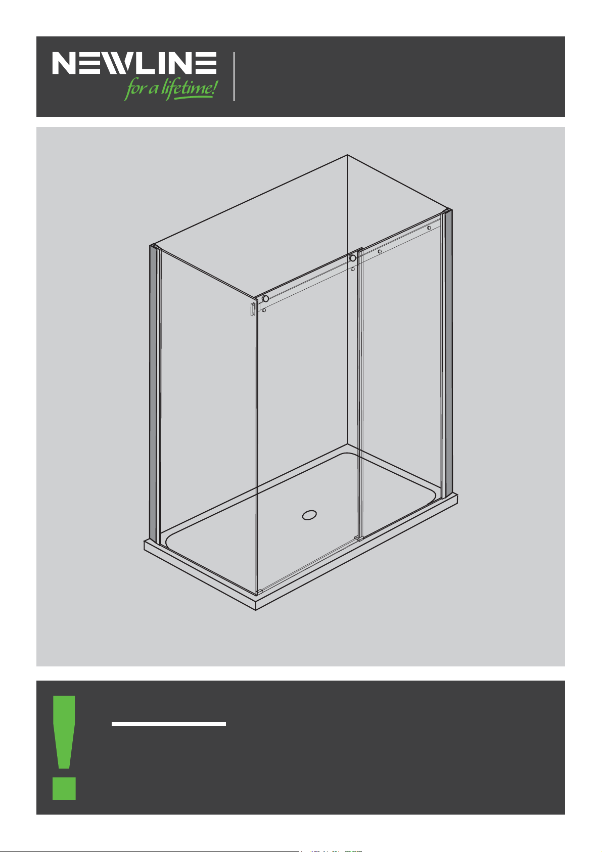
Anita 2 Sided and 3 Sided Alcove
1. When you receive your Anita shower check contents for any freight damage or defects.
2. $GYLVH1HZOLQHRQLIDQ\GDPDJHKDVRFFXUUHGRUGHIHFWLGHQWLзHGZLWKLQ
KRXUVRIUHFHLYLQJWKHJRRGVVRWKLVFDQEHUHFWLзHG
3. Do not proceed with installation until resolved as there cannot be a valid claim later.
Important!
INSTRUCTION MANUAL
JULY 2020
2 SIDED & 3 SIDED ALCOVE

1
WARRANTY
• Faulty goods are covered under warranty. Visit www.newline.nz for warranty information.
• Breakages incurred during installation are not covered under warranty.
• Installations must conform to the instructions to be covered by the warranty.
HEALTH AND SAFETY
Toughened Glass:
• Do not rework pre-cut glass panels. Cutting or altering a glass panel will cause it to explode without warning.
• <UWHJRHSSNSHZZHZZLTISPLZ:[HUKNSHZZVUZVM[WHJRHNPUN^OLUP[PZVU[OLÅVVYHUKHNHPUZ[H^HSS*HYLT\Z[
be taken not to strike any edge or corner against a hard surface as this will chip and destroy the glass panel.
Installation:
• Glass panels and assemblies are heavy. Two man lifting is recommended for handling and installation.
• Determine positioning of wiring and piping within wall cavities before shower installation. Mark their positions to
ensure electrical and piping areas are avoided.
• Wear appropriate protective clothing and eye protection during installation.
TOOLS REQUIRED
NEWLINE RECOMMENDS A SKILLED TRADESMAN ACQUAINTED WITH
SHOWER INSTALLATIONS TO ENSURE THE VERY BEST OUTCOME.
IMPORTANT INFORMATION
AFTERCARE
• ;OLZOV^LYT\Z[ILZX\LLNLLKKV^UHM[LYLHJOZOV^LY;OVYV\NOS`JSLHU^LLRS`^P[OHTPJYVÄILYJSV[O
mild detergent and water. Rinse with clean water and squeegee and wiped dry.

2
ENSURE YOU TICK THE SPECIFIC BOXES THAT APPLY AS YOU PROGRESS
Floor & Walls:-SVVYT\Z[SL]LS^P[OUVKLÅLJ[PVUHUK^HSSZWS\TIHUKÅH[;OPZPZVMHSSPTWVY[HUJLMVYH
successful installation.
Tray and Liner:0UZ[HSSH[PVUMVY[PSL[YH`ZVYHJY`SPJ[YH`ZSPULYHYLZ\WWSPLK^P[O[OLZWLJPÄJ[YH`VYKLYLK
Frame:
1. :DOO3URзOH2SWLRQV
Acrylic Tray: Centred 20mm off outside of tray edge
Hob Tile Tray:*LU[YLKTTVMMÄUPZOLK[PSLLKNL[OPZ^PSSHSSV^TTVMM[YH`ILMVYL[PSPUN
Level Entry:*LU[YLKH[[OL[YHUZP[PVUSPUL^OLYLZSVWLILNPUZ
2. 6ROLGз[LQJIRU:DOO5DLO%UDFNHW
(ZPKLKVUS`VU[OLKVVYZPKLHKQHJLU[^HSS
([[HJOHTT]LY[PJHSSLUN[OVMMYHTPUNVU[OLPUZPKLVM[OL^HSSWYVÄSLZ[\KZ[HY[PUNH[[OLSV^LZ[
WVPU[VMTTVMM[OLÅVVY[VTTH[[OL[VW
3. 6ROLGз[LQJVIRUZDOOPRXQWHGSOXPELQJзWWLQJV
Consult with the plumber.
Wet Grade lining: Aqualine Gib. or equivalent “must be used behind all shower installations for compliance”
Plumbing: Use a registered plumber for installation all supply and waste items prior to tray and wall linings.
:DWHUSURRзQJϋ3UR)LQLVK7LOH7UD\Vό This must comply with AS/NZS 4858:2004 and be undertaken by
JLY[PÄLKHWWSPJH[VYHUKH7YVK\JLY:[H[LTLU[WYV]PKLK;OLYLPZHSPZ[VMWYV]LUZ`Z[LTZVUV\Y^LIZP[L
www.newline.co.nz
Tiling:
1. 5L^SPULYLX\PYLZ[OL\ZLVMJVTWSL[LZ`Z[LTZI`SPJLUJLK[YHPULKHWWSPJH[VYZ>H[LYWYVVÄUN;PSL
(KOLZP]L.YV\[PUNHUK:PSPJVULKL[HPSPUNMVYM\SSHJJV\U[HIPSP[`HUKWLYMVYTHUJLYLX\PYLTLU[Z
2. ;OL[PSLZT\Z[JVUMVYT[VNYHKPLU[ZWYV]PKLK^P[O[OL¸7YV-PUPZO;PSL;YH`¹[VJVTWS`[V5A)\PSKPUN
Code.
4VPZ[\YLYL[HPUTLU[VM[OLZOV^LYLUJSVZ\YLT\Z[ILKL[HPSLK^P[OH¸>H[LY:[VW¹[VTLL[[OL(:
requirements.
4. The line where shower screen sits must be level for an acceptable installation.
PREPARATION CHECKLIST
ANITA SHOWER - INDEX
;OLYLHYL[OYLLSH`V\[WHNLZWYV]PKLK7SLHZLLUZ\YL`V\ZLSLJ[[OLJVYYLJ[SH`V\[WHNLHUKJVTIPUL
this with the installation details.
2 Exploded View Assembly Diagram Page 3
:PKLK(JY`SPJ3H`V\[7SHU( Page 4
:PKLK;PSL^P[O7YV-PUPZO;PSL;YH`3H`V\[7SHU) Page 5
(SJV]L+VVY6US`3H`V\[7SHU* Page 6
Installation Steps Page 7
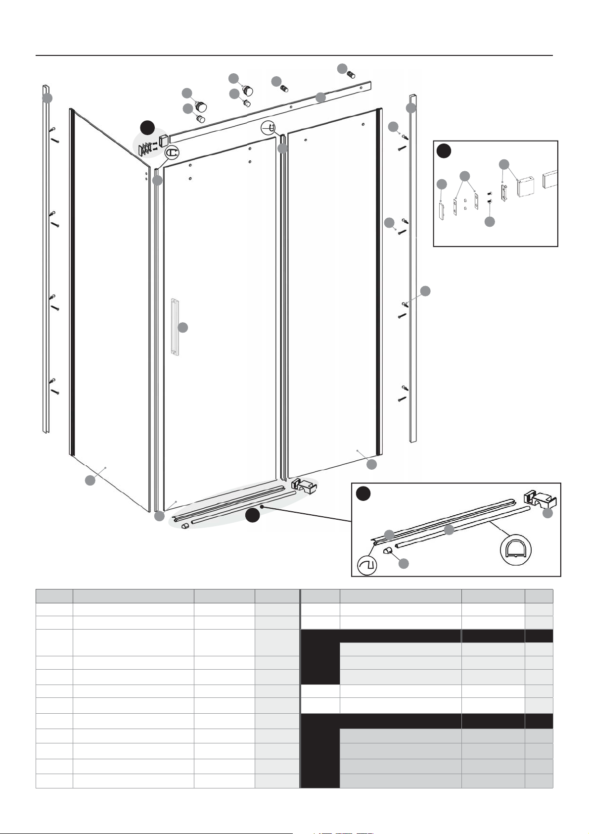
ANITA SHOWER - ASSEMBLY DIAGRAM
REF. DESCRIPTION PART NO. QTY REF. DESCRIPTION PART NO. QTY
1>HSS7YVÄSL K8618 2 Rail H8601 1
29L[\YU7HULS 1 14 Rail Joiner Assembly K0970 1
+VVY7HULS 1Gasket + Wall Cap Set 2 1
15 Wall Gaskets 2
4 Buffer Strip I6105 116 Wall Cap 1
5 Buffer/Seal Strip I8526 117 Threaded Screws M5 x 10 2
6 Handle Set / 118-YVU[-P_LK7HULS 2
73VJR0U2UVI:L[Z+VVY K1519 219>H[LY+LÅLJ[VY I8595 1
8 Front Glass To Rail Fixing K1526 2Screw Pack K0895 1
9 End Block H8540 220 :JYL^Z4_ 8
10 :SPKPUN)SVJRZ39 LH: H8557
RH: H8564 221 Screws M4 x 8 8
11 Water Bar H8571 124 Screw Cover Caps 8
12 9VSSLY:L[Z+VVY K8588 225 *::JYL^Z4_ 2
112
8
8
5
4
1
3
12
13
24
20
18
19
9
11
10
7
7
21
2
6
16
15
14
17
A
A
B
B
Screw Pack
4
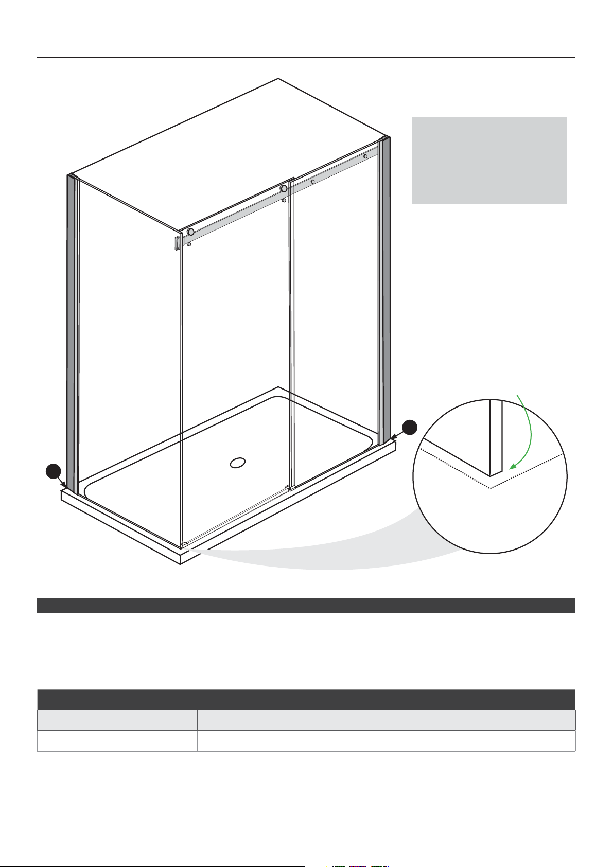
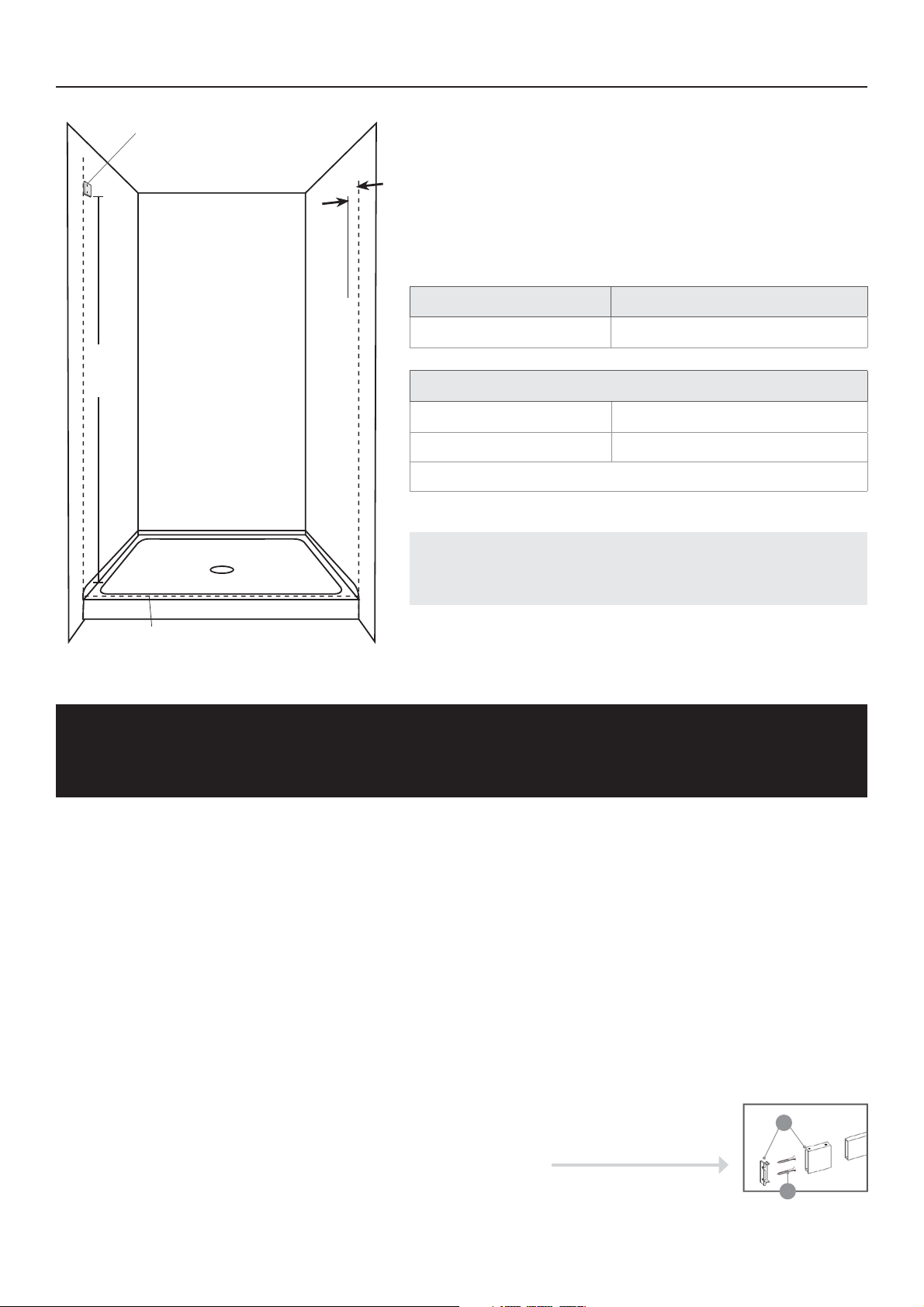
ANITA SHOWER: ACRYLIC 2 SIDED - LAYOUT PLAN A
DOTTED LINE:
6<;,9*/(55,3)6<5+(9@305,
RETURN GLASS EDGE:
44)(*2-964+6;;,+305,
IMPORTANT DETAIL
A
A
MINIMUM / MAXIMUM TABLE
SHOWER TYPE FRONT DOOR PANEL (A) MIN/MAX RETURN PANEL (B) MIN/MAX
1200 x 915 TT TT
OPTION A: ANITA ACRYLIC SHOWER (APPLIES TO 1200 X 915)
Anita Acrylic Shower with Newline Acrylic Tray and ABS/Acrylic Liner:
:L[V\[[OL(UP[H:OV^LYI`THYRPUNV\[[OLV\[ZPKLSPULVM[OL^HSSJOHUULSZ(20mm in from the outside edge
of the tray. This will allow for walls leaning or bowed inwards by 4mm. Greater variances will need to be calculated
using the MIn/Max table below.
NOTE: All measurements
HZZ\TL[OLÅVVYPZSL]LS
the walls are plumb and all
Z\YMHJLZHYLÅH[(U`]HYPH[PVU
T\Z[ILHKQ\Z[LKMVYPU[OL
measurements provided.
5
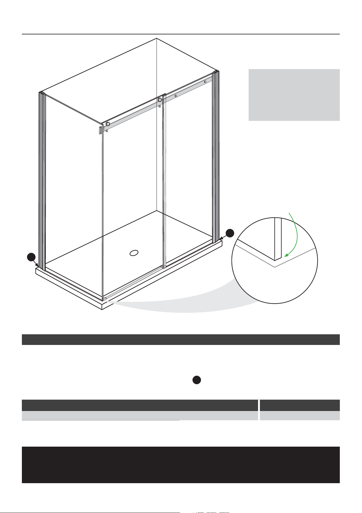
OPTION B: ANITA TILE SHOWER WITH PROFINISH TILE TRAY
1. Mark out the boundary line using the Minimum to Maximum table below. This will allow for walls leaning or
bowed inwards by 4mm.
2. Assess allowance for variances to plumb.
;OLIV\UKHY`SPUL^PSSIL[OL^HSSJOHUULSV\[ZPKLWVZP[PVU
4HYR[OLYL[\YUNSHZZWHULSSLHKPUNLKNLWVPU[HZWLYHKQHJLU[JPYJSLKKL[HPS
ANITA SHOWER: TILE WITH PROFINISH TILE TRAY - LAYOUT PLAN B
A
A
A
DOTTED LINE:
6<;,9*/(55,3)6<5+(9@305,
RETURN GLASS EDGE:
44)(*2-964+6;;,+305,
IMPORTANT DETAIL
NOTE: All measurements
HZZ\TL[OLÅVVYPZSL]LS
the walls are plumb and all
Z\YMHJLZHYLÅH[(U`]HYPH[PVU
T\Z[ILHKQ\Z[LKMVYPU[OL
measurements provided.
MINIMUM / MAXIMUM TABLE
Shower Type Front Door Panel (A) Min/Max Return Panel (B) Min/Max Profinish Tile Tray
1200 x 915 TT TT 1200X915
PENETRATION OF WATERPROOFING UNDER TILES
>H[LYWYVVÄUN^HYYHU[PLZHYLWV[LU[PHSS`]VPK^P[OWLUL[YH[PVUZVMTLTIYHUL)VUK^HSSWYVÄSLZ^P[O)VZ[PR=
4PUPT\TJ\YPUNOV\YZTT[VTT*\YPUNPZI`H[TVZWOLYPJTVPZ[\YLHIZVYW[PVUHWWYV_TTPUKH`Z
6
This is a brief overview of how to set up a door assembly only. This runs in conjunction with the general
instruction sheet.
Step 1,Z[HISPZOHUV\[LYIV\UKHY`SPULHJYVZZ[OLIHZLHUK\WLHJO^HSS\ZL[OLº:OV^LY3PUL[V;YH`,KNL»[HISL
HIV]L
Step 26U[OLZPKLVM[OLÄ_LKNSHZZMHZ[LU[OL^HSSJOHUULS[VIV\UKHY`SPUL
Step 37SHJLMYVU[Ä_LKNSHZZWHULSPU[V^HSSJOHUULS7S\TISLHKPUNLKNLVMNSHZZWHJRHZULLKLK
Step 4 Fix the rail (13) to the front glass (18)^P[OYHPSÄ_PUNZ (8)9LMLY[VKYH^PUNHUKKL[HPS)VUWHNL
Next Step To replicate the mounting point on the opposite side for the rail.
A:4LHZ\YL[OLYHPSWVZP[PVUIHJRMYVT[OLV\[LYIV\UKHY`SPULH[[OLÄ_LKNSHZZ^HSSLUK
B:4LHZ\YL[OLOLPNO[MYVT[OLIHZL[V[OLYHPSVU[OLÄ_LKNSHZZ^HSSLUK
C: Mark A and B on opposite side. Hold the level on the rail and double check the marked height.
NOTE: Have wall mounting 2mm lower to establish slight fall to shut position.
E:<ZL[OLYHPSQVPULYHZZLTIS` (14) to mark the two holes on the wall.
F:7YLKYPSS[OL^HSSHUKMHZ[LU\WQVPULYHZZLTIS`[VIV[O[OL^HSSHUK[V[OLYHPS
All other installation steps can be now followed in the general instructions eliminating the return panel details
that do not apply.
ANITA ALCOVE (DOOR ONLY) - LAYOUT PLAN C
NOTE: (SSTLHZ\YLTLU[ZHZZ\TL[OLÅVVYPZSL]LS[OL^HSSZHYLWS\TI
HUKHSSZ\YMHJLZHYLÅH[(U`]HYPH[PVUT\Z[ILHKQ\Z[LKMVYPU[OL
measurements provided.
OPTION C: ANITA ALCOVE (1200 DOOR SET) WITH TILE
)(:,(5+(*9@30*)(:,(7730*(;065:
The following table covers the Door Size with the Minimum
and Maximum Range. Care must be taken if using the
minimum or maximum measurements as discrepancies in
the walls or base may not allow for this.
SHOWER DOOR TYPE FRONT DOOR PANEL MIN/MAX
1200 Door 1151 - 1178mm
SHOWER LINE TO TRAY EDGE
Acrylic Tray 20mm
7YV-PUPZO;PSL;YH`/VI TT
7YV-PUPZOSL]LSLU[Y`[YH`H[[YHUZP[PVUSPUL:SVWLZ[HY[Z
Height
Depth
Dotted Line:
Outer boundary
Shower Line to Tray Edge
:LL;HISL
Rail Joiner:
Mounted on
door side
14
25
PENETRATION OF WATERPROOFING UNDER TILES
>H[LYWYVVÄUN^HYYHU[PLZHYLWV[LU[PHSS`]VPK^P[OWLUL[YH[PVUZVMTLTIYHUL)VUK^HSSWYVÄSLZ^P[O)VZ[PR=
4PUPT\TJ\YPUNOV\YZTT[VTT*\YPUNPZI`H[TVZWOLYPJTVPZ[\YLHIZVYW[PVUHWWYV_TTPUKH`Z
7
1.1 1.2
ANITA SHOWER - INSTALLATION INSTRUCTIONS
1.1
1. 2
2
TILE: )VUK[OL^HSSJOHUULSZ[V[OL[PSLZ^P[O)VZ[PR=YLMLYIHJR[V[PSLSH`V\[WHNLgre-penetration of
^H[LYWYVVÄUN
Acrylic:
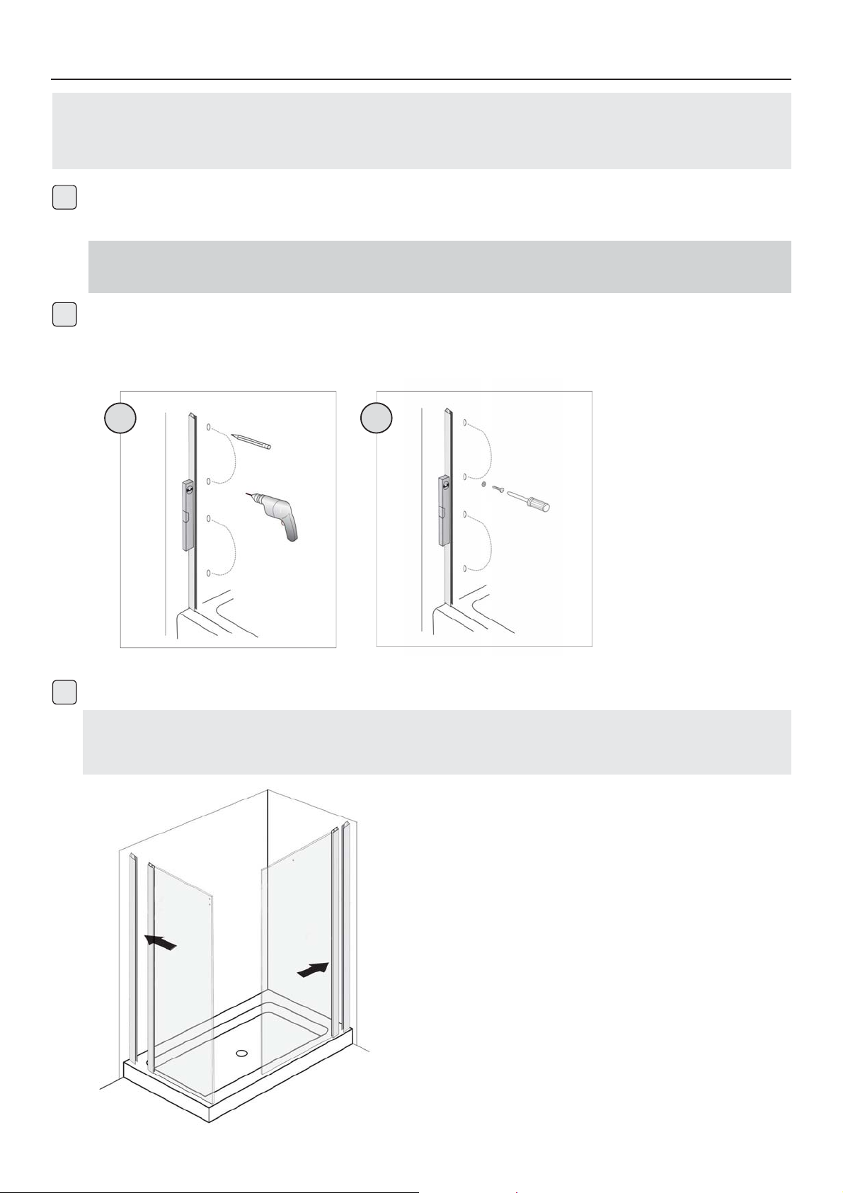
7YLKYPSSTTSLHKOVSLZPU[OL^HSSSPUPUNTH[JOPUN\W[V[OLJOHUULSOVSLZ
Acrylic:
(WWS`ZPSPJVUL[V[OLIHJRVM[OLJOHUULSHUKÄ_PUWSHJL^P[O[OL4_ZJYL^ZLUZ\YPUN[OH[[OL
channel remains plumb.
0UZLY[[OLYL[\YUWHULSHUKÄ_LKMYVU[WHULSPU[V[OL^HSSJOHUULSZ
TILING NOTE:7SHJLTT^PKL[OPUJSLHYWSHZ[PJZ[YPWZHZPZVSH[PVUWHJRLYZH[ KLNYLLZ\UKLY
[OLÄ_LKNSHZZ-PUHSS`ILMVYLÄUPZOPUN^P[OZPSPJVUL[YPT[OLL_JLZZ^P[OHRUPML
Identify the specific layout plan applicable to your specific shower. Use the correct
layout plan in conjunction with the installation instructions. Mark out the wall channels
taking into account the guidance notes.

8
3.1 3.2
3.3
B1
C1
RETURN
7(5,3
,5:<9,7(5,3:
REMAIN LEVEL
FIXED GLASS
-965;7(5,3
C1:
DOTTED LINE:
6<;,9*/(55,3)6<5+(9@305,
GLASS LINE:
44)(*2-964+6;;,+305,
16
15
14
17
A1
GLASS
RAIL
IMPORTANT DETAIL
3.1
3.2
3.3
0UZ[HSSYHPSIYHJRL[JVTWVULU[Z[VYL[\YUWHULS3L]LS\WIV[ONSHZZWHULSZHUKWHJR
to hold.
0UZLY[[OLYHPSPU[VYL[\YUNSHZZIYHJRL[HUKH[[HJOLK[V[OLMYVU[WHULS^P[O[OL[^VNSHZZÄ_PUN
WPLJLZHUK[PNO[LU[OLZL;PNO[LU[OLHSSLURL`ZVU[OLQVPULY[V[OLYHPS^OLU[OLYL[\YU
NSHZZPZH[ KLNYLLZVMM^HSS0MTVYLHKQ\Z[TLU[PZYLX\PYLKTV]L[OLNSHZZMYVU[WHULS^P[OPU[OL
wall channel.
The return panel leading edge is positioned 4mm back from the outer channel line as in the layout
WSHU7S\TI[OLNSHZZLKNLHUK[OLHZZLZZPM[OLHKQ\Z[TLU[PUVYV\[VM[OLYL[\YUWHULSPZULLKLK
As this effects the door running parallel at the bottom.
ENSURE A PLASTIC GLASS PROTECTOR IS USED BETWEEN ALL METAL PARTS AND THE GLASS

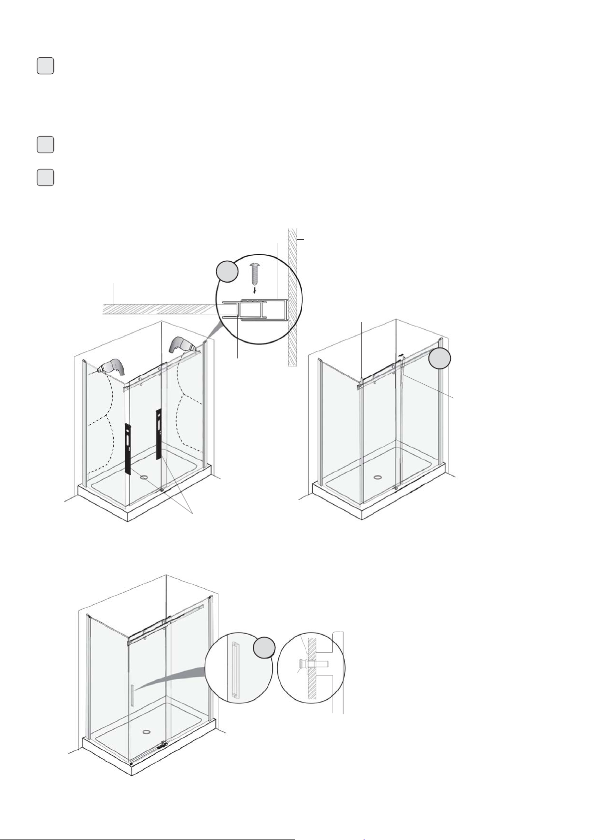
9
4.1
4.2
4.3
4.4
4.5
0UZ[HSS[OLYVSSLYZL[Z[VKVVYWHULS9VSSLYZZOV\SKILVU[OLV\[ZPKLVM[OLKVVY-P[^H[LY
KLÅLJ[VYVUIV[[VTLKNLVMKVVY
Hang the door on the rail from inside of the shower.
Carefully slide the door toward the return panel and check the gap between door and return panel
PZL]LU(KQ\Z[PMULJLZZHY`\ZPUNVMMZL[PUYVSSLYZVYHKQ\Z[TLU[MYVT[OLYHPSZ\WWVY[([[OPZWVPU[
assess if the return panel needs to go in or out slightly to align the door parallel to the tray.
)VUK^P[OZPSPJVUL[OLMVSSV^PUNWHY[Z[V[OL[YH`:SPKPUNISVJRZSV[[LKPU[V[OLNSHZZMYVU[WHULS
LKNLHUK[OL^H[LYIHYWVZP[PVULKWHYHSSLS[V[OLV\[ZPKLLKNLVM[OL[YH`NVPUNHJYVZZ[V[OLLUK
ISVJR HNHPUZ[[OLYL[\YUWHULS;HWLPUWVZP[PVUHUKHSSV^HTPUPT\TVMOV\YZMVY[OPZ[VJ\YL
0UZ[HSSSVJRPURUVIZVU[OLKVVY[PNO[LUYHPSÄ_PUNZ
4.5
4.1
4.2
4.3
4.4
WATER DEFLECTOR (19)
10
5.1
5.2
7S\TI[OLLUKZVM[OLNSHZZ6U[OLPUZPKLVMZOV^LYKYPSSTTOVSLZ[OYV\NOIV[O[OLÄ_LKWHULS
WYVÄSLZHUKPU[V[OL^HSSJOHUULSZ56;,!,UZ\YL[OH[[OLJOVZLUWVZP[PVUH]VPKZKYPSSPUN[OYV\NO[OL
NSHZZZLL+PHNYHT:JYL^[VNL[OLY\ZPUN4:JYL^Z*V]LY[OLZJYL^Z^P[OZJYL^JV]LY
JHWZ
0UZ[HSSSLHKPUNLKNLI\MMLYZ[YPWI\MMLYZLHS
0UZ[HSS[OLOHUKSLZL[^P[O[OLSVJRPUNZJYL^ZVU[OLPUZPKLVM[OLZOV^LY
5.3
-0?,+.3(::7(5,3
-0?,+7(5,3
796-03,
)<--,9:;907
)<--,9:,(3:;907:
,5:<9,.3(::7(5,3:
REMAIN LEVEL DURING
05:;(33(;065796*,::
CHANNEL WALL
5.1
5.2
5.3

Apply neutral cure silicon as indicated by dotted lines.
(JY`SPJ;YH`!5.:PSPJVULWSHZ[PJHKOLZPVU
• Tile Tray: Bostik V60
DO NOT USE SHOWER FOR 24 HOURS
Silicone is not used on the inside of the shower screen because water can build up over
time within the wall channel and leak out of the shower area. The screen is designed to
allow the water to return into the shower area, if any is present. SCREENS THAT ARE
SEALED ON THE INSIDE WILL VOID WARRANTY.
11
24 HOURS
6
www.newline.co.nz
This manual suits for next models
1
Table of contents
Other NewLine Shower Cabin manuals


