NewLine Rhine Pivot Series User manual

1. When you receive your Newline shower check contents for any freight damage.
2. Advise Newline on 0508 639 5463 if any damage has occurred or a defect
identied within 8 hours of receiving the goods so this can be rectied.
3. Do not proceed with installation until resolved.
Important!
May 2020
INCLUDES: 2-SIDED SHOWERS AND 3-SIDED ALCOVE DOORS
Rhine Pivot
Low Prole Tray Series
INSTRUCTION MANUAL

2
Page 3 Prep and layout tables for all pivot doors
Page 4 - 7 2-Sided shower
Page 8 - 12 3-Sided Alcove shower
NEWLINE RECOMMENDS A SKILLED TRADESMAN ACQUAINTED WITH
SHOWER INSTALLATIONS TO ENSURE THE VERY BEST OUTCOME.
PIVOT DOOR SETS 2-SIDED & ALCOVE APPLICATIONS
WARRANTY
Faulty goods are covered under warranty. Visit www.newline.co.nz for warranty information.
Breakages incurred during construction are not covered under warranty.
Installations must conform to the instructions to be covered by the warranty.
INSTRUCTIONS
Tray and liner instructions: Come with the specic tray supplied
Shower waste and supply fittings: Must be installed by a registered plumber.
HEALTH AND SAFETY
Toughened Glass:
• Do not rework precut glass panels. Cutting or altering a glass panel will cause it to explode without warning.
• Unpack all glass assemblies. Stand glass on soft packaging on the oor and against a wall. Care must be taken
not to strike any edge or corner against a hard surface as this will chip and destroy the glass panel.
Installation:
• Glass panels and assemblies are heavy. Two man lifting is recommend for handling and installation.
• Determine positioning of wiring and piping within wall cavities before shower installation. Mark their positions to
ensure electrical and piping areas are avoided.
• Wear appropriate protective clothing and eye protection during installation.
MATERIALS REQUIRED
Sika Silaex NG translucent silicone.
TOOLS REQUIRED
AFTERCARE
The shower must be squeegeed down after each shower. Thoroughly clean weekly with a microber cloth, mild
detergent and water. Rinse with clean water and squeegee and wiped dry.
NOTE: ACRYLIC TRAY & LINER - Detailed Instructions for both are packed with shower tray.
INDEX
3
BEFORE YOU START: READ NOTES OF TABLE A & B LAYOUTS
Check TABLE A for layout of 2-Sided shower
• Identify the size of shower you are working with.
• The door set has shared adjustment points: Wall and corner post positions.
• Walls bowed or leaning inwards: Check adjustment available and use Min to Max Table B if your case requires
this.
Note: 3-Sided shower table is on page 9.
2-Sided Shower: Ensure the oor is level and the walls are plumb and at.
Position all framing for solid xing for the shower tray, shower and plumbing ttings. Wall proles
require a stud centred 20mm back from tray outside edge.
Ensure all plumbing items have been installed prior to the lining being attached.
Alcove Shower: The shower tray must be a rm t to the framing prior securing the walls. Floors
must be level and at. Walls also must also be plumb and at. Two walls multiply errors and limit the
potential to t the acrylic liner and shower screen.
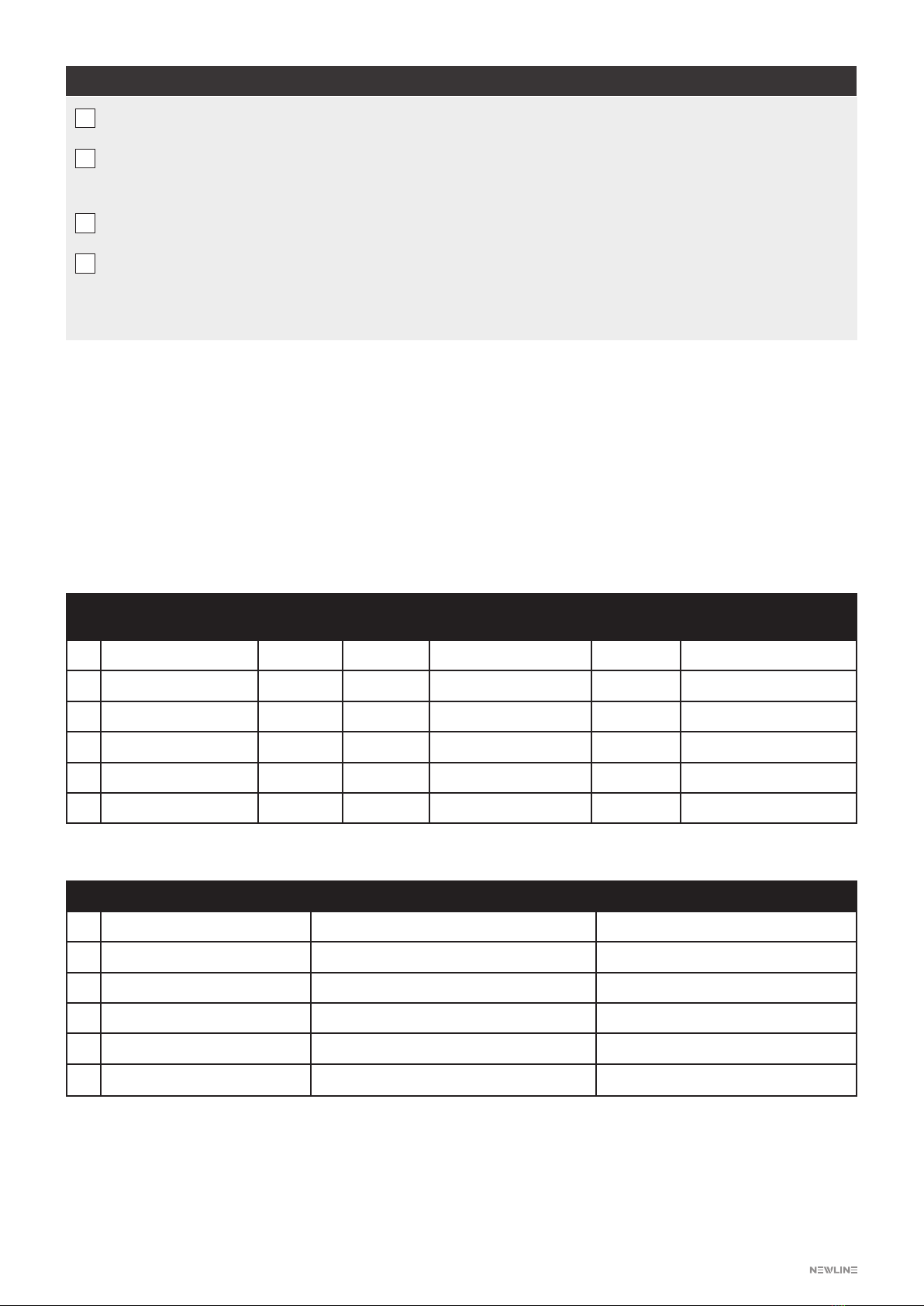
PREPARATION CHECKLIST
DOOR SET
TRAY SIZE
CORNER
POST
ADJUSTMENT
WALL
ADJUSTMENT RETURN PANEL
TRAY SIZE
WALL
ADJUSTMENT TRAY EDGE TO WALL
CHANNEL
1 750mm 0 2 915mm 17 15mm
2 820mm 5 10 820mm 413mm
3915mm 6 13 750mm 4 13mm
4915mm 0 11 915mm 11 21mm
51000mm 0 4 1000mm 4 13mm
61200mm 0 2 915mm* 12 20mm
DOOR & RETURN DOOR SET RETURN PANEL
1 750mm x 900mm Min 720mm — Max 740mm Min 870mm — Max 888mm
2820mm x 820mm Min 778mm — Max 794mm Min 790mm — Max 805mm
3900mm x 750mm Min 870mm — Max 890mm Min 720mm — Max 738mm
4900mm x 900mm Min 870mm — Max 890mm Min 870mm — Max 888mm
51000mm x 1000mm Min 970mm — Max 990mm Min 970mm — Max 988mm
61200mm x 900mm Min 1165mm — Max 1185mm Min 870mm — Max 888mm
Walls out of plumb will not allow for full Max/Min options.
TABLE A: LOW PROFILE TRAY 40mm High
TABLE B: MIN TO MAX PIVOT SHOWER RANGE (LH column number ties up to Table A)

4
11
09
10
12
12
Wall Channel K7119 Back Door Seal K7072 Back Door Seal Stop
K4000
Pivot Block K2004
Handle
Replacement Screw Pack - 2 & 3-Sided Chrome & White K2271
4x35mm Screws Screw Caps 4x10mm screwsWall Plug (Concrete)
Return Panel 1200 Door
All doorsexcept1200
Lower door seals
K6808
20 PCS8 PCS8 PCS 12 PCS
PIVOT 2-SIDED SHOWER
COMPONENT LIST

5
1
Apply silicone
bead down back
of channel prior to
fastening.
Mark wall prole.
Acrylic Shower Layout
Ensure you read
“BEFORE YOU START”
section on page 3.
Refer to Page 3
Table A & B will give
measurements for your
specic installation.
B
Fasten wall proles for return and
door panels.
A

6
2
Fit return panel.
12
A
• Connect door set to
return panel.
• NOTE: Table on page
3 will show suggested
corner post position for
your specic shower
install.
• Fasten this join parallel
at corner.
• Corner post must be
plumb for alignment of
magnetic seal.
B
• Finally adjust shower door in wall
proles and square up door to
frame.
• Drill and fasten door frame and
return panel to wall proles.
3B
Ø3.2mm
A

7
4
5
Apply silicone to
join as indicated.
Seal the join
between wall prole
and frame. 150mm
up from base on
both sides.

8
4x35mm Screws Screw Caps
16 PCS
4x10mm screws
Lower Door Seals
K6808
Wall Plug (Concrete)
Replacement Screw Pack - Chrome & White K2271
Wall Channel K7102 Back Door Seal K7072 Back Door Seal Stop
K4000
Pivot Block K2004
Handle
1200 Door
All doors except 1200
8 PCS 8 PCS 8 PCS
09
07
08
10
PIVOT 3-SIDED ALCOVE SHOWER
COMPONENT LIST: 3-SIDED ALCOVE

9
Wall Channel Adjustment: Pivot 3-Sided Alcove Shower Table
Includes Low Prole (L/P) Tray applications
Walls out of plumb will not allow for full minimum / maximum
options.
1
Fit seal to back of door
channel and fasten
end caps (04) to top
and bottom.
Back of Door
Position of wall proles to
door frame.
2
NOMINAL TRAY
SIZE
TRAY TYPE TRAY ACTUAL WIDTH
(+/- 1mm)
LINER TO LINER
MEASUREMENT
SCREEN MIN-MAX EXTENSION AT WALL
2-SIDES OF FRAME
810 L/P 812mm 786mm 769mm - 784mm 8.5mm
900 L/P 902mm 876mm 860mm - 890mm 8mm
1000 L/P 1002mm 976mm 960mm - 990mm 8mm
1200 L/P 1202mm 1176mm 1155mm - 1185mm 10.5mm
04

10
3
Layout
Mark wall prole holes both sides.
Predrill liner with 2mm bit.
B
A
Fasten wall proles.
Apply silicone
bead down back
of channel prior
to fastening.
08
09

11
4
5
Fasten door frame to wall proles. Door seal full width of door. Notch out
glass ange by 12mm each end of door.
Trim each side of pivot.
1. Plumb and square up door to frame.
2. Adjust evenly to both wall proles.
08
09

12
6Apply silicone to outer join as indicated.
Seal the join between
wall prole and frame,
150mm up from base
on both sides.
CONTACT
Freephone: 0508 639 5463 Phone: 09 444 2053 Fax: 09 443 0044
Email: [email protected] www.newline.co.nz
Table of contents
Other NewLine Shower Cabin manuals


Popular Shower Cabin manuals by other brands


ERLIT
ERLIT Eclipse ER 5709P Installation and operation instruction

Omnires
Omnires Bronx S2050 Installation and maintenance instructions

MAAX
MAAX K3131-B installation instructions

Sanotechnik
Sanotechnik PR150 Mounting instruction

OVE
OVE EMILY SWIFT 36 instruction manual

Dreamline
Dreamline ENIGMA-X installation instructions


