EINBAUANLEITUNG – DEUTSCH – P16
INSTALLATION
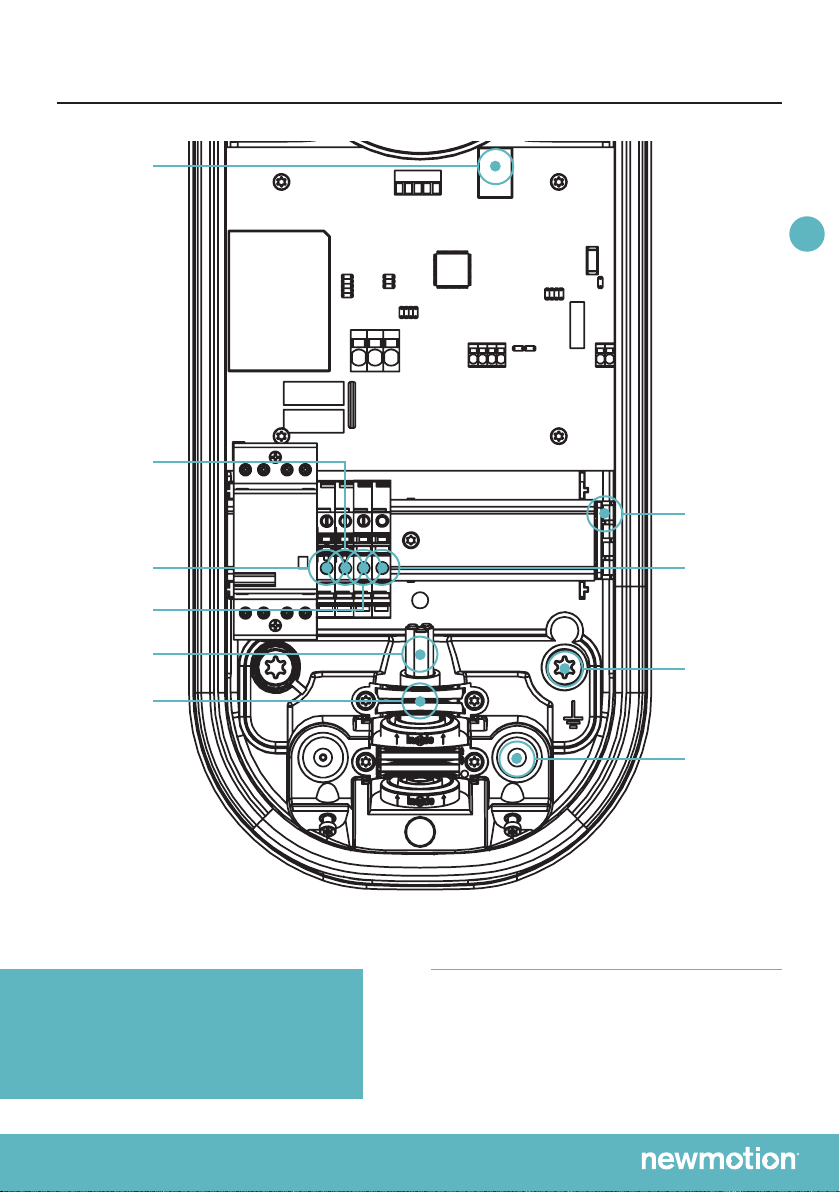
SCHRITT FÜR SCHRITT
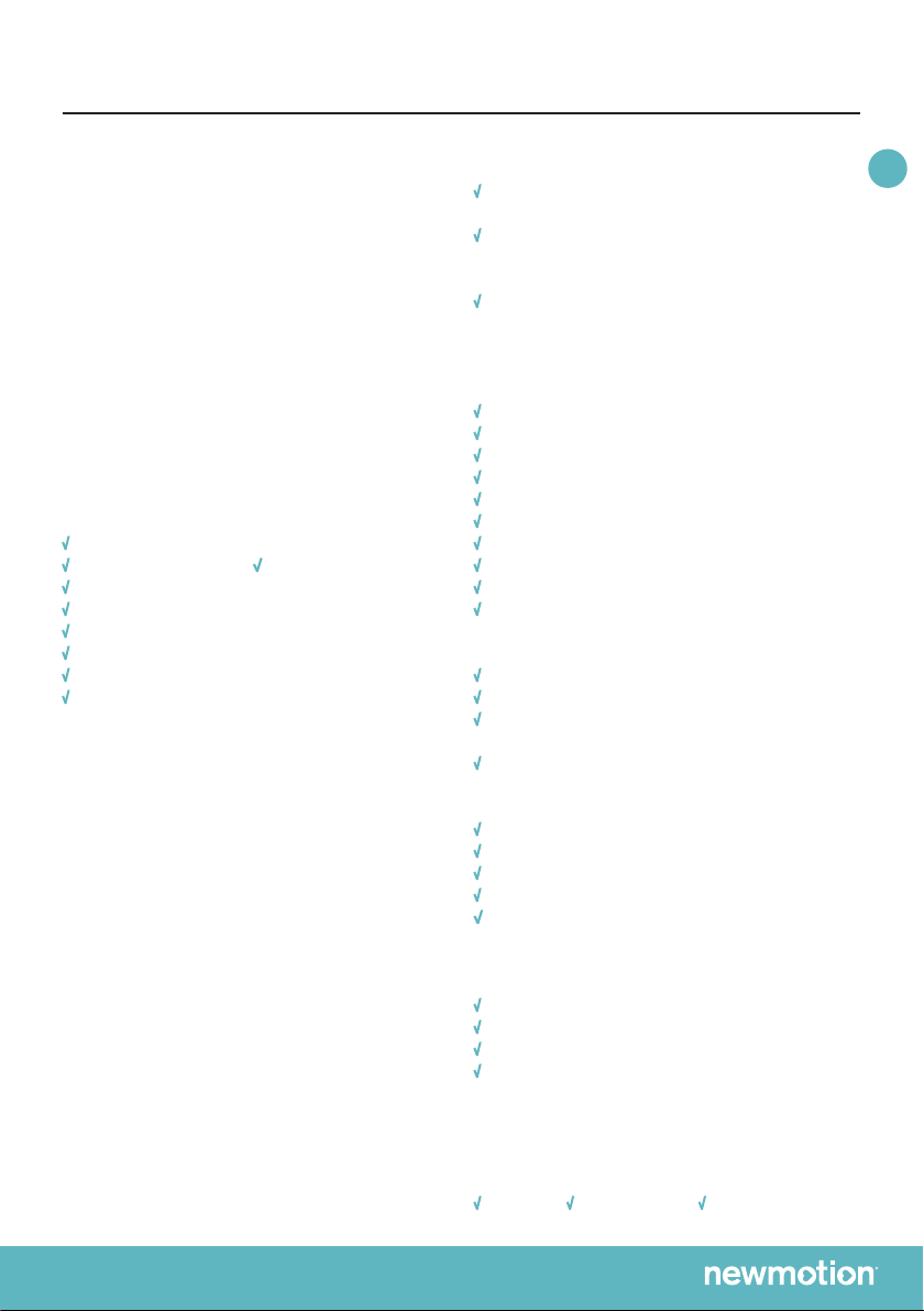
1. Bereiten Sie je nach der Entfernung die Verkabelung vor
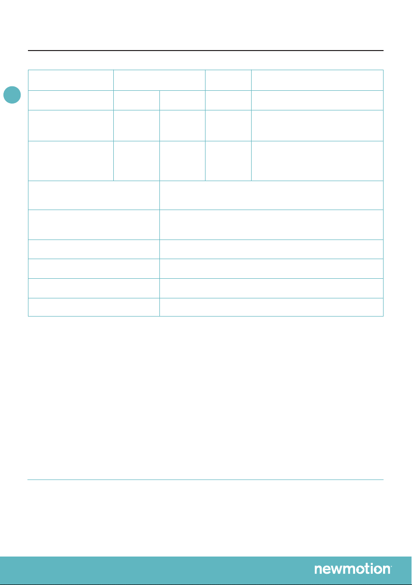
(siehe„SpezikationenzurInstallation“indieserAnlei-
tung).
2. Befestigen Sie den Wandbügel auf der gewünschten
Höhe (+/- 1 Meter) an der Wand.
3. Drehen Sie die Steckdose/Steckdosenattrappe
linksherum aus dem Gehäuse der Ladestation.
Zum Öffnen der Ladestation ziehen Sie anschließend
kräftig an dem Gehäuse vom hinteren Teil. Verwenden
Sie hierbei keine Hilfsgegenstände.
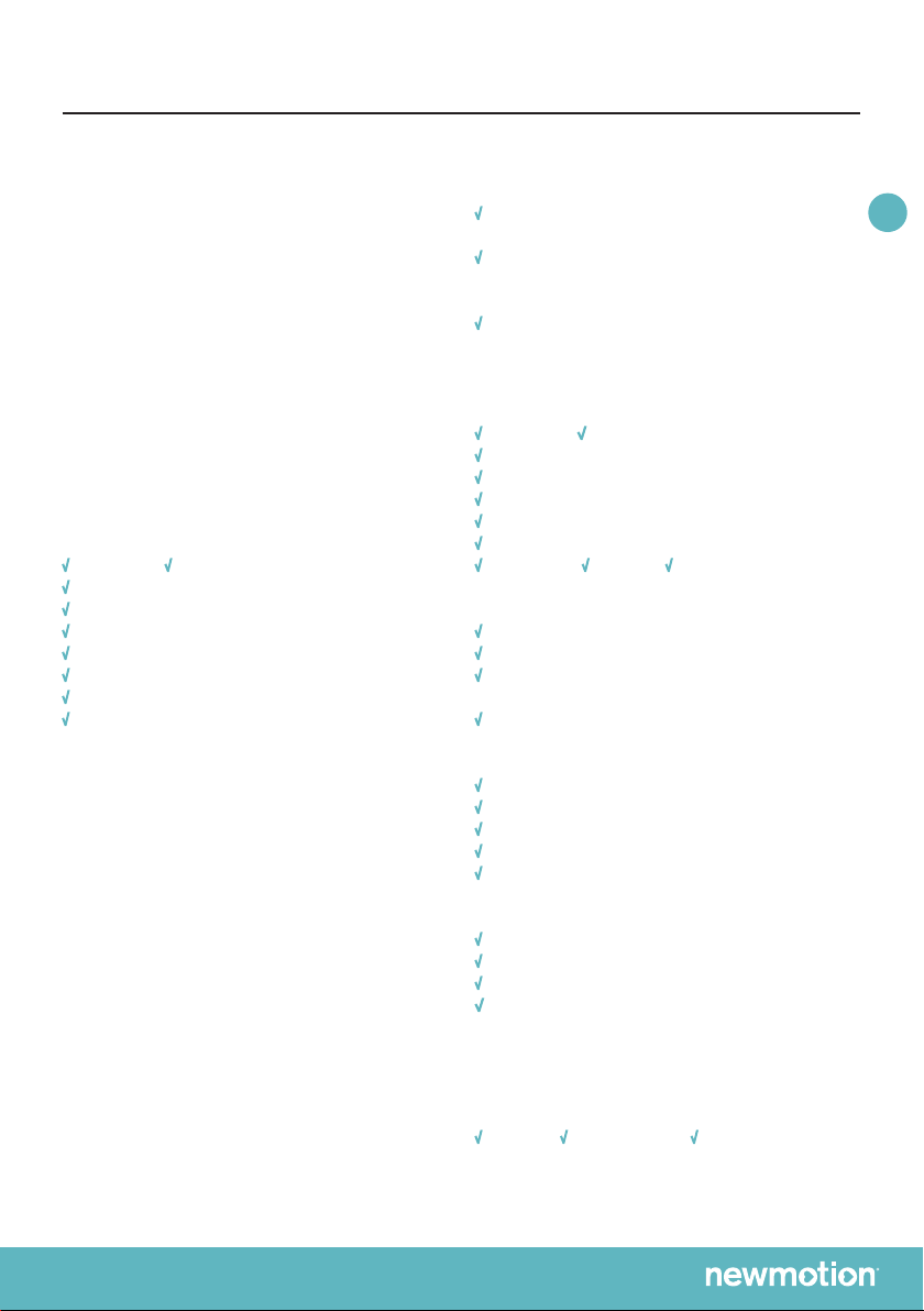
4. Platzieren Sie die Ladestation probehalber am
Wandbügel. Zeichnen Sie die beiden unteren
Befestigungspunkte der Ladestation an der Wand an
und verwenden Sie passendes Befestigungsmaterial
(Dübel, Schrauben und Unterlegscheiben).
5. Befestigen Sie die Ladestation mit 2 mitgelieferten
M8 x 12 mm-Bolzen und Unterlegscheiben am Wand-
bügel. Montieren Sie die Ladestation anschließend
mithilfe der beiden unteren Befestigungspunkte an
die Wand. Achten Sie darauf, dass sich die grauen
Distanzstücke an der Rückseite der Ladestation an
denbeidenunterenBefestigungspunktenbenden.
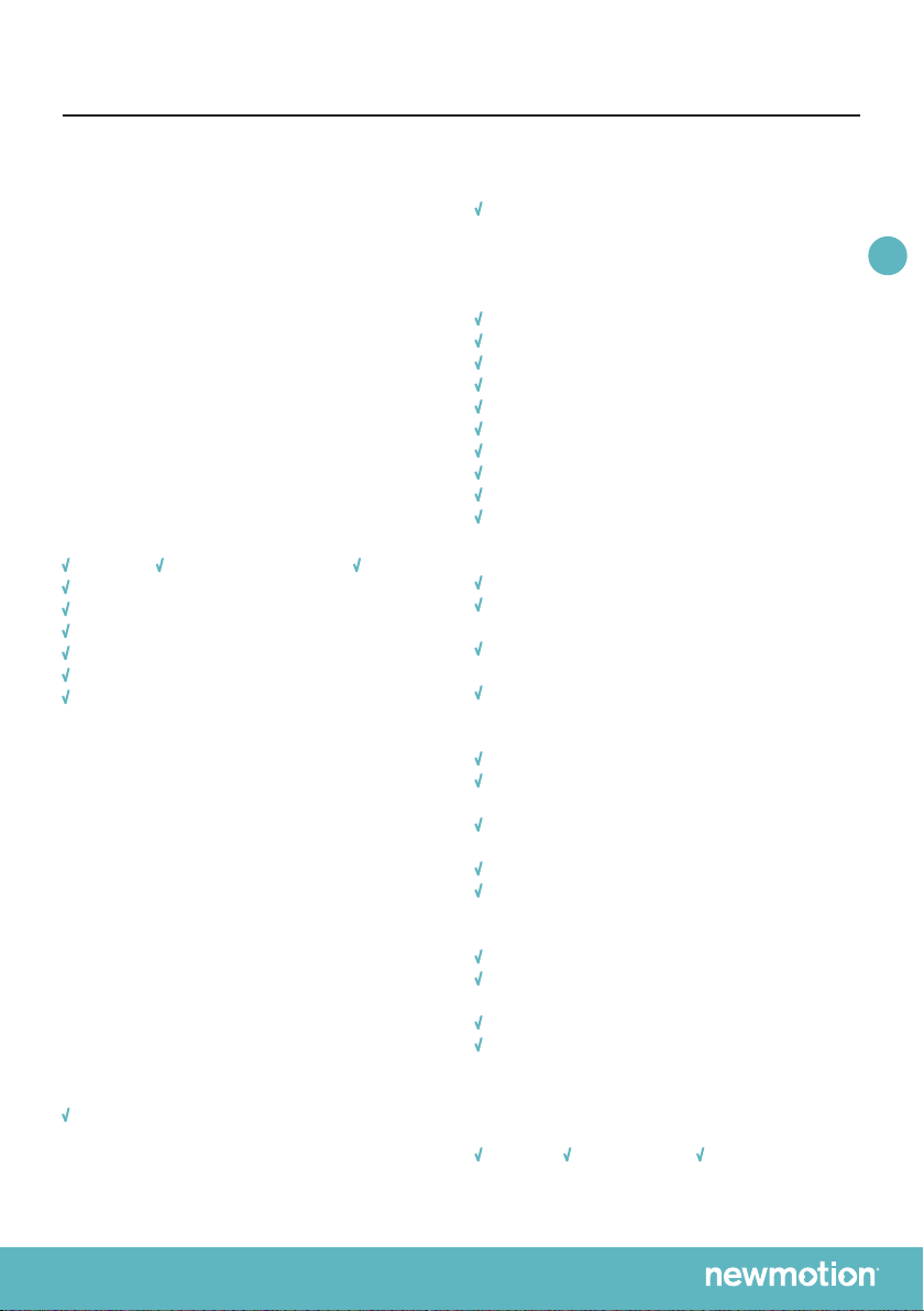
6. Wählen Sie je nach Dicke des Kabels das richtige
Format der Durchführtülle aus und platzieren Sie diese
auf der Öffnung der Netzkabeldurchführung. Feuchten
Sie diese ggf. leicht an, damit ein problemloses
Durchführen des Netzkabels möglich ist.
7. Schließen Sie das Netzkabel an und befestigen Sie es
mit der Kabelklemme. Befestigen Sie das Erdungska-
bel auf der gelb-grünen Reihenklemme, den Nulldraht
auf der blauen Reihenklemme und den Leitungsdraht
auf der grauen Reihenklemme.
8. Befestigen Sie die schwarze Durchführtülle auf der
Öffnung neben der Durchführung des Netzkabels,
um die Ladestation wasserdicht abzuschließen. Bei
der Verwendung eines festen Ladekabels ist dies nicht
erforderlich.
9. Wichtiger Hinweis bei der Verwendung eines festen
Ladekabels: Wählen Sie je nach Dicke des Kabels das
richtige Format der Durchführtülle aus und platzieren
Sie diese auf der Öffnung der Ladekabeldurchführung.
Schließen Sie den Netzanschluss des festen Ladeka-
bels an die dafür vorgesehenen Federklemmen links in
derLadestationanundxierenSiedasKabelmithilfe
der Kabelklemme. Schließen Sie das Kabel, wie im
Anschlussplan beschrieben, an den Verbindungs-
stecker “Anschluss für die Kommunikation mit dem
Auto”.
10. Wichtiger Hinweis bei der Verwendung einer Ethernet-
verbindung: Führen Sie das UTP-Kabel durch die
Gummiabdichtungskappe der Durchführung für
Datenkabel und schließen Sie diese an den Etherne
tanschluss an. Rufen Sie NewMotion an, um die
Ethernet-verbindung zu aktivieren:
+49 (0) 30 215 028 48.
11.Wichtiger Hinweis bei der Montage am Pfahl: Erden
Sie den Pfahl mithilfe des Erdungskabels über den
Befestigungsbolzen rechts unten in der Ladestation
(siehe Erdungszeichen).
12. Schließen Sie das Netzkabel an den Zählerkasten an.
13. Setzen Sie die Ladestation unter Spannung
(Ladestation-Start).
14. Prüfen Sie, ob die Ladestation mit dem Netzwerk
verbunden ist. Diese Prüfung kann schnell über
chargeportal.newmotion.com/test erfolgen. Geben
Sie im Suchfeld die Seriennummer ein und klicken Sie
auf „Search“ (Suchen). Nun sollte „Online“ hinter der
Seriennummer angezeigt werden. Ist dies nicht der
Fall?KontrollierenSiedannerst,obdieLadestation
korrekt angeschlossen wurde und führen Sie danach
die Prüfung nochmals durch. Wenden Sie sich bei
anhaltenden Problemen an NewMotion:
+49 (0) 30 215 028 48.
15. Befestigen Sie das Gehäuse an der Ladestation.
Bringen Sie die 4 mitgelieferten M4 x 12 mm-Bol-
zen ringsum so an der Fassung an, dass die Kappe
bündig mit dem Gummi abschließt, das Gummi aber
nicht verformt. Befestigen Sie anschließend die anderen
2 mitgelieferten M4 x 12 mm-Bolzen an der Unterseite
des Gehäuses.
16. Drehen Sie die Steckdose/Steckdosenattrappe in das
Gehäuse rechtsherum und verriegeln Sie diese mit
dem mitgelieferten M4 x 20 mm-Bolzen. Ziehen Sie
den Bolzen fest, aber nicht zu fest, an.
17. Kleben Sie die entsprechenden mitgelieferten
Aufkleber (1-phasig oder 3-phasig) auf die Seiten der
Ladestation in die hierzu vorgesehenen Aussparungen.
18. Geben Sie im Sicherungskasten an, auf welchen
Gruppen die Ladestation installiert ist.
NL EN DE FR