newmotion Home Advanced Edition 7 User manual
100 cm
Home Advanced Edition 7
Home Advanced Edition 11
INSTRUCTION MANUAL – EN
VERSION 07A0RNM20ENG05 2020


INSTALLATIEHANDLEIDING – P3 VERSION 0129NM02INT01INSTRUCTION MANUAL – P3 | P3 07A0RNM20ENG05
1.1 PRODUCT DESCRIPTION &
INTENDED USE
Thank you for choosing a NewMotion Electric Vehicle
(EV) Charge Point.
This charge point is intended to charge the batteries within
EVs compatible with IEC-61851 MODE3 denition and
requirements. Dedicated EV specic plugs will need to be
utilised. No adaptors, conversion adaptors or extension
sets for cables are allowed to be used. EVs and cables
used with this charge point should always be undamaged
and in their original state.
1.2 SAFETY WARNING + CAUTION!
The electrical system must be voltage-free during the
entire installation procedure. Failing to do so can lead to
serious injury or even death. The installation procedure
must be carried out by a trained installer who works in
accordance with all relevant local laws and regulations.
Do not install in potentially explosive atmospheres and/
or zones with high electromagnetic radiation and/or in
ood-prone areas.
The charge point is connected to the electricity grid and
even if the equipment is switched o, hazardous voltag-
es may be present at the input terminals. Always switch
o the AC supply before starting any work on the charge
point and/or its installation. Do not carry out any work
in rainy conditions or when the humidity is above 95%.
The safety guidelines are intended to ensure correct in-
stallation and usage. Any failure to comply with the valid
safety guidelines or instructions provided in this manual
may result in re, electrocution or severe injury.
The charge point is a product in Safety Class I and is
supplied with an earth terminal for protection purposes.
The AC input clamps must be tted with an uninterruptible
earth for protection purposes. Ensure that the connection
cables are tted with fuses and circuit breakers. Never
replace a protection component with another type. First
check the full installation to determine if that component
can be used with the existing installation components.
Before you switch on the charge point, check that the
available power source matches the conguration set-
tings of the product, as described in this manual.
Tripping of the RCD could be caused by an earth fault
or a defect relay. If, after resetting the RCD, the device
cannot be activated or immediately trips again; please
contact your installer.
1.3 LEGAL DISCLAIMER
This manual is created for you with care.
We however do not guarantee that all information is
complete, accurate and correct.
If you nd any unclarities or mistakes in this installation
manual, or if you have any feedback or suggestions in
general about this manual, please inform us at
installationmanualfeedback@newmotion.com and men-
tion the document version in the subject.
Please check the website
go.newmotion.com/renaultinstallation
for the latest version of this manual.
NewMotion strongly advises to have the product
installed by EV-Ready certied professionals. How the
product should be installed and used depends on local
circumstances and local and national regulation, which
are not mentioned in our manual. NewMotion is not
responsible for any loss or damage whatsoever caused
– including without limitation, any indirect, personal or
consequential loss or damage – arising from or in con-
nection with the use of this manual. Nor does
NewMotion accept any liability for any such loss or
damage arising out of your reliance on any information
contained in this manual.
1. INTRODUCTION

INSTALLATIEHANDLEIDING – P4 VERSION 0129NM02INT01INSTRUCTION MANUAL – P4 | P4 07A0RNM20ENG05
This selected charge point can be connected to a Charge
Point Operator (CPO) backoce via WiFi or ethernet.
In case of an error or issue, on site support is needed
from a ZE-Ready certied installer. Your Renault dealer
should be able to provide you a list of ZE-Ready certied
installers.
2. CHARGE POINT OPERATION

INSTALLATIEHANDLEIDING – P5 VERSION 0129NM02INT01INSTRUCTION MANUAL – P5 | P5 07A0RNM20ENG05
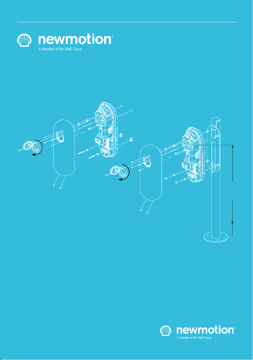
Wall mounting
Installation materials
Installation &
conguration of
accessories
Required tools & additional materials
(not provided)
- 4x 6.3mm x 70mm Self Tapping pan
head Torx screws (DIN 7981C) stainless
steel (A4);
- 4x plugs;
- 4x Stainless steel (A4) washers;
- Drill and bit;
- Torx screwdrivers (T20);
- Voltage tester;
- Tape measure;
- Spirit level
- Power cable;
- Cable mount clips;
- RCD & MCB;
- For local conguration, a smartphone
with Installer App
- For EV- and ZE-Ready installation:
Cable 5 x Ø 1,5mm2 (minimum) for shunt
and ON/OFF peak accessories;
- Cable mount clips;
- UTP cable (CAT5 or CAT6);
- RJ45 UTP cable crimp tool;
- RJ45 connectors;
- Network cable tester;
- For Load Shedding functionality:
- RJ12 cable (straight) for Load Shedding
module connection;
- Free schuko socket in fuse box for power
supply of Load Shedding module;
- Shunt 3 options:
> ABB S2C-A2 in combination with S200
MCB or DS200 RCD
> Schneider IMX A9A26946 in
combination with ACTI9 RCD or MCB
> Legrand DX3 shunt trip (406278) in
combination with DX3 RCD or MCB
Package contents with charge point
- Charge point;
- Rubber grommets (various sizes);
- 2x Plastic spacers;
- 1x M4 x 16 mm bolt (Torx);
- 6x M4 x 12 mm bolts (Torx);
- 2x Power cable clamps;
- 2x UTP data cable inlet with rubber seal
- Load Shedding module for Load
Shedding functionality;
- P1 dongle for Load Shedding
functionality (black);
- QR code for WiFi connection
3. PRODUCT OVERVIEW
3.1 MOUNTING, PACKAGE CONTENTS AND REQUIRED TOOLS

INSTALLATIEHANDLEIDING – P6 VERSION 0129NM02INT01INSTRUCTION MANUAL – P6 | P6 07A0RNM20ENG05
3.2 TECHNICAL SPECIFICATIONS
3. PRODUCT OVERVIEW
CONTINUED ON NEXT PAGE
Serial number format Home Advanced 7
Serial number format Home Advanced 11
Maximum charge capacity
Standard congured charge capacity
Electric safety category
Connector type
Dimensions (H x W x D)
Weight
Standard colours
IEC-62262 IK code (robustness)
IEC-60529 IP code (protection class)
Certicates
kWh measurement & meter part number
User interface
Identication
Communication backoce
Communication Load Shedding module
07A _ _ _ _ _
07B _ _ _ _ _
Home Advanced 7: single phase 32A*
Home Advanced 11: triple phase 16A*
Home Advanced 7: 3,7 kW - single phase 16A**
Home Advanced 11: 11 kW - triple phase 16A**
Class I
Type 2S - socket with shutter
503.5 x 200 x 137 mm
± 4.5 kg
Rear side RAL 7031 (grey)
Front side RAL 9010 (white)
IK10
IP54*** (for indoor and outdoor use)
IEC-61851-1
IEC-61851-22
EV-Ready 1.4G1 & ZE-Ready 1.4G1
IEC-62262 -> IK10
IEC-60529 -> IP54
MID certied
LED
Plug & Charge (standard congured)
RFID (NFC) Mifare 13.56 MHz (via local conguration)
IEC 14443A
IEC 14443B
Ethernet connection (DHCP, TCP 443, TCP80, TCP21)
WiFi - 802.11 (2,4 GHz)
Straight wired RJ11 or RJ12 (6P6C) connectors on
CAT5 cable (max 100 mtr)

INSTALLATIEHANDLEIDING – P7 VERSION 0129NM02INT01INSTRUCTION MANUAL – P7 | P7 07A0RNM20ENG05
* The maximum charge capacity of the charge point depends on several factors. This includes: local rules & regulations,
the type of EV, the grid connection at your location and the electricity usage of your building;
** Use the conguration software in order to change the charge capacity (only on site - locally - possible by an installer);
*** The charge point shall not be exposed to direct water jets or cleaned with high water pressure devices. The charge
point shall not be installed outdoors with a road proximity less then 5 meters.
3.2 TECHNICAL SPECIFICATIONS (CONTINUED)
3. PRODUCT OVERVIEW
P1 DONGLE SPECIFICATIONS
Backoce protocol
Stand-by consumption
Operating temperature range
Operating humidity range
Operating air pressure range
Maximum mounting height socket
Advised mounting height socket
Mounting position
Function for ventilation according to IEC-61851
Conguration
OCPP protocol
3-5W
-30℃ to +50℃
5% to 95%
860 hPa to 1060 hPa
1.5 meter above ground
1 meter above ground
Vertical and upright postion only
Not supported
Local conguration using the Installer App on a
smartphone
Dimensions
Weight
Required input
Operating humidity range
Operating temperature range
Certicates
Enclosure of the electrival cabinet requirement
55x25x30 mm
27 gr
5V DC - 100mA
5-95%
5-55 °C
CE
IEC6236 8-1:2014
Immunity according to EN 61326-1:2013
Must be able to resist a force of 250N
INSTALLATIEHANDLEIDING – P8 VERSION 0129NM02INT01INSTRUCTION MANUAL – P8 | P8 07A0RNM20ENG05
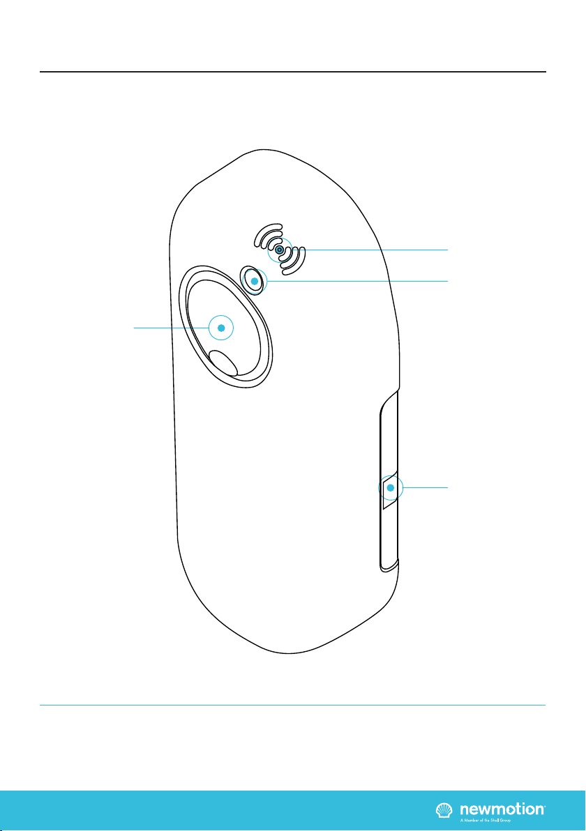
3.3 OVERVIEW OF PRODUCT
3. PRODUCT OVERVIEW
Type 2S shutter
EV Plug socket &
Cover lid
RFID Reader
Identication label
with serial number
LED Status indicator
INSIDE
INSTALLATIEHANDLEIDING – P9 VERSION 0129NM02INT01INSTRUCTION MANUAL – P9 | P9 07A0RNM20ENG05
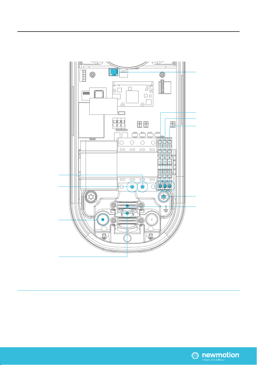
3. PRODUCT OVERVIEW
3.4.1 OVERVIEW OF CONNECTIONS
Ethernet port
Earthing pole
UTP data cable inlet
with rubber seal
Inlets for
power cables
Power cables
clamps
Phase 2
Phase 3
Phase 1
Neutral
Earthing

INSIDE
INSTALLATIEHANDLEIDING – P10 VERSION 0129NM02INT01INSTRUCTION MANUAL – P10 | P10 07A0RNM20ENG05
3. PRODUCT OVERVIEW
3.4.2 OVERVIEW INSTALLING ACCESSORIES
5 wires Ø 1,5mm2
accessories cable inlet
Cable clamp
ON/OFF Peak
connection
(L2 & L3 from
accessories cable)
P1 Port
for Load Shedding
Shunt connection
(L1 & N from
accessories cable)
UTP data cable inlet
with rubber seal for
Load Shedding

INSTALLATIEHANDLEIDING – P11 VERSION 0129NM02INT01INSTRUCTION MANUAL – P11 | P11 07A0RNM20ENG05
Wiring advice*
Power cable size
Earthing advice*
Required nominal
input voltage at
charge point
MCB
RCD
Ethernet connection
cable requirements
Load Shedding cable
requirements
5 wires Ø 1,5mm2
accessories cable
Ø 10mm - Ø 22,5mm
10 mm2solid wire
6 mm2stranded wire with ferrules
PE-cable (PEN conductor is not allowed)
Separately installed grounding electrode
< 100 Ohm spreading resistance
230V+N +/-10% 50Hz
400V (3 x 230V+N) +/-10% 50Hz
Cable grommets sizes
Maximum cable terminal block
TN-system
TT-system
Single phase
Triple phase
4. INSTALLATION DETAILS
The installer is responsible for selecting a cable thickness & safety components appropriate for
the specic situation and according to local regulations
* The installer is always responsible for selecting a cable thickness appropriate for the specic situation and
according to local regulations;
** The installer must select a suitable MCB with C-characteristic to match the amperage setting of the charge point,
taking into account MCB manufacturer specications and EV-Ready guidelines;
NOTE: The charge point can be set between 16 A / 20 A / 25 A and 32 A (depending on version)
- Wire for the maximum hardware amperage under continuous load;
- Calculate with a COS-Phi of 0.8;
- Calculate with a max allowed voltage drop over the cable of 2%;
- Use shielded cable for underground wiring
C-characteristic**
30mA Type B, or 30mA Type A (Hi, Hpi, Si) in combination with appropriate
equipment that guarantees shutdown of power when a DC leakage of more than 6mA
occurs
Standard CAT5 or CAT6 Ethernet cable (UTP cable with RJ45 connectors)
Straight wired RJ11 or RJ12 (6P6C) connectors on CAT5 UTP cable (max 100m)
- L1, L2, L3, N + PE;
L1 & N for connecting the shunt
L2 & L3 for connecting the ON/OFF Peak signal
- Always connect PE to terminal blocks of charge point and at distribution board
- Use shielded cable for underground wiring;

INSTALLATIEHANDLEIDING – P12 VERSION 0129NM02INT01INSTRUCTION MANUAL – P12 | P12 07A0RNM20ENG05
Thank you for installing this charge point. Make sure
there is enough space to properly do the work.
Ensure to work safely and take the safety of others into
consideration as well, always work according to local
safety regulations. Ask the owner if there is anything
of signicant importance that requires electricity in the
house, before you turn of the electricity.
When selecting the mounting location of the charge point,
ensure that future maintenance work can be carried out
safely without obstruction.
5.1 PREPARATION
Step 1: Prepare the cabling & RCD and MCB (conform to
local rules & regulations);
Step 2: Indicate which circuit in the distribution board is
connected to the charge point;
Step 3: Turn the socket lid anti-clockwise and out of the
cover of the charge point;
Step 4: Then pull the cover from the rear edge to open
the charge point. Do not use any objects or tools to do
this
5.2 MECHANICAL MOUNT
Step 1: Put the charge point back plate on the wall to
check its positioning (connector at +/- 1 m height). On
the wall, mark the positioning of the top two and bottom
two attachment points of the charge point and select the
appropriate xtures (plugs, screws and washers);
Step 2: Drill all four holes and put the plugs in place;
Step 3: Secure the charge point to the wall using the top
two and bottom two attachment points. Ensure that the
rubber and stainless steel washers are used are placed
on the back of the charge point at the bottom two
attachment points
5.3 POWER CONNECTION
Step 1: Select the appropriate grommet(s) that suits
the cable(s) thickness and place it in the opening of
the power cable inlet. Lubricate if necessary to make it
easier to feed the power cable through;
Step 2: Secure the power cable(s) using the cable
clamp(s);
Step 3: Connect the power to the terminal blocks, as
indicated in section ‘3.4.1 Overview of Connections’.
Warning: Keep charge point switched o during
installation!
5.4 LOAD SHEDDING MODULE
The Load Shedding Module package contains one Load
Shedding module, one power adapter and three current
transformers (CT’s). The CT’s must be connected at
the most upstream point of the house grid, closest to
the grid connection. Arrows are shown on the CT, but
direction is not important.
The connections for the CT’s are located at the bottom
of the Load Shedding module, and are labelled with
L1, L2 and L3 on the front label. L1, L2 and L3 must be
connected to the rst, second and third phase of the
house grid in the correct order.
Although each measuring head is provided with two
dierent coloured threads, the polarity of connection is
not important.
The power cable connection on the terminal block of
the charge point should match the L1, L2 and L3 in the
charge point.
For a 1 phase installed charge point the L1 measurement
head should match the conduction which is connected
to the L1 of the terminal block.
Installation procedure
Step 1: Install the Load Shedding module on the DIN Rail
in the fuse box;
Step 2: Connect the CT(’s) to the Load Shedding
module, as described in the beginning of this paragraph;
Step 3: Apply the CT(’s) to the grid connection(s). Make
sure to apply the CT(’s) so that the total power usage of
the household is measured on each phase;
Step 4: Connect the power adapter to the Load
Shedding module. One of the two power adapter wires
has a broken white stripe. This wire is the power adapter
GND and should therefore be connected to the GND pin
(right) on the module. The other wire is the +5 Volts and
should be connected to the +5V pin (left) on the module.
The middle pin is not used;
Step 5: Plug the power adapter of the Load Shedding
Module into a power outlet. The PWR LED must light up;
Step 6: The CS LED will (after a few seconds) indicate a
measured current after the power is on;
Step 7: Clamp a RJ12 connector straight to the UTP
cable for Load Shedding;
Step 8: Feed the UTP cable(s) through the rubber stop(s)
on the data cable inlet of the charge point, as indicated
in section ‘3.4.1 Overview of Connections’;
Step 9: Clamp a RJ12 connector straight to the UTP
cable for Load Shedding;
5. INSTALLATION PROCEDURE

INSTALLATIEHANDLEIDING – P13 VERSION 0129NM02INT01INSTRUCTION MANUAL – P13 | P13 07A0RNM20ENG05
Step 10: Check if the RJ12 connectors are OKAY with a
network cable tester;
Step 11: Plug the RJ12 cable in the black P1 dongle,
which is included in the box. Plug the P1 dongle in the
Load Shedding module.
Step 12: Connect it to the P1 port, as indicated in the
’3.4.2 Overview Installing Accessories’ section;
If both ends of the UTP cable are properly connected to
the charge point & Load Shedding module and powered,
the P1 LED will indicate whether the connection is
correct. If the P1 LED does not show any signal, please
check if the RJ12 connectors are properly connected
using a network cable tester. If the led of the P1 port
of the charge point is blue, the Load Shedding is
functioning. If it is red, the P1 dongle is forgotten. If
there is no led on the P1 port, the cable is not correctly
connected.
5.5 SHUNT ACCESSORRY
Step 1: Pick the (unsupplied) power cable with 5 wires
designated for accessories;
Step 2: Select the appropriate grommet to suit the cable
thickness and place it in the opening of the power cable
inlet. Lubricate if necessary to make it easier to feed the
power cable through;
Step 3: Connect L1, Neutral and Earth (PE) wires of
the accessory cable to the charge point as indicated in
the ’3.4.2 Overview Installing Accessories’ section to
connect the shunt;
Step 4: For connecting the shunt at the distribution
board follow instructions supplied with the shunt device.
5.6 ON/OFF PEAK ACCESSORY
Step 1: Pick the (unsupplied) power cable with 5 wires
designated for accessories;
Step 2: Select the appropriate grommet to suit the cable
thickness and place it in the opening of the power cable
inlet. Lubricate if necessary to make it easier to feed the
power cable through;
Step 3: Remove the wire bridge of the On/O Peak
connector on the charge point as indicated in the ’3.4.3
Overview Installing Accessories’ section;
Step 4: Connect the L2, L3 and Earth (PE) wires to
the accessory cable to the charge point as indicated in
the ’3.4.3 Overview Installing Accessories’ section to
connect the ON/OFF Peak;
Step 5: Install the 3-way switch on the DIN Rail in the
fuse box;
A 5V Output 5V Power source outlet (max. 1.2A)
B 5V Input 5V Power source inlet
C Power LED Turns on when 5V power is supplied
D Output LED Turns on when output to charger is
enabled
E Input LED Turns on when On/O peak of smart
meter is closed
F Mode Selection switch A: On/O peak disabled (Always
charging)
B: Start charging at O-peak, but keep
charging when On-peak is triggered
during a session
C: Only charge during O-peak
GOn/O input Connection to the Smart Meter
On/O peak relay
HOutput to charger Connection of the On/O peak wiring to
the charger
Step 6: Connect L2 and L3 wires of the accessory cable
to Connection H of the 3-way switch in the fusebox;
Step 7: Connect connection (G) of the 3-way switch to
the smart meter On/O peak relay;
Step 8: Connect the power adapter of the Load
Shedding module to the 3-way switch. You can connect
the Load Shedding module to the 5V Output (B) of the
3-way switch to daisy chain the power supply. The
power adapter wire with the broken white stripe is the
power adapter GND and should be connected to the
GND pin (right) on the module. The other wire is the +5
Volts and should be connected to the +5V pin (left) on
the module. The middle pin is not used.
5. INSTALLATION PROCEDURE

INSTALLATIEHANDLEIDING – P14 VERSION 0129NM02INT01INSTRUCTION MANUAL – P14 | P14 07A0RNM20ENG05
Step 9: Plug the power adapter into a power outlet. The
Power LED (C) must light up;
Step 10: Consult with the customer which is the
prefered mode. Select the desired mode using the Mode
Selection switch (F).
5.7 INTERNET CONNECTION
The Internet connection can be established via WiFi or
Ethernet. For WiFi connection, follow steps of chapter 6.
For Ethernet connection:
Step 1: Pass the UTP cable through the grey rubber
cable inlet and clamp a RJ45 connector to the cable.
Step 2: Check if the RJ45 connectors are OKAY with a
network cable tester;
Step 3: Connect the UTP cable to the Ethernet port of
the charge point, as described in section section ‘3.4.1
Overview of Connections’ and to the households router
with DHCP (or indirectly via a switch or hub).
5.8 FINISHING UP (CLOSE
ENCLOSURE)
Step 1: Check and make sure that the rubber seal of the
casing is properly in place on the edge;
Step 2: Place the cover on the charge point;
Step 3: Hand-tighten the four M4 x 12mm T20 bolts
provided around the socket so that the cover closes on
the rubber seal but the rubber seal does not deform;
Step 4: Hand-tighten the other two M4 x 12 mm T20
bolts provided in the bottom of the cover;
Step 5: Turn the socket lid clockwise in the cover and
hand-tighten the M4 x 16 mm T20 bolt provided;
Step 6: Switch on power to the charge point;
Step 7: Wait until charge point is fully started up (+/-10
minutes, the LED should be o)
5.9 CHARGE POINT CONFIGURATION
Charge point conguration should be done after the
charge point is powered on, using the Home Charging
by NewMotion app. To congure charge point features
such as Load Shedding, please follow the instructions
as desribed in chapter 6 of this installation manual.
5. INSTALLATION PROCEDURE

INSTALLATIEHANDLEIDING – P15 VERSION 0129NM02INT01INSTRUCTION MANUAL – P15 | P15 07A0RNM20ENG05
The Home Advanced Edition can be congured locally
using the Home Charging by NewMotion app.
Three items are required for local conguration:
1. Charge point which is installed and on power
2. QR Code for WiFi connection
3. Home Charging by NewMotion app
Make sure that the charge point is powered on for at
least 5 minutes.
TIP: Make sure to have the Home Charging by
NewMotion app already installed on your smartphone,
before installing the charge point.
- Open the Home Charging by NewMotion app
on your phone
- Follow the steps as described in the
Home Charging by NewMotion app
- Use the QR Code for WiFi connection, which is included
in the charge point package, when the Home Charging
by NewMotion app requests to scan a QR Code
6.1 POWER SETTING
Select the maximum allowed current for the installed
circuit. Taking into account the MCB, RCD, grid
connection and local regulations.
6.2 LOAD SHEDDING SETTING
Enable Load Shedding when upstream Load Shedding
module is installed. When Load Shedding is enabled,
ll in the maximum current of the grid connection as
the installation max current in the Home Charging by
NewMotion app.
6.3 START CHARGING SETTING
Set whether the charge session will be started
automatically after connecting the cable and car (default)
or using an RFID charge card.
6. LOCAL CONFIGURATION

INSTALLATIEHANDLEIDING – P16 VERSION 0129NM02INT01INSTRUCTION MANUAL – P16 | P16 07A0RNM20ENG05
7.1 REGULAR USE
The rst step is to connect your car to the charge
point by plugging in the charge cable. If you are using
Plug&Charge the session will start automatically. If you
have to identify rst; swipe your charge card above the
LED. The LED will ash green to authenticate the card
and after acceptance, the session will start. If the LED
ashes red, the session has not been accepted.
When the car has delayed charging congured, the LED
will remain green until charging can start between the
car and charge point.
When the charge point is congured to keep the cable
lock permanently closed, the cable can only be removed
after turning the power supply o.
Start charging? Plug in & identify
Stop charging? Identify & unplug
Full or waiting to charge
Plug in or identify
Charging
Not accepted
Error
Flashing green or multi colors: starting procedure or
software update procedure for charge point.
7.2 ON/OFF PEAK CHARGING
This charge point has the feature of On/O peak
charging. When this feature is installed, the owner of
the charge point will be able to determine whether this
feature may be enabled using the 3-way switch in the
fuse box. An explanation of the position of the switches
is given below:
Position A
Charging is always allowed, despite the On/O peak
signal of the smart meter.
Position B
Charging will only happen in O peak. However, when
the switch to O peak occurs while the car is charging,
the charge session will continue until the car is full
without disturbing the charge session.
7. USER MANUAL
Position C
Charging will only happen in O peak. When the switch
to On peak occurs while the car is charging, the charge
session will be delayed until another O peak.
7.3 TROUBLESHOOTER
DO YOU SEE A RED LED LIGHT ON YOUR CHARGE
POINT?
If so, it means your car won’t charge when plugged in.
To x this issue, turn o the Mechanical Circuit Breaker,
wait 15 seconds, and turn it back on.
IS THERE A BLINKING RED LED LIGHT ON YOUR
CHARGE POINT?
If so, it means you are using a card which is not linked
to the charge point by your installer. To start and stop a
charging session, you have to use a card which is linked
to the charge point. To link a new card (with RFID) to
your charge point, please contact your installer.
IS YOUR CABLE STUCK IN THE CHARGE POINT?
HAVE YOU LOST YOUR CHARGE CARD?
Do you use a charge card as a key to start and stop your
charging session?
If yes: Try rst to unlock your cable with your charge
card rst.
If you are unable to release the cable from your car, turn
o the Mechanical Circuit Breaker and you will be able
to release the cable. After releasing your cable, you can
switch the power back on by turning the Mechanical
Circuit Breaker on.
DOES YOUR CAR CHARGE VERY SLOWLY WHEN
USING THE LOAD SHEDDING FUNCTIONALITY?
Please check if your car charging speed is varying.
If it is varying, the charge point is balancing the total
electrical use with your household as Load Shedding is
an automatic function.
If the charge speed does not increase when most of
the devices in household are turned o, communication
between your charge point and the Load Shedding
module may be lost. Turn o the Mechanical Circuit
Breaker, wait 15 seconds, and turn it back on.
If the issue remains, contact your installer to check that
the cable is working properly.

Other manuals for Home Advanced Edition 7
1
This manual suits for next models
1
Table of contents
Other newmotion Batteries Charger manuals

newmotion
newmotion Business Lite View User manual

newmotion
newmotion Home Advanced RenaultEdition User manual

newmotion
newmotion Home Advanced Edition 7 User manual

newmotion
newmotion Home Standard 2.1 User manual

newmotion
newmotion Business Lite View Installation instructions

newmotion
newmotion Business Pro 2.2 User manual

newmotion
newmotion Home Standard User manual


