Nexans OutDrop 2+ User manual

NOTICE / INSTRUCTIONS
Tous les schémas, dessins, spécifications, plans et détails de poids, tailles et dimensions figurant dans la
documentation technique ou commerciale de Nexans ont un caractère purement indicatif et ne sauraient
engager Nexans ou être traités comme constitutifs d’une garantie de la part de Nexans.
All drawings, designs, specifications, plans and particulars of weights, size and dimensions contained in the
technical or commercial documentation of Nexans is indicative only and shall not be binding on Nexans or be
treated as constituting a representation on the part of Nexans.
Document : ABS1476/D
Date :
OUTDROP 2+
VERSION 72 FO STANDARD
STANDARD 72 OF CONFIGURATION
20/01/2020

ABS1476/D
Table des matières
2/44
OUTDROP 2+
Table Of Contents
1. DESCRIPTION
OVERVIEW .......................................................................................................5
1.1. PRÉSENTATION DU BOÎTIER
DEVICE OVERVIEW....................................................................................................5
1.2. CASSETTES D’ÉPISSURAGE
SPLICING TRAYS .......................................................................................................8
2. CARACTÉRISTIQUES TECHNIQUES
TECHNICAL CHARACTERISTICS ........................................................................9
3. KITS FOURNIS
KITS PROVIDED..............................................................................................11
3.1. KIT DE FIXATION MURALE
WALL MOUNTING KIT ............................................................................................11
3.2. KITS DE PEIGNES
COMB KITS............................................................................................................. 11
3.2.1. KIT DE PEIGNES SPÉCIFIQUES MICROMODULES (SELON CONFIGURATION)
MICROBUNDLE COMB KIT (OPTIONAL) .....................................................11
3.2.2. GRAPPE DE PEIGNES SPÉCIFIQUES LOOSE TUBE (SELON CONFIGURATION)
LOOSE TUBE COMB KIT (OPTIONAL) .........................................................12
3.3. KIT DE COLLIERS DE FIXATION DE CÂBLES
PLASTIC TIES KIT .....................................................................................................12
3.3.1. ANNEAU DE GUIDAGE AUTOADHÉSIF SPÉCIFIQUE LOOSE TUBE
SELF-ADHESIVE GUIDE RING (LOOSE TUBE CONFIGURATION ONLY) ........ 12
4. KITS OPTIONNELS
OPTIONAL KITS .............................................................................................13
5. PRÉPARATION DU BOÎTIER
PREPARING THE DEVICE ................................................................................14
5.1. OUVERTURE DU BOÎTIER OUTDROP 2+
OPENING THE OUTDROP 2+ DEVICE..................................................................... 14
5.2. DÉPOSE DU CAPOT
DISASSEMBLING THE COVER ..................................................................................16
6. INSTALLATION DU BOÎTIER
MOUNTING....................................................................................................17
6.1. CAS DE L’INSTALLATION MURALE
WALL MOUNTING ..................................................................................................17
6.2. CAS DE L’INSTALLATION DIRECTE SUR POTEAU
DIRECT POLE MOUNTING ...................................................................................... 18
6.3. CAS DE L’INSTALLATION AVEC UN SUPPORT UNIVERSEL (OPTION)
UNIVERSAL SUPPORT MOUNTING (OPTION)..........................................................19

ABS1476/D 3/44
OUTDROP 2+
6.4. PRÉPARATION ET MISE EN PLACE DES JOINTS D’ÉTANCHÉITÉ
PREPARING AND INSTALLING THE CABLE SEALS .....................................................20
6.4.1. JOINT D’ÉTANCHÉITÉ PRINCIPAL
MAIN CABLE SEAL ...................................................................................... 20
6.4.2. JOINTS D’ÉTANCHÉITÉ LATÉRAUX (OPTION)
LATERAL SEALS (OPTIONAL) ....................................................................... 21
7. PRÉPARATION DES CASSETTES
PREPARING THE SPLICING TRAYS .................................................................22
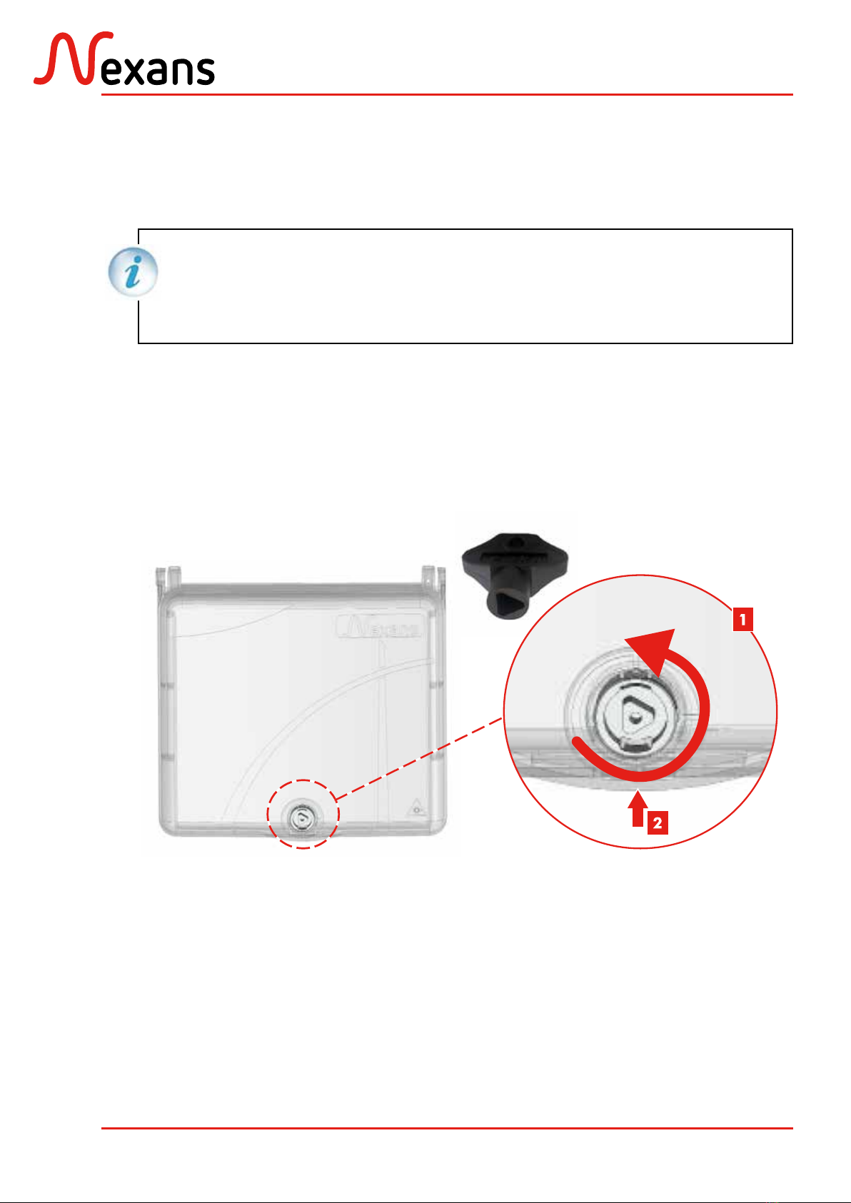
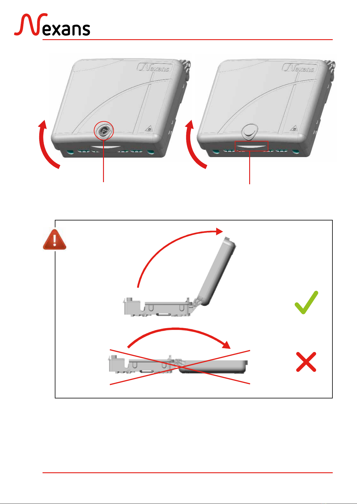
7.1. OUVERTURE FERMETURE DE L’ORGANISEUR CASSETTES
OPENING AND CLOSING THE ORGANIZER............................................................22
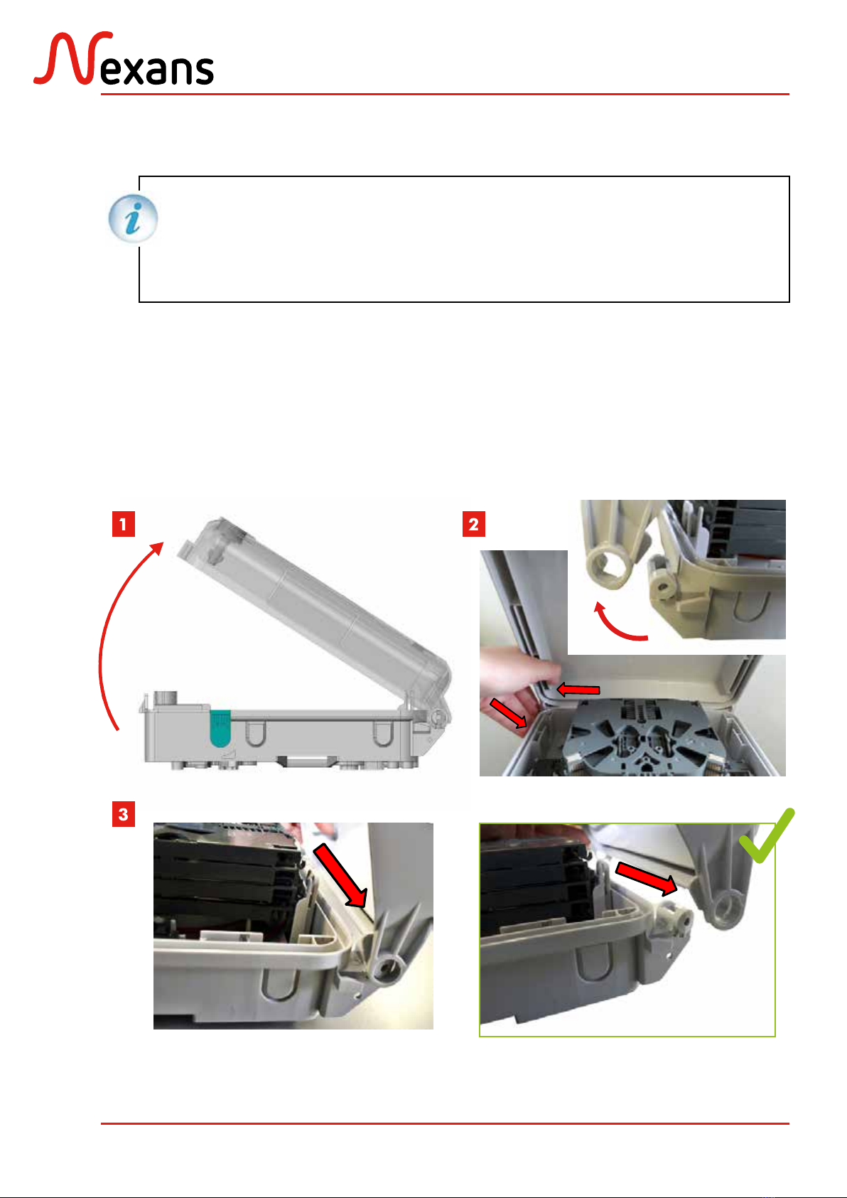
7.2. PRÉPARATION DES CASSETTES POUR LA VERSION 2 X 36 FO STANDARD
PREPARING THE SPLICE TRAYS - 2X36 OF STANDARD VERSION............................... 23
8. PRÉPARATION ET INSTALLATION DU CÂBLE RÉSEAU PRINCIPAL
PREPARING AND INSTALLING THE MAIN NETWORK CABLE .........................24
8.1. PRINCIPE DE RACCORDEMENT DU CÂBLE PRINCIPAL
CONNECTING THE MAIN CABLE - PRINCIPLES........................................................26
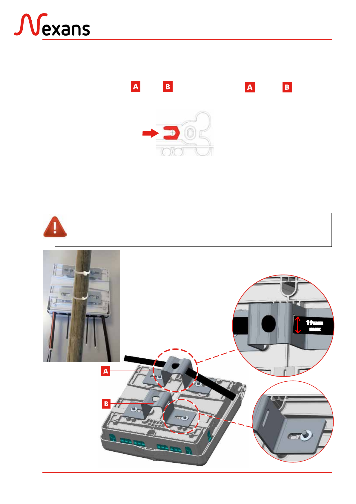
8.1.1. MISE EN PLACE DES PORTEURS DANS L’ÉTRIER
INSTALLING THE STRENGTH MEMBERS IN THE CLAMP ASSEMBLY...............26
8.2. LOVAGE DES MICROMODULES DANS LE BOÎTIER
COILING THE MICROBUNDLES INTO THE DEVICE ..................................................27
8.2.1. VERSION MICROBUNDLE
MICROBUNDLE CONFIGURATION .............................................................27
8.2.2. VERSION LOOSETUBE
LOOSETUBE CONFIGURATION ..................................................................29
9. PRÉPARATION ET RACCORDEMENT DES CÂBLES SECONDAIRES
PREPARING AND INSTALLING THE SECONDARY CABLES ..............................31
9.2. PRÉPARATION DU CÂBLE SECONDAIRE
PREPARATION OF THE SECONDARY CABLE. ...........................................................31
9.3. PRINCIPE DE RACCORDEMENT DU CÂBLE SECONDAIRE
CONNECTION OF THE SECONDARY CABLE ........................................................... 31
9.1. ORDRE DE RACCORDEMENT DES CÂBLES DE DISTRIBUTION
DISTRIBUTION CABLES CONNECTION ORDER........................................................32
9.4. CHEMINEMENT DES CÂBLES DE DISTRIBUTION
ROUTING THE DISTRIBUTION CABLES ..................................................................33
9.4.1. CONFIGURATION CÂBLE MICROBUNDLE
MICROBUNDLE CABLE CONFIGURATION...................................................33
9.4.2. CONFIGURATION CÂBLE LOOSE TUBE
LOOSE TUBE CABLE CONFIGURATION.......................................................34
10. EPISSURAGE
SPLICING .......................................................................................................35
10.1.CHEMINEMENT DU/DES MICRO-MODULE(S) VERS LA/LES CASSETTE(S)
ROUTING THE MICROMODULE(S) TOWARDS THE TRAY(S) ..................................... 36

ABS1476/D 4/44
OUTDROP 2+
10.1.1. DÉRIVATION DES FIBRES EN ATTENTE D’ÉPISSURAGE
SHUNTING OF FIBRES AWAITING SPLICING ...............................................36
11. FERMETURE DU BOÎTIER OUTDROP 2+
CLOSING THE OUTDROP 2+ DEVICE.............................................................41
11.1.FERMETURE DE L’ORGANISEUR
CLOSING THE ORGANISER.....................................................................................41
11.2. RÉINSTALLATION DU CAPOT
REASSEMBLING THE COVER................................................................................... 42
11.3.FERMETURE DU CAPOT
CLOSING THE COVER............................................................................................. 43

ABS1476/D 5/44
OUTDROP 2+
1. DESCRIPTION
OVERVIEW
Le boîtier OutDrop 2+ est spécialement conçu
pour permettre le déploiement, au fil de l’eau,
des câbles de raccordement optique.
Destiné à un usage extérieur et à une
application en façade ou sur poteau, le
boîtier OutDrop 2+ permet un câblage
en piquage épi ou en piquage droit.
Le boîtier OutDrop 2+ permet aussi bien la
gestion des microbundles que des loosetubes.
The OutDrop 2+ device is specially designed
for deploying optical fibre or copper subscriber
cables on demand.
The OutDrop 2+device can be fitted either
on pole mountings or building facades and
offers different cabling possibilities such as
standard configuration, butt or straight mid-
span configuration.
The OutDrop 2+ allows the splicing of
microbundles or loosetubes.
OUTILS NÉCESSAIRES
– Clé triangulaire 8 mm
– Matériel de dénudage standard
– Mètre
– Matériel de découpe des joints
– Tournevis cruciforme
REQUIRED TOOLS
–8 mm triangular key
–Standard stripping tools
–Measuring tape
–Standard seal cutting tools
–Cross-head screwdriver
Désignation Designation Qté / Qty
Boîtier - Case 1
Capot - Cover 1
Serrure triangulaire
(en option, montée sur le boîtier, clé non fournie)
-Triangularkeylock(optional,mounted
on the device, key not supplied) 1
Etiquette (en option, à coller) - Safety sticker (optional) 1
Butées de retenue pour cassettes d’épissurage - Splice tray hinges 1
Plateau organiseur (monté sur le boîtier) - Organizer (mounted on the device) 1
Volets (à monter) - Shutters (not mounted) 4
Joints d’étanchéité latéraux - Lateral seals 2
Joint d’étanchéité long pour câble principal et
câbles de distribution
- Mixed use seal (for main cable and
distribution cables) 1
1.1. Présentation du boîtier
Device overview

ABS1476/D 6/44
OUTDROP 2+

ABS1476/D 7/44
OUTDROP 2+
Fig. Zones de lovage et d’arrimage du dispositif OutDrop 2+
Coiling and clamping zones of the OutDrop 2+ device
Zones de lovage et d’arrimage :
1. 1 zone d’arrimage pour câbles de
distribution.
2. 2 zones d’arrimage pour câble principal
(vertical ou horizontal) .
3. 1 tambour de lovage interne permettant
un lovage en « S ».
4. 1 zone de lovage des modules issus du
câble principal.
5. Zone d’acheminement des modules du
câbleprincipal oudescâblesde distribution
vers les cassettes.
Coiling and clamping zones:
1. 1 clamping zone for distribution cables.
2. 2 clamping zones for the main cable
(vertical or horizontal clamping) .
3. 1 internal coiling drum for “figure 8”
pattern.
4. 1 coiling area for bundles shunted from
the main cable.
5. Routing area for bundles shunted from the
main cable or distribution cables towards
splicing trays.
Le tambour de lovage interne permet
d’effectuer un 1/2 tour (ou lovage en « S »)
afin d’éviter le croisement des câbles.
The internal coiling drum allows a
“figure 8” pattern coiling, to avoid
cable entanglement.
S

ABS1476/D 8/44
OUTDROP 2+
1.2. Cassettes d’épissurage
Splicing trays
Lescassettes d’épissurage livrées avecleboîtier
OutDrop 2+ permettent :
– la mise en place de supports d’épissure
d’une longueur de 45 mm,
– le lovage des surlongueurs de fibre 250
µm.
Les deux cassettes d’épissurage se composent
des éléments suivants :
1- 2 supports d’épissurage,
2- 2 volets de maintien,
3- 4 peignes en plastique,
4- 1 couvercle de protection transparent,
5- 2 zones de lovage.
The splicing trays of the OutDrop 2+ device
allow:
– the installation of splice holders with a
lenght of up to 45 mm.
– the coiling of extra 250 µm fibre lengths.
The two splicing trays are made up of the
following elements:
1- 2 splice holders,
2- 2 shutters,
3- 4 plastic combs,
4- 1 transparent plastic cover,
5- 2 coiling areas.
La capacité maximale du boîtier
OutDrop 2+ est de 72 épissures de
fibres G657.
The OutDrop 2+ device has a maximal
capacity of 72 splices of G657 optical
fibres.

ABS1476/D 9/44
OUTDROP 2+
2. CARACTÉRISTIQUES TECHNIQUES
TECHNICAL CHARACTERISTICS
– Poids (à vide) : 0,700 kg
– Aspect : RAL 7035
– Dimensions (mm) - voir page suivante :
245 x 237 x 78 mm
–Weight (empty): 0,700 kg
–Finish: RAL 7035
–Dimensions (mm) - see next page:
245 x 237 x 78 mm
Matériaux
Extérieur :
Boîtieret couvercle thermo-plastique
Intérieur :
Cassettes en polycarbonate
Materials
External:
Thermoplastic case and cover
Internal:
Polycarbonate splice trays
Capacité 2 doubles cassettes pour
36 épissures fusion. Splice capacity 2 two-sided splice trays for
36 fusion splices.
Entrées de
câbles
4 ports pour câble principal,
Ø 14 mm maxi.
12 ports pour câbles abonnés,
Ø 4 à 8 mm.
Cable ports
4 ports for main cable, Ø 14mm max.
12 cable ports for subscriber cables
Ø 4 to 8mm.
Étanchéité IP55 Tightness IP55

ABS1476/D 10/44
OUTDROP 2+
Fig. Boîtier OutDrop 2+ : dimensions
Dimensions of the OutDrop 2+ device

ABS1476/D 11/44
OUTDROP 2+
3. KITS FOURNIS
KITS PROVIDED
LeboîtierOutDrop 2+estlivréavec les éléments
suivants :
– 1 kit de fixation murale,
– 1 kit de peignes,
– 1 kit de colliers de fixation de câbles.
The OutDrop 2+ device includes the following
elements:
–1 wall mounting kit,
–1 combs kit,
–1 plastic ties kit.
3.1. Kit de fixation murale
Wall mounting kit
Le kit de fixation murale est composé des
éléments suivants :
The wall mounting kit contains the following
elements:
Désignation Designation Qté / Qty
Vis de fixation Ø 6 - Fixation screws Ø 6 4
Chevilles de fixation Ø 8 - Wall anchors Ø 8 4
Rondelles - Washers 4
Etiquette (en option) - Laser safety tag (optional) 1
3.2. Kits de peignes
Comb kits
Fig. Peigne pour micromodule Ø900 µm et outil d’aide à la mise en place
Plastic comb for Ø900 µm microbundle and its tool
Outil d’aide à la mise en place
Tool Peigne plastique
Plastic comb
3.2.1. Kit de peignes spécifiques micromodules (selon configuration)
Microbundle Comb kit (optional)
Le peignedédié aux micromodules et aux tubes
deØ1,3à1,6mmestlepeigne plastiquen°11.
The specific comb used for microbundles and
tubes Ø1.3 mm to 1.6 mm is the plastic comb
n°11.
Le peigne dédié aux micromodules
de Ø1,1 mm est le peigne plastique
25 (Ø900 µm) avec outils d’aide à la mise en
place des micro-modules.
The specific comb used for Ø1,1 mm
microbundles is the plastic comb 25
(Ø900 µm), with tool.

ABS1476/D 12/44
OUTDROP 2+
Le kit de peignes est composé des éléments
suivants :
– 3 peignes en plastique n°1, Ø1,6 mm,
– 3 peignes en plastique n°2, Ø2,4 mm,
– 3 peignes en plastique n°3, Ø2,8 mm.
The comb kit contains the following elements:
– 3 plastic combs n°1, Ø1.6 mm,
– 3 plastic combs n°2, Ø2.4 mm,
– 3 plastic combs n°3, Ø2.8 mm.
Ø 1,6 mm Ø 2,4 mm Ø 2,8 mm
3.2.2. Grappe de peignes spécifiques loose tube (selon configuration)
Loose tube Comb kit (optional)
Le kit de colliers plastique est composé des
éléments suivants :
– 4colliersde fixationenplastiquetranslucide
grand modèle, utilisés pour la fixation du
câble de distribution ;
– 12 colliers de fixation en plastique
translucide petit modèle, utilisés pour la
fixation des câbles abonnés.
The plastic ties kit contains the following
elements:
–4 large translucent plastic ties, used to
tie the main cable;
–12 small translucent plastic ties; used to
tie client cables.
3.3. Kit de colliers de fixation de câbles
Plastic ties kit
3.3.1. Anneau de guidage autoadhésif spécifique loose tube
Self-adhesive guide ring (loose tube configuration only)
L’anneau de guidage autoadhésif doit être
installé à l’intérieur du support de cassettes
métallique, sous la charnière.
The self-adhesive guide ring must be installed
inside the metallic splice tray holder, under
the hinge.
Anneau de guidage autoadhésif
Self-adhesive guide ring Support métallique
Metallic splice tray holder

ABS1476/D 13/44
OUTDROP 2+
4. KITS OPTIONNELS
OPTIONAL KITS
2 kits d’arrimage sont disponibles en option :
– 1 kit de fixation du boîtier, comprenant un
support universel, 2 écrous et 2 rondelles ;
– 1 kit de tés d’arrimage externe.
2 clamping kits are available as an option:
–1mounting kit, containing a universal
support mounting; 2 nuts and 2 washers.
–1 external clamping kit with T-square
clamps.

ABS1476/D 14/44
OUTDROP 2+
5. PRÉPARATION DU BOÎTIER
PREPARING THE DEVICE
5.1. Ouverture du boîtier OutDrop 2+
Opening the OutDrop 2+ device
1. Utiliser une clé triangulaire 8 mm (non
fournie) pour faire pivoter le 1/4 tour
dans le sens anti-horaire et déverrouiller
le boîtier.
2. Faire pivoter le capot à 110° vers le haut.
1. Use a 8 mm triangular key
(not included) to operate an
anticlockwise rotation and unlock the
device.
2. Rotate the cover 110° upwards to open
the device.
Fig. Ouverture du boîtier OutDrop 2+
Opening the OutDrop 2+ device
Pour les boîtiers ne disposant pas de
serrure, passer directement à l’étape
n°2.
If your OutDrop 2+ device is not
equipped with a lock, please proceed
to step 2 directly.

ABS1476/D 15/44
OUTDROP 2+
110°
180°
Serrure
Lock
Poignée
Handle
110°110°

ABS1476/D 16/44
OUTDROP 2+
5.2. Dépose du capot
Disassembling the cover
1. Incliner le capot à 35° environ.
2. Pousser le capot vers la gauche, jusqu’à
ce que son côté gauche se désolidarise
du dispositif.
3. Conserver la même inclinaison et faire
coulisser le capot vers la droite pour le
désolidariser totalement.
1. Perform a 35° rotation on the cover.
2. Push the cover towards the left, until
the left leg comes off the device.
3. Keeping the 35° angle, gently slide the
cover to the right to remove it totally.
Le capot du dispositif est conçu pour
rester ouvert lors des interventions à
l’intérieurdu boîtier. Ladépose du capot
est donc optionnelle.
The cover of the device is designed
to remain open while operators
proceed to splicing operations.
The cover disassembly is optional.
35°

ABS1476/D 17/44
OUTDROP 2+
6. INSTALLATION DU BOÎTIER
MOUNTING
6.1. Cas de l’installation murale
Wall mounting
1. Localiser les 4 opercules de fixation sur
le dispositif.
2. Choisir 2 gabarits de perçage et
désoperculer à l’aide d’un tournevis.
3. Utiliser les chevilles et les vis de fixation
pour procéder à la fixation murale du
dispositif.
1. Identify the 4 cover plates on the device.
2. Choose 2 of them and pierce them using
a screwdriver.
3. Use the wall anchors and the fixation
screws to mount the device on the wall.
Fig. Gabarits de perçage - vue du dessous du boîtier
Mounting holes - bottom view
Gabarits de perçage
Mounting holes
Choisir et utiliser 2 gabarits pour le
perçage et l’installation des chevilles.
Choose and use 2 mounting holes to
fit the anchors.
Si le boîtier est déjà câblé, veiller
à ne pas endommager les fibres.
Please be careful not to break
the fibres if the device is already
equipped with fiber optic.

ABS1476/D 18/44
OUTDROP 2+
Fig. Installation du collier de fixation
Installing the mounting strap
1. Localiser les fentes au dos du boîtier
OutDrop 2+.
2. Insérerun collier de fixation(feuillard inox)
dans les fentes.
1. Identify the slots at the rear of the
OutDrop 2+.
2. Insert the mounting strap (stainless steel
metal strip) in the slots.
6.2. Cas de l’installation directe sur poteau
Direct pole mounting
La largeur du collier (feuillard
inox) ne doit pas dépasser 25 mm.
The width of the mounting strap
(stainless steel metal strip) must
not exceed 25mm.
25mm

ABS1476/D 19/44
OUTDROP 2+
6.3. Cas de l’installation avec un support universel (option)
Universal support mounting (option)
La largeur du collier (feuillard
inox) ne doit pas dépasser 19 mm.
The width of the collar (stainless
steel metal strip) must not exceed
19mm.
1. Sélectionner la position de fixation du/des
support(s) universel(s) ( et/ou ).
2. Insérer les vis dans le logement prévu à
cet effet.
3. Fixer le support universel à l’aide des deux
écrous et rondelles prévus à cet effet.
4. Insérerun collier de fixation dansles fentes
du support universel et fixer l’ensemble
au poteau.
1. Select the position of the universal
support(s) ( and/or ).
2. Insert the screws in the dedicated slot.
3. Fix the universal support using the two
dedicated nuts and washers.
4. Insert a mounting strap into the slots of
the universal support and fix the device
on the pole.
19mm
max

ABS1476/D 20/44
OUTDROP 2+
ABS1476/D 20/44
OUTDROP 2+
6.4. Préparation et mise en place des joints d’étanchéité
Preparing and installing the cable seals
6.4.1. Joint d’étanchéité principal
Main cable seal
Le joint d’étanchéité principal est composé des
zones suivantes :
– 2 passages pour câbles principaux .
– 4x3passagespourcâbles secondaires .
The main cable seal is made up of the following
areas:
–2 main cable entries .
–4x3 secondary cable entries .
Afin de préserver l’étanchéité
du boîtier, veiller à découper
uniquement les entrées néces-
sairesetàbienrepositionnerlejoint
principal après l’opération.
In order to preserve the sealing
control of the device, cut out the
necessary cable entries only. Also
make sure the main cable seal
is properly installed after the
intervention.
Ces passages doivent être découpés
selon le nombre de câbles utilisés
uniquement.
Cable entries must be specifically cut out
according to the number of cables used.
1. Al’aided’untournevisoud’unoutilpointu,
percer les 2 passages en forme de croix.
2. A l’aide d’un cutter, pratiquer une incision
verticale au niveau des 2 passages de
câbles principaux comme indiqué
sur le schéma.
1. Use a screwdriver or a sharp tool to perform
a x-shaped hole and allow cable entries.
2. Perform a vertical incision as depicted
above in using a box cutter.
Other manuals for OutDrop 2+
1
Table of contents
Other Nexans Cables And Connectors manuals

Nexans
Nexans Euromold K200LR User manual

Nexans
Nexans EUROMOLD K800PB/G User manual

Nexans
Nexans 400AR-8 User manual

Nexans
Nexans OUTDROP 2+ SFM Series User manual

Nexans
Nexans N42i.900 User manual

Nexans
Nexans XPLORER Series User manual

Nexans
Nexans ABS1335 User manual

Nexans
Nexans N-HEAT MILLIMAT User manual

Nexans
Nexans Euromold K489TB/G User manual

Nexans
Nexans Euromold K480TB/G User manual