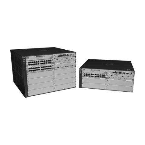
Nexans GigaSwitch V5 TP SFP-2VI 54VDC User manual

88303910 GigaSwitch V5 TP(PSE+) SFP-2VI 54VDC
88303920 GigaSwitch V5 TP SFP-2VI 54VDC
88303990 GigaSwitch V5 2TP(PSE+) SFP-VI 54VDC
88303991 GigaSwitch V5 2TP(PD-F+) SFP-VI 54VDC
88303992 GigaSwitch V5 2TP SFP-VI 54VDC
88303971 GigaSwitch V5 SFP-2VI 230VAC
88303975 GigaSwitch V5 TP SFP-VI 230VAC

Generated 2021-11-17
Page 2/38
Foreword
FOREWORD
Nexans Advanced Networking Solutions offers over 35 years of experience in research, development and production of
Fibre To The Office (FTTO) switches, Industrial Ethernet switches and network design. All key components are
designed and manufactured by Nexans in Germany to offer highest product quality and lifetime.
Nexans “Made in Germany” IT-networking solutions have proven their reliability in countless projects with over 1 million
user ports installed. As a market pioneer for Fibre To The Office Systems, Nexans has a strong R&D heritage based on
the principal of close customer centric product development and supports customers through all stages of even the
most complex projects with a dedicated support department.
Nexans Advanced Networking Solutions GmbH is part of Nexans headquartered in Paris and listed on Euronext Paris,
Compartment A with a main footprint on the European market.
A scalable and flexible IT infrastructure forms the basis for smooth operation and guarantees high-
performance network performance for today's and tomorrow's applications.
Fibre is the best medium because of its scalability. The Fibre to the Office (FTTO) concept combines the benefits of
fibre with the flexibility, cost-effectiveness, and interoperability requirements of today's enterprise networks.
Purpose of this user manual
This manual describes the features, functions, operation and initial operation of the GigaSwitch V5 series. It may
include more than one product. Part of the content, e.g. some use cases or specifications, may only apply to some of
them. For more information on the exact feature set and specifications, see the product’s web page and datasheet.
Target group
Planners and installers of FTTO solutions, electrical engineers, persons entrusted with setting, testing and maintaining
FTTO switches.
Support
If you are not yet a registered user of Nexans Support Portal, please register at the Nexans support portal
https://www.nexans-ans.de/support/ and download the latest version of the firmware and the management tool. In the
Support Portal you will also find the related V5 release notes and the current versions of V5 management manual.
If you have any questions or problems, please contact us at the following support e-mail address:
In order to benefit from individualized and extended product support, we recommend concluding a Nexans support
Disclaimer
The content of this manual has been checked for compliance with the hardware and software described. Nevertheless,
deviations cannot be ruled out, so no liability is assumed for the complete agreement. The information in this manual is
reviewed regularly and any necessary corrections are included in subsequent editions. Suggestions for improvement
are welcomed. Technical changes are reserved, even without notice.
Further information can be found at www.nexans.de/LANsystems
Nexans Advanced Networking Solutions GmbH
Bonnenbroicher Str. 2-14
41238 Moenchengladbach
Germany
Tel: +49 2166 27-2220
E-Mail: [email protected]

Generated 2021-11-17
Page 3/38
Table of Contents
TABLE OF CONTENTS
Foreword...........................................................................................................................................................................1
Table of Contents..............................................................................................................................................................3
EC Declaration of Conformity............................................................................................................................................4
Features and Benefits.......................................................................................................................................................5
Specifications....................................................................................................................................................................6
Dimensions.....................................................................................................................................................................11
Interface Description.......................................................................................................................................................12
Product Labels................................................................................................................................................................16
Safety Instructions...........................................................................................................................................................17
Installation of FTTO switches..........................................................................................................................................18
Horizontal and Vertical Installation..................................................................................................................................19
Power Connection...........................................................................................................................................................21
Grounding.......................................................................................................................................................................23
Hardware Installation ......................................................................................................................................................24
Installation Distances......................................................................................................................................................26
Power over Ethernet .......................................................................................................................................................27
Memory Cards and Console Cable.................................................................................................................................29
LED Behavior..................................................................................................................................................................30
Start-up –Booting...........................................................................................................................................................31
Configuration- and Reset Button.....................................................................................................................................32
LANactive Manager.........................................................................................................................................................34
GigaSwitch Product List..................................................................................................................................................35
Accessories.....................................................................................................................................................................37

Generated 2021-11-17
Page 4/38
EC Declaration of Conformity
EC DECLARATION OF CONFORMITY
The manufacturer
Nexans Advanced Networking Solutions GmbH
Bonnenbroicher Strasse 2-14
41238 Moenchengladbach
Germany
declares under its sole responsibility that the products:
•88303910 GigaSwitch V5 TP(PSE+) SFP-2VI 54VDC
•88303920 GigaSwitch V5 TP SFP-2VI 54VDC
•88303990 GigaSwitch V5 2TP(PSE+) SFP-VI 54VDC
•88303991 GigaSwitch V5 2TP(PD-F+) SFP-VI 54VDC
•88303992 GigaSwitch V5 2TP SFP-VI 54VDC
•88303971 GigaSwitch V5 SFP-2VI 230VAC
•88303975 GigaSwitch V5 TP SFP-VI 230VAC
following the provisions of directives
•2014/30/EU Electromagnetic Compatibility Directive
•2014/35/EU Low Voltage Directive
•2011/65/EU RoHS 2
to which this declaration relates are in conformity with the following directives and standards:
•EN 62368-1:2014: Audio/video, information and communication technology equipment - Part 1: Safety
requirements
•EN 55032:2012: Electromagnetic compatibility of multimedia equipment - Emission requirements
•EN 55024:2016: Information technology equipment - Immunity characteristics - Limits and methods of
measurement
•EN 61000-3-2:2104: Electromagnetic compatibility (EMC) - Part 3-2: Limits - Limits for harmonic current
emissions
•EN 61000-3-3:2013: Electromagnetic compatibility (EMC) - Part 3-3: Limits - Limitation of voltage changes,
voltage fluctuations and flicker in public low-voltage supply systems, for equipment with rated current <= 16A
per phase and not subject to conditional connection
•EN 50581:2012: Technical documentation for the assessment of electrical and electronic products with
respect to the restriction of hazardous substances
The quality and environmental management system of Nexans Advanced Networking Solutions GmbH according to
DIN EN ISO 9001:2000 and DIN EN ISO 14001:2005 ensures compliance with the European Directives and the
fulfilment of the relevant standards of the European standards bodies CEN, CENELEC and ETSI.

Generated 2021-11-17
Page 5/38
Features and Benefits
FEATURES AND BENEFITS
LANactive full managed Gigabit Ethernet FTTO Switches
•Four user ports connecting end devices like PC, VoIP Phones or printer
•Up to three uplinks in various combinations
•Power over Ethernet (PoE+) with up to 30W output power
•Memory Card Slot
•Electrical connection for 54V DC or 230CV AC
Description
Nexans LANactive GigaSwitch V5 series is designed for the installation in Fibre to the Office (FTTO) networks. The
latest generation of FTTO switches is equipped with a state-of-the-art network processor and provides enhanced
performance, security and redundancy functionality.
The LANactive GigaSwitch product portfolio with various port combinations, optionally supporting Power over Ethernet,
can be installed and used in different network infrastructures and fulfil the latest network requirements.
Snap-In Installation
The very compact design of LANactive GigaSwitch allows a tool-less snap-in installation into the standard 45 mm cable
duct systems or floor boxes without special mounting accessories. FTTO installations can be realized in the shortest
possible time in combination with the latest Click-In power supply series.
Power Source Equipment (PSE+)
Depending on the version the LANactive GigaSwitch supports Power over Ethernet (PoE+) functionality. Devices like
VoIP-Phones, Wireless-Access-Points and IP-Cameras can be directly supplied with power from the switch according
to IEEE802.3at. The Power over Ethernet functionality can be parameterized, controlled and monitored via switch
management.
Memory Card
The optional memory card automatically saves the complete current configuration and firmware of the LANactive
GigaSwitch. In case of failure, this feature allows an easy exchange of the hardware without additional configuration. In
addition, each memory card can be delivered with its own MAC address that is adopted by the switch.
Switch Management and Zero-Touch Configuration
The LANactive Manager allows a simple and secure configuration of all device parameter of the GigaSwitch series.
With LANactive Manager a larger number of GigaSwitche systems can be managed and monitored at the same time. In
combination with Nexans Zero-Touch Configuration, the LANactive Manager allows an automatic distribution of
configurations and firmware updates. A pre-configuration of the switches is not necessary.
Fanless design
The fanless design of the GigaSwitch has many advantages: e.g. energy savings, high MTBF values and noiseless
operation allowing an installation in offices and business environments.
Rotatable User Ports
The module with the four user ports, also called head of the switch, is rotatable and can be mounted in a vertical as well
as in a horizontal installations.

Generated 2021-11-17
Page 6/38
Specifications
SPECIFICATIONS
General specifications
Ordering Information
GigaSwitch V5 TP(PSE+) SFP-2VI 54VDC
GigaSwitch V5 TP SFP-2VI 54VDC
Article Number
88303910
88303920
Interfaces
User Ports (RJ45)
4x 1000Base-T
Uplink Ports (SFP)
2x 100/1000Mbps
Uplink Ports (RJ45)
1x 1000Base-T
RJ45 Ports
Auto-Negotiation, MDI/MDI-X Auto-Cross Over and Auto-Polarity
Eco Mode for RJ45 Ports
Yes
Rotatable Head Module
Yes
Power over Ethernet
Number of PoE User Ports
4x PoE-PSE acc. to IEEE802.3at
Number of PoE Uplink Ports
1x PoE-PSE acc. to IEEE802.3at
-
PoE Mode
30W per Port, Mode A, Pin 1-2/3-6
Max. PoE power budget
150W
120W
Diagnostic Functions (Interfaces)
Digital Diagnostics Monitoring
Interface
Yes
Twisted Pair Cable Diagnostic
Yes
General
Dimensions [W x H x D]
90mm x 45mm x 69mm
Installation Depth
35mm
Material
zinc diecasting / stainless steel
Colour
Pure White, like RAL 9010
Ambient Temperature
Operation: 0 ... 45°C, Storage: -20 ... 85°C
Relative Humidity
20 ... 90% (non-condensing)
Weight
290g
MTBF
> 750,000h

Generated 2021-11-17
Page 7/38
Specifications
Power Supply
Input Voltage
46 … 57V DC (typ. 54V DC)
Power Consumption
4.4W typical, 6.2W max.
Heat Output
22Btu(IT)/h
Connector
3-pin connector (up to 2.5mm²) / (+) (-) (FPE)
CE - Conformity
Electro Magnetic Capability
Directive
2014/30/EU
Low Voltage Directive
-
RoHS 2
2011/65/EU
Engineering Standards
EN 62368-1, EN 55032, EN 55024, EN 50581

Generated 2021-11-17
Page 8/38
Specifications
Ordering Information
GigaSwitch V5
2TP(PSE+) SFP-VI 54VDC
GigaSwitch V5 2TP(PD-F+)
SFP-VI 54VDC
GigaSwitch V5 2TP
SFP-VI 54VDC
Article Number
88303990
88303991
88303992
Interfaces
User Ports (RJ45)
4x 1000Base-T
Uplink Ports (SFP)
1x 100/1000Mbps
Uplink Ports (RJ45)
2x 1000Base-T
RJ45 Ports
Auto-Negotiation, MDI/MDI-X Auto-Cross Over and Auto-Polarity
Eco Mode for RJ45 Ports
Yes
Rotatable Head Module
Yes
Power over Ethernet
Number of PoE User Ports
4x PoE-PSE acc. to IEEE 802.3at
Number of PoE Uplink Ports
2x PoE-PSE acc. to
IEEE802.at
1x PoE-PD
1x PoE-PSE
acc. to IEEE802.at
-
PoE Mode
30W per Port, Mode A, Pin 1-2/3-6
Max. PoE power budget with
ext. PS
150W
120W
Max. PoE power budget as PD
-
19.5W
-
Diagnostic Functions (Interfaces)
Digital Diagnostics Monitoring
Interface
Yes
Twisted Pair Cable
Diagnostic
Yes
General
Dimensions [W x H x D]
90mm x 45mm x 69mm
Installation Depth
35mm
Material
zinc diecasting / stainless steel
Colour
Pure White, like RAL 9010
Ambient Temperature
Operation: 0 ... 45°C, Storage: -20 ... 85°C
Relative Humidity
20 - 90% (non-condensing)
Weight
290g
MTBF
> 750,000h

Generated 2021-11-17
Page 9/38
Specifications
Power Supply
Input Voltage
46 … 57V DC (typ. 54V DC)
PoE acc. to IEEE802.3at or
46 … 57V DC (typ. 54V DC)
Power Consumption
5.3W (typ.) ... 6.2W (fully connected)
Heat Output
22 Btu(IT)/h
Connector
3-pin connector (up to 2.5mm²) / (+) (-) (FPE)
CE –Conformity
Electro Magnetic Capability
Directive
2014/30/EU
Low Voltage Directive
-
RoHS 2
2011/65/EU
Engineering Standards
EN 62368-1, EN 55032, EN 55024, EN 50581

Generated 2021-11-17
Page 10/38
Specifications
Ordering Information
GigaSwitch V5 TP SFP-VI 230VAC
GigaSwitch V5 SFP-2VI 230VAC
Article Number
88303975
88303971
Interfaces
User Ports (RJ45)
4x 1000Base-T
Uplink Ports (SFP)
1x 100/1000Mbps
2x 100/1000Mbps
Uplink Ports (RJ45)
1x 1000Base-T
-
RJ45 Ports
Auto-Negotiation, MDI/MDI-X Auto-Cross Over and Auto-Polarity
Eco Mode for RJ45 Ports
Yes
Rotatable Head Module
Yes
I/O Contacts
1x function input for connecting a dry contact
Diagnostic Functions (Interfaces)
Digital Diagnostics
Monitoring Interface
Yes
Twisted Pair Cable
Diagnostic
Yes
General
Dimensions [W x H x D]
90mm x 45mm x 69mm
Installation Depth
35mm
Material
zinc diecasting / stainless steel
Colour
Pure White, like RAL 9010
Ambient Temperature
Operation: 0 ... 45°C, Storage: -20 ... 85°C
Relative Humidity
20 ... 90% (non-condensing)
Weight
290g
MTBF
> 750,000h
Power Supply
Input Voltage
85 … 240V AC (typ. 110V or 230V AC)
Power Consumption
4.5W typical, 5.7W max.
Heat Output
22Btu(IT)/h
Connector
3-pin screwable connector (up to 1.5mm²) / (PE) (L) (N)
CE –Conformity
Electro Magnetic Capability
Directive
2014/30/EU
Low Voltage Directive
2014/35/EU
RoHS 2
2011/65/EU
Engineering Standards
EN 62368-1, EN 55032, EN 55024, EN 61000-3-2, EN 61000-3-3, EN 50581

Generated 2021-11-17
Page 11/38
Dimensions
DIMENSIONS
Figure 1: LANactive GigaSwitch dimensions

Generated 2021-11-17
Page 12/38
Interface Description
INTERFACE DESCRIPTION
88303910
Number
Description
1
Port 1 - 4: RJ45 User Ports (PoE-PSE)
2
Memory card slot (microSD)
3
Grounding terminal
4
Port 7: SFP Uplink
5
3-pin power connection
6
Port 6: RJ45 Uplink (PoE-PSE)
7
Port 5: SFP Uplink
8
Status LEDs
9
Labelling
88303920
Number
Description
1
Port 1 - 4: RJ45 User Ports (PoE-PSE)
2
Memory card slot (microSD)
3
Grounding terminal
4
Port 7: SFP Uplink
5
3-pin power connection
6
Port 6: RJ45 Uplink
7
Port 5: SFP Uplink
8
Status LEDs
9
Labelling

Generated 2021-11-17
Page 13/38
Interface Description
88303990
Number
Description
1
Port 1 - 4: RJ45 User Ports (PoE-PSE)
2
Memory card slot (microSD)
3
Grounding terminal
4
Port 7: SFP Uplink
5
3-pin DC power connection
6
Port 6: RJ45 Uplink (PoE-PSE)
7
Port 5: RJ45 Uplink (PoE-PSE)
8
Status LEDs
9
Labelling
88303991
Number
Description
1
Port 1 - 4: RJ45 User Ports (PoE-PSE)
2
Memory card slot (microSD)
3
Grounding terminal
4
Port 7: SFP Uplink
5
3-pin DC power connection
6
Port 6: RJ45 Uplink (PoE-PSE)
7
Port 5: RJ45 Uplink (PoE-PD)
8
Status LEDs
9
Labelling

Generated 2021-11-17
Page 14/38
Interface Description
88303992
Number
Description
1
Port 1 - 4: RJ45 User Ports (PoE-PSE)
2
Memory card slot (microSD)
3
Grounding terminal
4
Port 7: SFP Uplink
5
3-pin DC power connection
6
Port 6: RJ45 Uplink
7
Port 5: RJ45 Uplink
8
Status LEDs
9
Labelling

Generated 2021-11-17
Page 15/38
Interface Description
88303971
Number
Description
1
Port 1 - 4: RJ45 User Ports
2
Memory card slot (microSD)
3
Grounding terminal
4
Function input
5
3-pin AC power connection
6
Port 6: SFP Uplink
7
Port 5: SFP Uplink
8
Status LEDs
9
Labelling
88303975
Number
Description
1
Port 1 - 4: RJ45 User Ports
2
Memory card slot (microSD)
3
Grounding terminal
4
Function input
5
3-pin AC power connection
6
Port 6: RJ45 Uplink
7
Port 5: SFP Uplink
8
Status LEDs
9
Labelling

Generated 2021-11-17
Page 16/38
Product Labels
PRODUCT LABELS
Nexans LANactive GigaSwitch devices are equipped with product labels for the purposes of quality assurance and
documentation. The product labels contain unique device-specific information that can be used for project
documentation. This information includes MAC address and serial number. The two numbers are unique and refer to
each individual device.
The information about the respective MAC address is located twice on the switch. Once on the bottom side of the
device and a second time below the labelling of the user ports. The sticker below the labelling can also be read when
the GigaSwitch is installed.
Use the barcodes of the product label with the MAC address and serial number information to simply read in the device
lists using commercially available scanners and document them in tabular form. Associate the MAC address with the
information about the installation location and the switch description.
Figure 2: Product label
Figure 3: MAC-address label

Generated 2021-11-17
Page 17/38
Safety Instructions
SAFETY INSTRUCTIONS
Safety and warning instructions
Only qualified personnel may install and commission the device. Country-specific regulations must be observed.
•It is only allowed to use the provided 3-pin power connector.
•The dimensions of the supply lines must be sufficient for the connection scenario.
•After installation, cover the terminal area to prevent inadmissible touching of active parts.
MAINTENANCE AND REPAIR
The switches are maintenance-free devices. Repairs are only permitted by the manufacturer or by persons authorized
by the manufacturer. In case of doubt, please contact the manufacturer.
CLEANING
The GigaSwitch can be cleaned using a cloth which has been dampened with a mild cleaning agent. Please take care
that no cleaning agent enters the interior of the unit.
WASTE MANAGEMENT
After use, the Nexans LANactive GigaSwitch and all electronic parts contained in the scope of delivery
must be disposed of properly according to legal law at a responsible collection point.
ATTENTION: Electrical damage
For device protection, connect a thermomagnetic fuse.
CAUTION: Danger due to electric shock!
Never work with applied voltage.
Packaging
Do not throw away the packaging. The packaging has been designed for repeated use if not damaged during transport.
Only the original packaging can reliably protect the unit from damage during later transport.
Checking for transport damage
Please check the unit for transport damage after unpacking. Transport damage can be assumed in particular if the
packaging is visibly damaged. Do not try to operate an obviously damaged unit. This may result in further consequential
damages.
Recovery after storage and transport
Humidity can condensate on the unit if the unit has been stored or transported at low temperatures and subsequently
taken into a warm room. To avoid any damage please wait till any condensation has vanished from the unit's surface
before starting the uni. The unit is operational only after it has reached the guaranteed operating temperature range
(see Technical Data). The same applies also to prior storage at high temperatures.

Generated 2021-11-17
Page 18/38
Installation of FTTO switches
INSTALLATION OF FTTO SWITCHES
Sophisticated design: The Nexans switches and Click-In power supplies support tool-free installation with a 45mm
installation format. The compact design of the products makes it easy to integrate the devices into new and existing
building installations. The integration of the network components can be adapted and executed according to individual
needs.
Full flexibility: Nexans FTTO switches can be combined with a variety of standard installation materials from various
international manufacturers. All FTTO switches can be easily used with the mounting frames, covers and profiles.
Furthermore, Nexans offers its own universal mounting accessories to simplify the installation, assembly and
disassembly of the devices and to ensure the best possible integration. Nexans also offers special and custom
mounting kits.
Figure 4: Cable duct installation
Figure 5: Floor box installation
Figure 6: In-wall installation
Figure 7: On-wall installation
Figure 8: Desk installation
Figure 9:Communication pilar installation

Generated 2021-11-17
Page 19/38
Horizontal and Vertical Installation
HORIZONTAL AND VERTICAL INSTALLATION
Horizontal and vertical installation with a 45 mm Snap-in design
The GigaSwitches are designed primarily for installation in parapet and cable ducts with horizontal guidance. The low
overall height and the vertical guidance of the connection lines extend the range of use also to underfloor systems, e.g.
floor boxes. The switches feature a rotating switch head with Power over Ethernet function.
The head of the switch with RJ45 connectors can be mounted vertically or horizontally. There is therefore no need to
stock separate system types.

Generated 2021-11-17
Page 20/38
Horizontal and Vertical Installation
12
3 4
5 6
7 8
Other manuals for GigaSwitch V5 TP SFP-2VI 54VDC
1
This manual suits for next models
10
Table of contents
Other Nexans Switch manuals

Nexans
Nexans iGigaSwitch 1604 E + SFP-4VI HW5 Guide

Nexans
Nexans LANmark-OF ENSPACE User manual

Nexans
Nexans iSwitch 740 Manual

Nexans
Nexans LANactive XGigaSwitch DICE User manual

Nexans
Nexans Berk-Tek PowerGIG-OAC User manual

Nexans
Nexans Berk-Tek PowerGIG-OAC User manual

Nexans
Nexans iGigaSwitch 1002 E+ SFP-2VI Guide

Nexans
Nexans GigaSwitch V5 TP SFP-2VI 54VDC User manual

Nexans
Nexans GigaSwitch 641 Desk Guide