Nexans iSwitch 740 Manual

- 1 -
Industrial Ethernet
iSwitch 74x
Description and Operating Instructions KD-0655E06
Fig. 1: iSwitch 742 SFP – front view
Order numbers
7x TP 6x TP / 1x FO 5x TP / 2x FO
iSwitch 740 iSwitch 741 GI(SC)* iSwitch 742 GI(SC)* fiber-optic GI(SC)
iSwitch 740 24V iSwitch 741 24 V GI(SC) iSwitch 742 24V GI(SC)
iSwitch 740 48V iSwitch 741 48 V GI(SC) iSwitch 742 48V GI(SC)
iSwitch 741 GI(ST) iSwitch 742 GI(ST) fiber-optic GI(ST)
iSwitch 741 24 V GI(ST) iSwitch 742 24V GI(ST)
iSwitch 741 48 V GI(ST) iSwitch 742 48V GI(ST)
iSwitch 741 SM(SC) iSwitch 742 SM(SC) fiber-optic SM(SC)
iSwitch 741 24 V SM(SC) iSwitch 742 24V SM(SC)
iSwitch 741 48 V SM(SC) iSwitch 742 48V SM(SC)
iSwitch 741 SM(ST) iSwitch 742 SM(ST) fiber-optic SM(ST)
iSwitch 741 24 V SM(ST) iSwitch 742 24V SM(ST)
iSwitch 741 48 V SM(ST) iSwitch 742 48V SM(ST)
iSwitch 742 SFP modular fiber-optic
iSwitch 742 SFP 24V
iSwitch 742 SFP 48V
* Other single mode (SM) / single fiber (SF) versions e.g. SF5, SF3, L10, L40, L80 on request.

Nexans Active Networking Systems Industrial Ethernet
iSwitch 74x
- 2 -
Overview of the iSwitch 7xx series
iSwitch 74x (740, 741, 742)*
7-port switch with 1 (741) or 2 fiber-optic ports (742)
o3x24VDC (S1, S2,*) supply voltage
o1x48VDC (S4) supply voltage (PoE)
o1x48VDC (S5) – PoE supply via TP port 1 according to IEEE802.3af (Class 2(0))
o2 signalling contacts, 3 signalling or alarm maskings
o10-way DIP configuration switch
ocompact model in robust aluminium edgewise design as desktop, mounting rail and wall enclosure
ounmanaged/managed (option) Power over Ethernet (option)
Options:
oPoE over Ethernet (PoE-PSE) – external supply on port 2, 3, 4, 5 up to a maximum of 15.4W (Class 0)
oiV3-BASIC or iV3-PROFESSIONAL management options for customized configuration
oWeb/Telnet/SNMP user interface
oAdditional V24 (RS232) setup and configuration interface
oMemory card (MMC) for storing configuration files etc.
oSet pushbutton for selecting different boot modes
o..24V version: – 24VDC supply voltage only
o..48V version: – 48VDC supply voltage only
o..12V version: – 12VDC supply voltage (only on request)
* S1..S5 refer to the different supply voltage inputs and indicators
5/6/7x 10/100 TP*
with option: PoE
4xPoE(PSE) up to 15.4W
UNMANAGED
MANAGED
0/1/2x 100 FO*
versions:
SC/ST (GI/SM)
SFP (modular)
M1/M2
signalling contacts
versions:
30VDC / 1A
OPTION: Management
LAN signalling traps
Enhanced functionality
Power supplies:
2x 24VDC (redundant)
1x48VDC
1xPoE (PD) at port 1
Style: screw-on type
Control input:
Disable
(Standby mode)
Configuration:
10-way switch
Style: DIL (on the back)
OPTION:
Management - iV3-BASIC /
iV3-PROFESSIONAL.
OPTION:
Power over Ethernet
4xPoE (PSE) up to 15.4 W
OPTION:
V24 configuration cable
OPTION:
MMC memory card

Nexans Active Networking Systems Industrial Ethernet
iSwitch 74x
- 3 -
Contents
Overview of the iSwitch 7xx series...................2
Contents..............................................................2
Contents..............................................................3
Features...............................................................4
Function and application...................................6
Fiber-optic connection............................................. 6
Device or user ports................................................. 6
Functionality............................................................ 7
Configuration........................................................... 7
Design...................................................................... 7
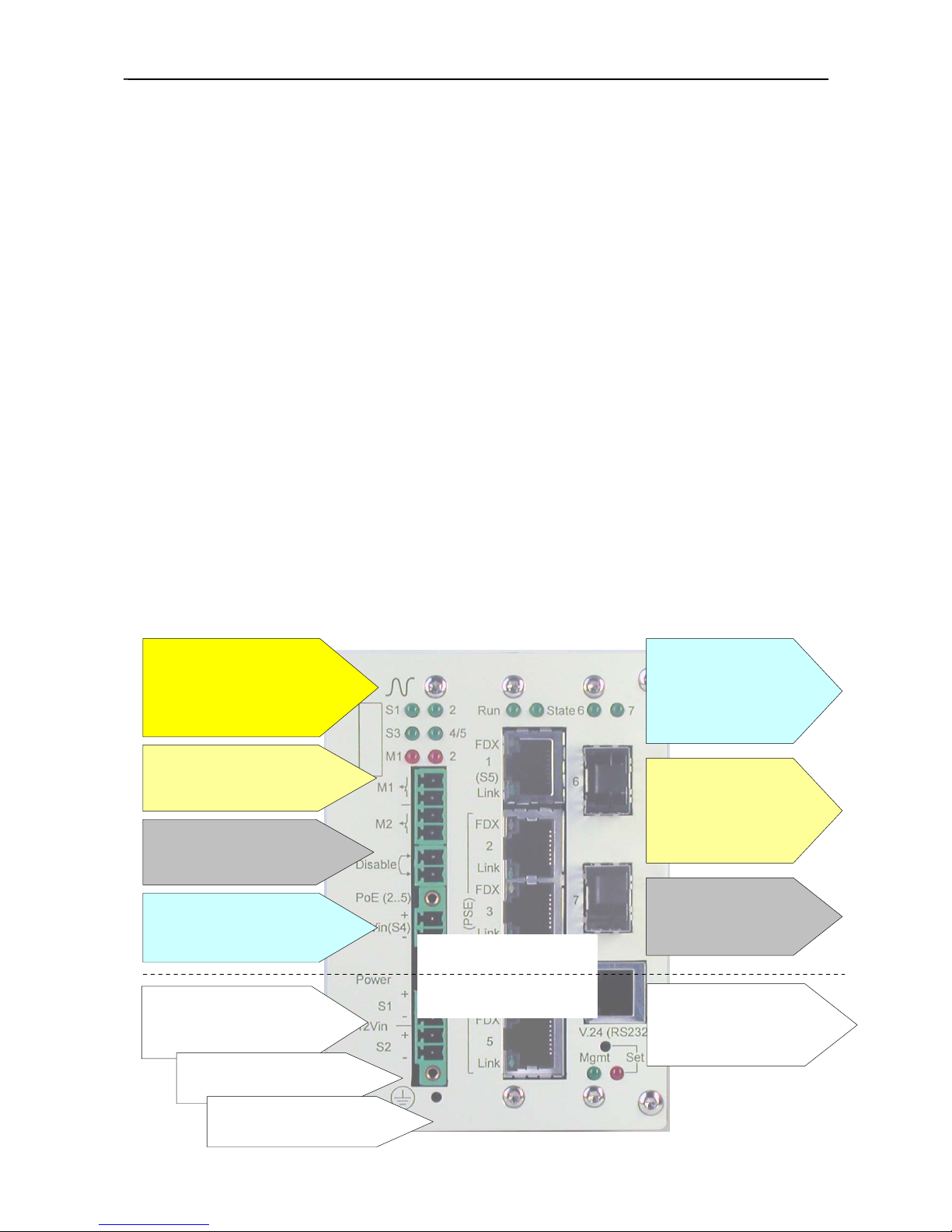
Overview (iSwitch 74x) ......................................8
Safety instructions .............................................9
Proper use ................................................................ 9
Use of laser systems ................................................ 9
Electrical safety ....................................................... 9
Electrical parameters ........................................... 9
Electromagnetic compatibility............................. 9
Environmental conditions........................................ 9
Temperature......................................................... 9
Ventilation ........................................................... 9
Moisture condensation......................................... 9
Instructions on repair and maintenance ............. 10
Opening of the unit............................................ 10
Spare parts ......................................................... 10
Preparation for operation ................................10
Packaging .......................................................... 10
Checking the scope of delivery.......................... 10
Checking for transport damage.......................... 10
Recovery after storage and transport ................. 10
Cleaning the unit................................................ 10
Power supply ..................................................... 10
Mounting – preparation for operation ............11
Unpacking, checking scope of delivery................. 11
Mounting ............................................................... 11
Connection (S1, S2, S4) ........................................ 11
External power supply (S5) – PoE (PD)................ 11
Dismounting (standard version) ............................ 12
Putting into operation ......................................12
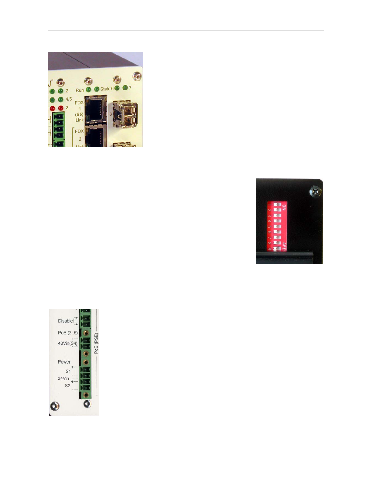
Indicators...........................................................13
Power supply: ........................................................ 13
Signalling /alarm: .................................................. 13
Switch status:......................................................... 13
Port status: 1..5, 6, 7 ............................................. 14
Fiber-optic status: 6, 7 ........................................... 14
Supplementary indicators ...................................... 14
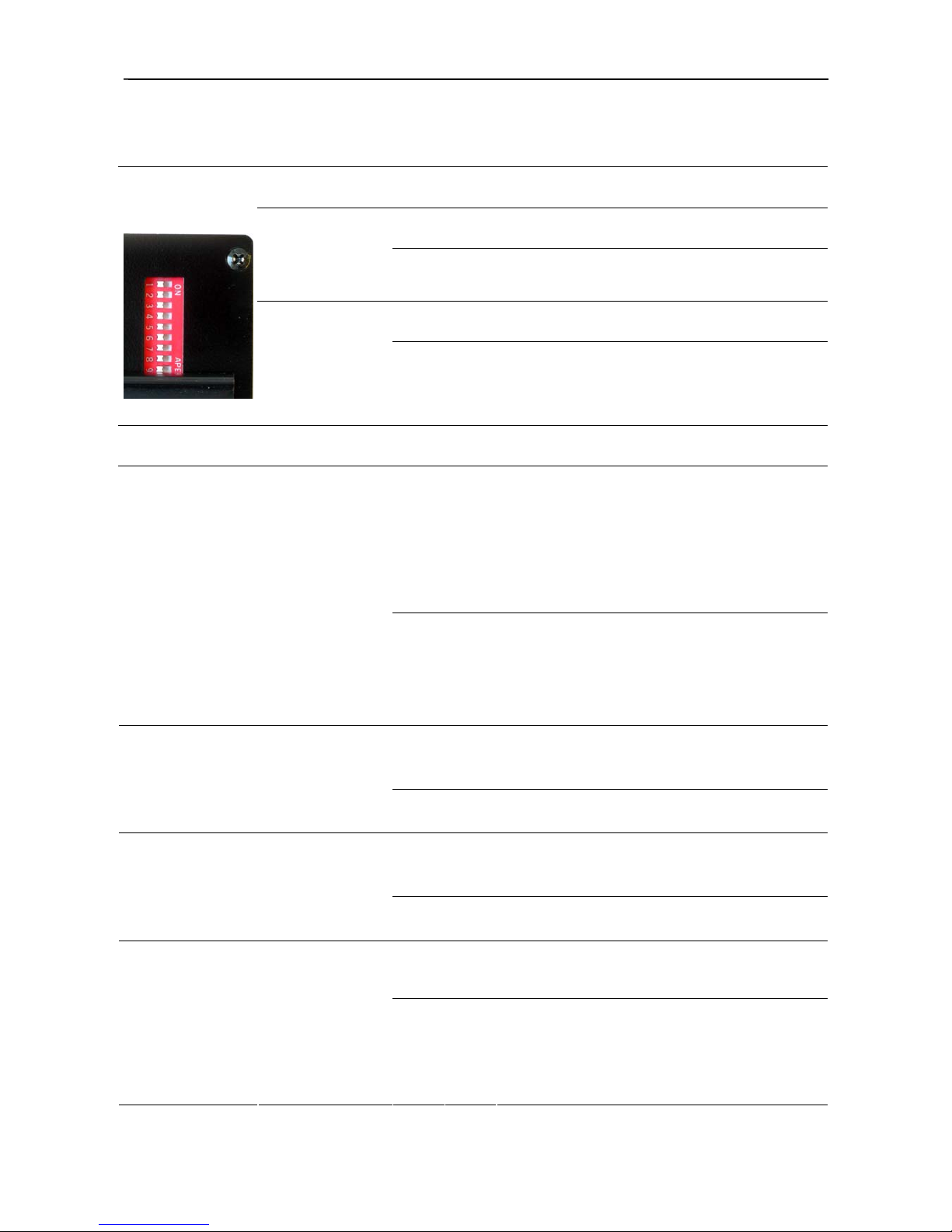
DIP configuration switch (rear panel).............15
Signalling/alarm:................................................ 15
Configuration:.................................................... 15
Signalling contact M1 "Link Loss" ................... 15
Signalling contacts, alarms ............................ 16
Summary of options ........................................ 17
Standard version................................................. 17
24VDC version .................................................. 17
48VDC version .................................................. 17
Option: PoE IEEE802.3af.................................. 17
Option: Management.......................................... 17
Option: MMC memory card for i-system .......... 17
Option: V24 configuration cable........................ 17
Option: PoE IEEE802.3af................................. 18
Power over Ethernet (PoE) .................................... 18
iSwitch with multiple PoE (PSE)*......................... 18
Option: Management....................................... 19
Complementary indicators – Mgmt........................ 19
Hardware reset - Mgmt .......................................... 19
SET configuration pushbutton (front panel) - Mgmt
............................................................................... 21
DIP configuration switch (rear panel) - Mgmt....... 22
Signalling/alarm:................................................ 22
Unused DIP switches ......................................... 22
Option: MMC memory card for i-system ....... 23
Option: V24 configuration cable .................... 23
General configuration notes and
recommendations............................................ 24
Setting the transmission parameters....................... 24
Autonegotiation (NWay) ....................................... 24
MDI/MDI-X Auto-Crossover ................................ 25
Power over Ethernet (PoE) .................................... 25
Technical Data.................................................. 27
General and mechanical specifications .................. 27
Power supply (S1,S2) ............................................ 28
PoE (PSE) power supply (S4)................................ 28
PoE (PD) power supply on TP port 1 (S5) ............ 28
Switch – functional parameters.............................. 29
General features ..................................................... 29
LAN interfaces....................................................... 31
PoE(PSE) Opt. ................................................... 31
Electrical interfaces (TP) ................................... 31
LAN interfaces....................................................... 32
Fiber optic interfaces (FO)................................. 32
SFP interfaces .............. Fehler! Textmarke nicht
definiert.

Nexans Active Networking Systems Industrial Ethernet
iSwitch 74x
Features
General
o7-port switch for connecting devices or users with
LAN interface
oiSwitch 740 – 7 x Twisted Pair (TP) ports
oiSwitch 741 – 6 x TP + 1 x fiber-optic (FO) ports
oiSwitch 742 – 5 x TP + 2 x fiber-optic (FO) ports
o10/100Mbps Ethernet/Fast Ethernet according to
IEEE802.3/-u
o10BASE-T -> 100BASE-FX – for migrating
networks from 10Mbps to 100Mbps
oProtocol-transparent transmission
oStore and forward switch, self-learning
o2 signalling contacts, 2 signalling and/or alarm
maskings
+ unmanaged
o10-way DIP configuration switch
oAutomatic and manual setting of the transmission
mode on all ports
oAutomatic back pressure flow control in half-
duplex (HDX) mode
oFlow control in accordance with IEEE 802.3x in
full-duplex (FDX) mode
oMaskable Link-Loss message on port 1
oMonitored by controller
oReset function
+ managed
(option iV3-BASIC / iV3-PROFESSIONAL)*
oUpdate-ready management system for customized
configuration
oSupports Web/Telnet/SNMP/V24 (RS232) user
interfaces
oComprehensive security management, including
different authentications (RADIUS, IEEE802.1x
etc.)
oAutomatic and manual setting of the transmission
mode on all ports
oComprehensive setup and monitoring features for
Power over Ethernet PoE (PSE)
oAutomatic back pressure flow control can be set in
half-duplex (HDX) mode
oFlow control according to IEEE 802.3x can be set
in full-duplex (FDX) mode
oEnhanced management features such as DHCP,
VLAN, port prioritisation, IEEE802.1p, IPv4,
IPv6, IEEE802.1Q Tagging, QoS, etc.
oSeveral different alarm and signalling traps for
service and security support
oUp to 8 different categorisable trap and/or syslog
receivers
oV24 (RS232) setup and configuration interface
oMemory card (MMC) for storing configuration
files etc.
oSET pushbutton switch for selecting different
boot sequences
* For further information, also on complementary
software tools, please refer to the respective
product descriptions and manuals (see list of
accessories).
Mechanical design
oCompact design
oRobust edgewise aluminium enclosure
oNo-fan system
oLow power consumption
oTop-hat rail mounting
oProtective frame with stands (option)
Indicators
oEasy-to-read LED combinations for displaying the
operating status:
oS1, S2, S4/5 power supply
oM1, M2 signalling/alarm
oRun – switch is ready to operate
oState – status of controller monitoring for port
configuration (unmanaged)
oLink – status: Link and Receive data indication per
port
oFDX - per port = full-duplex transmission
Twisted Pair interfaces
oElectrical interfaces according to IEEE802.3
10BASE-T / IEEE802.3u 100BASE-TX
oMDI/MDI-X auto-crossover and auto-polarity
o10/100Mbps Ethernet/Fast Ethernet Twisted Pair
port – up to 100m
oAutonegotiation / 10/100Mbps Ethernet / Fast
Ethernet / full-duplex or half-duplex
oShielded RJ45 sockets
Fiber Optic interfaces
- 4 -

Nexans Active Networking Systems Industrial Ethernet
iSwitch 74x
oOptical interfaces according to IEEE802.3u
100BASE-FX / 100BASE-SX
oTX and RX wavelengths 1300nm/850nm (SX) or
1550nm/1300nm for SF5 or 1300nm/1550nm for
SF3
oSC/ST/LC/MTRJ fiber-optic connector for graded
index/singlemode fibers or SC SingleFiber (SF)
for singlemode fiber
oSFP plug-in slot for on-site accommodation with
fiber-optic (GI, SM) or Twisted Pair plug-in
modules – also in mixed configurations.
Power supply
oMultiply redundant power supply
oExternal power supply of PoE components via TP
ports 2...5
oIndependent power supply of switch and PoE
components with 24V power supply
oElectrical isolation of the supply voltages from the
system
oProtection against polarity reversal and transients
oNo load sharing
oVoltage indicators for all supply voltages
o5 ways of power supply S1...S5
o24VDC and/or 48VDC supply
24VDC
oS1, S2 – 4-pin terminal block, screw-on type
oLow current consumption
oInput voltage range 18..24..36VDC
48VDC
oS4 – 2-pin terminal block, screw-on type
oS4 – external PoE supply of the PoE-ready devices
connected to TP port 2 to 5
oS5 – external device powering via RJ45 socket of
TP port 1 – PoE (PD)
oPoE (PD) supply of the system via TP data cable
(alternatives A and B)
oInput voltage range 44...48...57VDC
Power over Ethernet (option)
oAccording to IEEE802.3af
oResistive Power Discovery method
oPoE PSE Power Source Equipment (S4)
oExternal powering of attached devices via the TP
data line (endpoint insertion mode B – unused
pairs 4-5, 7-8) on TP ports 2…5
oSupply system power max. 15.4VA/port
depending on parameters of externally connected
48V power supply (S4)
oPower consumption of a connected device max.
12.95VA
oPolarity reversal protection
oPD Powered Device (S5)
oPoE (PD) function = standard, exception:..24V
version
oExternal device powering via TP port 1 (S5) – i.e.
power supply via the TP data line on port 1
oPower consumption according to IEEE802.3af
Class 2 (0)
oMidspan or endpoint insertion - modes A+B, i.e.
via unused pairs 4-5, 7-8 as well alternatively via
data line pairs 1-2, 3-6
oInput voltage range 44V...57VDC
oPolarity reversal protection
Broad range of accessories
oSet of terminal blocks for i-systems
(included in scope of delivery)
oTop-hat rail mounting, plastic
(included in scope of delivery)
oRJ45 dust-protection caps (10 pieces)
oTop-hat rail mounting, aluminium
oMounting rail for i-systems
(for wall mounting)
oEdge protection for i-system type 1
+ managed (options)
oV24 configuration cable
oMMC memory card for i-system
oNEXCON – software tool for easy start-up –
setting of IP addresses, unit status
oNEXMAN – software tool with database for
centralized network service – configuration, update
and monitoring of your network configuration
- 5 -

Nexans Active Networking Systems Industrial Ethernet
iSwitch 74x
Function and application
The Nexans iSwitch 7xx series makes switching technology possible in the local loop. This series emphasizes cost-
effectiveness and flexibility by making up to sixfold use of a central LAN connection – the so-called Uplink.
Twisted-Pair port 1 has been designed by default with enhanced functionality, e.g. alarm masking in case of link loss or
as external input for an external power supply (Power over Ethernet, PoE).
As an option the i-systems can be fitted with Power over Ethernet (PoE) functionality (for power supply) on 4 user ports
(2…5). This enhancement facilitates the external power supply of PoE components according to IEEE802.3af. That means
any connected devices may be supplied with power via the Twisted Pair data connection.
All Nexans iSwitch series systems can be supplied with power via the Ethernet data connection.
Due to PoE (Power over Ethernet) a separate power supply cable is no longer required. The IEEE 802.3af standard
defines that current and voltage supply can also be implemented via the Ethernet LAN cable. 12.95 W are available for
such a power supply. Nevertheless the line length of the Twisted Pair connection is 100m, i.e. it is not restricted by
external powering.
This value is more than sufficient for the
operation of industrial terminals, surveillance
cameras, wireless access points etc. The
Ethernet TP cable need not be modified. It
just has to be a 4-pair cable in line with Cat 5
specifications.
Fiber-optic connection
The iSwitch 741 and 742 have 100BASE-FX
and 100BASE-SX fiber-optic interfaces,
respectively. The transmission mode can be
set from full-duplex (FDX) to half-duplex
(HDX). With half-duplex mode, however, a
length restriction of 412m has to be observed
for the fiber-optic (FO) link in line with the
Fast Ethernet standard. However, in the FDX
mode a fiber-optic distance of 2000m and
more can be bridged.
The optical fibers used can either be graded
index fibers (GI 50/125 μm or 62.5/125μm)
or singlemode fibers (SM 9/125 μm) and
SingleFiber systems (SF5), also on
singlemode basis (SM 9/125 μm), depending
on the requirements. All common optical
connectors are supported (see Technical
Data).
Device or user ports
There are RJ45 ports available on the user
side. The connecting interfaces have been
designed according to IEEE802.3 10BASE-T
and IEEE802.3u 100BASE-TX for up to
100m. Terminal equipment or network segments with a 10/100Mbps Twisted Pair LAN interface can be connected by
means of Cat5 cables (up to 100m in length) here.
The transmission mode is preset to Autonegotiation (see notes on Autonegotiation), and this ensures the transmission
mode (100Mbps FDX/HDX or 10Mbps FDX/HDX) is automatically detected for each of the user ports.
The TP ports also feature a MDI/MDI-X auto-crossover function, which means crossed cables do not need to be used.
The Switch automatically detects if the receive (RD) or transmit (TD) pairs are crossed within the Twisted Pair cabling
and adapts itself accordingly (see "What is MDI/MDI-X auto-crossover").
- 6 -

Nexans Active Networking Systems Industrial Ethernet
iSwitch 74x
Functionality
The self-learning switch works according to the store-and-forward principle.
In full-duplex mode it supports flow control according to IEEE802.3x and
in half-duplex mode it supports the backpressure feature.
ed
ns:
it.
The system has been designed for Power over Ethernet (PoE) features. A
maximum of 4 users can be supplied with power (PoE PSE). Moreover the
system has been designed for external power supply (PoE PD) through a PoE-
ready unit according to IEEE802.3af via Twisted Pair port 1.
In both cases activation, cable wiring, power class for power supply etc. are
automatically negotiated between the devices.
Configuration
A DIP configuration switch on the rear panel further enhances the system's
functionality:
oIndication of power failures
oActivation of signalling contacts
oIndication of link failures
oPort-based selection of the transmission modes, etc.
Note: With built-in Management option parts of the configuration settings are
integrated into the management user interface. That is why the DIP settings are reduc
to the following functio
oIndication of power failures
oActivation of signalling contacts
oF1/F2-specific management settings
Design
The i-series has been designed as a robust industrial enclosure. They can be mounted on top-
hat rails and on walls. When additional edge profiles are used the system can also be employed
as a desktop un
The i-systems can be operated redundantly at 24VDC or 48VDC, also in mixed configurations.
All connections are provided as terminal blocks. Depending on the requirements, some of the
terminal blocks are of the screw-on type.
The possibility of connecting a maximum of 5 independent power supplies increases the
operational security and facilitates an optimum adjustment to the application.
The systems can be externally switched into the energy-saving Standby mode. In this case the
two Disable contacts must be bridged. The Standby mode is signalled via flashing voltage
indicators. This feature is only available with 24V power supply.
- 7 -

Nexans Active Networking Systems Industrial Ethernet
iSwitch 74x
Overview (iSwitch 74x)
(Example: iSwitch 742 SFP)
2x24VDC connection
(redundant)
User ports (10/100Mbps)
4x RJ45 TP sockets PoE (PSE) – for
power supply of a maximum of 4 x
users
Function and status indicators (switch)
TP indicator: amber
programmable
function LED
(see Management)
TP indicator: green
Link and Data
indicator
48VDC connection
external PoE power
supply
Disable – jumper
sets the switch into
Standby mode
Signalling contacts
M1/M2
Power supply status
S1, 2 = 24VDC version
S4, (5) = 48VDC version or PoE Uplink:
1x RJ45 TP socket
user port (10/100Mbps)
Power over Ethernet (PD) – for power
supply via the data connection
10-pin configuration switch (DIL)
Top-hat rail mounting
Rear Panel:
Option: Management
V.24/RS232 interface
Configuration interface
Configuration settings
(booting)
- 8 -

Nexans Active Networking Systems Industrial Ethernet
iSwitch 74x
Safety instructions
When this unit left the factory it was in perfect working order. To operate it without risk, and to ensure it remains in
good working condition, the following safety instructions must be observed.
Proper use
The unit may only be used under conditions and for purposes for which it has been designed. Please find further details
in the sections Introduction and Technical Data.
Any other operation beyond the stipulated conditions may be dangerous for the user or could damage the unit.
WARNING!
•Please observe the permitted environmental conditions!
•Please observe the specified electrical parameters!
•Do not connect any measuring circuits for which the unit has not been designed!
•Unused active fiber-optic ports have always to be covered with the provided caps!
Use of laser systems
(only in units of the types SM(ST), SM(SC), SF5(SC) or SF5+3(SC) for singlemode fibers)
DANGER! Invisible laser radiation!
Radiation can lead to irreparable damage if there is contact with the retina.
WARNING! When the system is switched on, do not look directly into the optical output or a connected
optical fiber. The unit is designed for LAN applications in the invisible 1550nm, 1300nm or 850nm wavelength ranges.
With this application range the output power levels may be dangerous for the user because they are not classified under
the uncritical Laser Class 1.
Electrical safety
If operated for the specified applications the unit meets the protection requirements of the Association of German
Electrotechnical Engineers (VDE).
Electrical parameters
The electrical parameters are specified in the respective Technical Data. The power consumption value on the primary
side is indicated on the type label and/or in the Technical Data.
Electromagnetic compatibility
The installed unit fulfils the requirements of the European standards EN 55022 class A (FCC Part 15, CISPR).
Environmental conditions
Temperature
The unit has been designed for operation at specified ambient temperatures (see Technical Data).
Ventilation
Please note that the ventilation hole must not be covered after mounting.
Between the main units, following ventilation-distances are recommended for the entire operating temperature:
Convection, mounting distance:
10 mm (0,4 inches) left/right
25 mm (1,0 inches) above/below
No special ventilation gaps are necessary between the system units. Please ensure, however, that the ambient
temperature does not exceed the indicated range. Please ensure sufficient ventilation in the data cabinet or at the site of
installation during operation of the unit.
Moisture condensation
The unit must not be operated if there is any moisture condensation. If moisture condensation can not be avoided, such
as when the unit is cold and is taken into a warm room, it must dry out first before being switched on.
- 9 -

Nexans Active Networking Systems Industrial Ethernet
iSwitch 74x
Instructions on repair and maintenance
Any repairs must be executed workmanlike. The design features of the unit must not be altered in a way that impairs
the safety of the unit. This in particular applies to leakage paths and clearances.
Opening of the unit
Please disconnect the unit from the mains supply and from all other power sources prior to opening the unit. Any
subsequent servicing and repair on the open and live unit may only be performed by a qualified person.
Spare parts
Only original spare parts may be used. Any other spare parts are only allowed if they do not impair the safety of the
power supply unit.
Preparation for operation
Packaging
Do not throw away the packaging. The packaging has been designed for repeated use if not damaged during transport.
Only the original packaging can reliably protect the unit from damage during later transport.
Checking the scope of delivery
oUnit including clips for vertical top-hat rail mounting
oTerminal blocks, 4x
oDocumentation
Checking for transport damage
Please check the unit for transport damage after unpacking. Transport damage can be assumed in particular if the
packaging is visibly damaged. Do not try to operate an obviously damaged unit. This may result in further
consequential damages.
Recovery after storage and transport
Moisture can condensate on the unit if the unit has been stored or transported at low temperatures and subsequently
taken into a warm room. In order to avoid any damage please wait till any moisture condensation has vanished from the
unit's surface before switching the unit on. The unit is operational only after it has reached the guaranteed operating
temperature range (see Technical Data).
The same applies also to prior storage at high temperatures.
Cleaning the unit
If the unit has become dirty during use it can be cleaned using a cloth which has been dampened with a mild cleaning
agent. Please take care that no cleaning agent enters the interior of the unit.
Power supply
The unit is equipped with an internal voltage conditioning circuit. For putting into operation the unit is connected to
one of the Power inputs (S1...S5) (24VDC or 48VDC) and will thus become operational.
- 10 -

Nexans Active Networking Systems Industrial Ethernet
iSwitch 74x
Mounting – preparation for operation
Unpacking, checking scope of delivery
1. Please check whether the shipment has been completely delivered (see Scope of Delivery).
2. Check the individual parts for transport damage.
WARNING! Do not operate damaged parts!
Mounting
oPlace the system from above with the slot onto the mounting rail
(35 mm top-hat rail according to DIN EN 50022).
oMetal mounting rail:
oThe racketeer lock downward contrary to the feather-strength, until the system lies flat completely on
the mounting rail. The racketeer let go - the system is arrested.
oHold the front panel and press the system towards the mounting surface until it snaps into place.
oPlastic- and Alu mounting rail:
oHold the front panel and press the system towards the mounting surface until it snaps into place.
oInstall and terminate the signal lines.
Notes:
The front panel of the enclosure is grounded via a ground connection.
The enclosure must not be opened.
The shield ground of the Twisted Pair cables is electrically connected with the front panel.
Connection (S1, S2, S4)
The system is operational when one of the supply voltages S1, S2, S4 or S5 (–> via the Twisted Pair terminal at port 1)
is correctly connected. The supply voltage can be redundantly connected. Alle inputs are isolated. There is no load
sharing available. In case of redundant power supply via S1, S2 only the power supply unit with the higher output
voltage will provide the power. If additionally power is redundantly supplied via S4, only the S1, S2 power supply with
the highest output voltage will deliver power. The supply voltages are isolated from the enclosure.
WARNING!
The iSwitch 74x series has been exclusively designed for operation at separated extra-low
voltages (SELV) according to lEC 950 / EN 60950 / VDE 0805. Thus only PELV voltage
circuits or optionally SELV voltage circuits observing the voltage restrictions according to
IEC/EN 60950 may be attached to the supply voltage connections.
Mount the iSwitch 74x onto a standard mounting rail. Grounding is not provided via snapping into place on a grounded
mounting rail. The unit is to be grounded via the terminal screw on the front panel (grounding icon). In order to
increase immunity in an environment with particularly high EMC interference, a low-impedance connection towards
functional earth should be established.
External power supply (S5) – PoE (PD)
By default (exception: 24V version) the Nexans i-series has been designed in such a way that the i-systems can be
powered as a standard-compliant powered device (PD) via the appropriate Twisted Pair port 1. IEEE802.3af – PD
modes A and B are supported.
Note: If an i-system is powered via PoE (PD), no further terminals can be powered via the PoE (PSE) option
(cascading) due to the power restriction stipulated by the standard.
- 11 -

Nexans Active Networking Systems Industrial Ethernet
iSwitch 74x
Dismounting (standard version)
The system is dismounted in reverse order compared with the mounting procedure.
oMetal mounting rail:
oTo the release racketeers contrary to the feather-strength downward pulls / levers.
oLift the system-front.
oPost from the upper groove of the mounting rail afterwards.
oPlastic- and Alu mounting rail:
oTilt the system upwards by lifting the system front, till the system snaps out of the bottom slot of the
mounting rail.
Putting into operation
Please note:
Please observe the following instructions when putting the unit into operation:
1. Terminal equipment or network components, which are connected to the unit, should be set to the same parameters
(see Notes on configuration). To achieve an optimum performance the following transmission mode and speed
should be set:
Transmission mode to be set
oAll connected Twisted Pair terminals: Autonegotiation
oSystem setting on unit/Switch
all Twisted Pair ports Autonegotiation
without Management option:
DIP configuration switch default = OFF
oTwisted Pair – remote unit (Uplink) Autonegotiation
2. Supply the system with an input voltage of S1...S2 = 24VDC and/or S4/S5 = 48VDC. Operational status is
indicated on the front panel (indication: S1…5).
3. The supply voltages are redundant among one another.
4. A flashing indication of S1...S4 signals the Standby mode, which is triggered using a jumper over the Disable
contacts.
5. Note: Any units which are fitted with the Power over Ethernet option (PoE) should be checked for correct wiring
prior to initial putting into operation.
6. Attach the Twisted Pair connections to the user equipment.
Note: Twisted Pair cabling components (line, patch cords, connectors) with increased attenuation values reduce the
length of the maximum connection or transmission lines.
7. If terminals or network components are switched on, an incoming valid link signal is indicated as Link on the system.
8. Data traffic is indicated using flashing lights.
Note on functions without Management option:
1. The FDX indicator on an unused port indicates a fixed 100 FDX transmission mode (see DIP configuration
switch). If the port is used and if AN (=Autonegotiation) was selected as transmission mode, the current
transmission mode is indicated.
2. Link monitoring can be set via DIP switch 10 on port 1. In case of link loss, signalling contact 1 as well as the
respective M1 indicator are enabled.
- 12 -

Nexans Active Networking Systems Industrial Ethernet
iSwitch 74x
Indicators
Power supply:
Designation
Colour
Description
S1 / S2
green
24VDC supply voltage S1in or S2in
(standard and
24V version)
a) Lights up, if S1/2 = 24V.
b) Is flashing (fast, 4 Hz), if S1/2 = 24V and if the system was
set to Standby via Disable (jumper).
S3
green
not connected
S4/5
green
48VDC supply voltage S4in (48V version)
(standard and
48V version)
a) Lights up, if S1 = 48V connected.
b) Is flashing (fast, 4 Hz), if S1 = 24V and if the system was
set to Standby via Disable (jumper).
(only if S1...S2 are used, i.e. the system is powered with 24V)
c) Is flashing (slowly, 0.5 Hz), if the system is powered via S5,
i.e. TP port 1 PoE (PD).
Signalling /alarm:
Designation
Colour
Description
M1
red
Lights up, if:
a) DIP 1 = ON -> S4 (48V) failure or
b) DIP 10 = ON -> TP port 1 link loss or
c) DIP 10 = ON -> TP port 1 in AN and
partner set to HDX/FDX (link mismatch)
M2
red
Lights up, if:
DIP 2 = ON -> unit in Standby mode,
internal operating voltage disabled
(jumper across Disable contacts)
Switch status:
iSwitch 740, 741, 742
Designation
Colour
Description
Run
green
Lights up, if internal operating voltage is present.
State
green
Port configuration monitoring OK
– Only, if no Management option is available.
- 13 -

Nexans Active Networking Systems Industrial Ethernet
iSwitch 74x
Port status:
1..5, 6, 7
Designation
Colour
Description
Link
green
a) Lights up permanently when the link signal is received at the
TP interface
b) Flashes periodically when data packets are received or sent
at the TP port
FDX
amber
Transmission mode
a) Does not light up, if the "half-duplex" transmission mode is
set on the TP interface or was detected via autonegotiation.
b) Is flashing sporadically, when collisions are detected in half-
duplex (HDX) transmission mode.
c) Lights up, if the full-duplex (FDX) transmission mode is set
on the TP interface or was detected via autonegotiation.
Fiber-optic status:
6, 7
Designation
Colour
Description
6
(only iSwitch
742)
green
FO link
a) Lights up permanently, when a valid link signal is received at
the FO interface.
b) Flashes periodically when data packets are received or sent
at the FO interface.
7
(only iSwitch
741
and iSwitch
742)
green
FO link
a) Lights up permanently, when a valid link signal is received at
the FO interface.
b) Flashes periodically when data packets are received or sent
at the FO interface.
Supplementary indicators
(Only for systems without Management option.)
Management status:
Designation
Colour
Description
Mgmt
green
No function
Set
red
No function
- 14 -

Nexans Active Networking Systems Industrial Ethernet
iSwitch 74x
DIP configuration switch (rear panel)
(Only for systems without Management option.)
Signalling/alarm:
Designation
Description
OFF
-
DIP 1
ON
M1 is enabled:
S4 (48V) failure or not used.
OFF
-
DIP 2
ON
M2 is enabled:
Unit in Standby mode, internal operating voltage
disabled
(jumper across Disable contacts)
Configuration:
Designation
Description
OFF
Transmission mode
AN* (10 HDX / 100 HDX)
* AN = Autonegotiation = automatic selection of the
transmission mode, if both partners support AN. This
setting should also be used when connecting 10 or 100
HDX terminals!
Port 1..7 TP-
iSwitch 740
Port 1...6 TP-
iSwitch 741
Port 1...5 TP-
iSwitch 742
DIP 3 = port 1
DIP 4 = port 2
DIP 5 = port 3
DIP 6 = port 4
DIP 7 = port 5
DIP 8 = port 6
DIP 9 = port 7
ON
Transmission mode
100 FDX
- Setting is also indicated on the unused port (FDX
LED)
Port 7 FO
- iSwitch 741
OFF
Transmission mode
100 HDX
DIP 3...8 see above
DIP 9 = port 7
ON
Transmission mode
100 FDX
Port 6...7 FO
- iSwitch 742
OFF
Transmission mode
100 HDX
DIP 3...7 see above
DIP 8 = port 6
DIP 9 = port 7
ON
Transmission mode
100 FDX
Signalling contact
M1 "Link Loss"
OFF
-
DIP 10
ON
M1 is enabled, if:
a) there is a link loss on port 1 or the port is unused
or
b) port 1 is in AN mode and the partner unit is set to
HDX or FDX (link mismatch).
- 15 -

Nexans Active Networking Systems Industrial Ethernet
iSwitch 74x
Signalling contacts, alarms
Signalling/alarm
:
M2 LED DIP switch Description
M2
OFF
Overall power failure
M2
ON DIP 2 = ON Unit in Standby mode (Disable),
internal operating voltage disabled
(Standby ->jumper across Disable contacts)
Signalling/alarm
:
M1 LED
DIP switch
Description
M1
OFF
Overall power failure
M1
ON
DIP 1 = ON
S4 (48V) failure or not used.
ON
DIP 10 = ON
(unmanaged)
Link loss on TP port 1
or
TP port 1 in AN mode and partner unit set to FDX (link
mismatch).
Note: Function supported "unmanaged" only.
Disable – jumper sets the
switch into Standby mode
Signalling contacts
M1/M2
Supply voltages status
S1, 2 = 24VDC version
S4, (5) = 48VDC version or PoE
Signalling or Alarm indicators
M1/M2
- 16 -

Nexans Active Networking Systems Industrial Ethernet
iSwitch 74x
- 17 -
Summary of options
Standard version
1. 24VDC power supply, redundant S1, S2
2. 48VDC power supply, S4
3. PoE (PD) power supply via TP port 1 (S5)
Universal flexible systems for use in industrial environments with multiply redundant power supplies including
external power supply via PoE.
24VDC version
1. 24VDC power supply, redundant S1, S2
Cost-effective alternative for use in industrial environments with 24VDC power supply. Without any ambition of a
Power over Ethernet power supply.
48VDC version
1. 48VDC power supply, S4
2. PoE (PD) power supply via TP port 1 (S5)
Optimum use of Power over Ethernet technology in industrial environments, including external powering of the
system.
Option: PoE IEEE802.3af
4 times Power over Ethernet as Power Source Equipment (PSE) according to IEEE802.3af for external power supply of
a maximum of 4 terminals via the TP data line from port 2 to port 5.
Option: Management
iV3-BASIC Management system for customized configuration of the switch series via the Web / Telnet / SNMP user
interfaces as well as V24 (RS232) option. iV3-PROFESSIONAL including functions of security and different
authentications (RADIUS, IEEE802.1x etc.).
Option: MMC memory card for i-system
(Can only be used in connection with a management option.)
Option: V24 configuration cable
Cable for connecting the V.24 console (D-Sub, 9-pin) with iSwitch (RJ11, 6-pin).
(Can only be used in connection with a management option.)

Nexans Active Networking Systems Industrial Ethernet
iSwitch 74x
Option: PoE IEEE802.3af
(Only for systems with integrated PoE IEEE802.3af option.)
Power over Ethernet (PoE)
The reduction in the number of cables required for connecting the network equipment is an important precondition in
order to integrate the units more comprehensively into the daily routine of industrial environments. The latest
development in the field of cabling pursues the aim of ensuring the power supply of the attached device via the
Ethernet cable.
The Nexans i-Series for industrial applications uses the so-called PoE (Power over Ethernet) feature. Thus no hybrid
cables, where power is supplied vie separate lines, are used.
Power over Ethernet is an attractive and standardized alternative for the power supply of LAN equipment such as
switches and converters while the „normal“ Ethernet standard cable. Further fields of application of this technology
particularly in the industrial environment would be controlling and reading sensors, the camera surveillance of
processes and plants or signalling and alarm handling.
iSwitch with multiple PoE (PSE)*
An active source (PSE) ensures the power supply of a so-called passive IEEE802.3af-compliant powered device (PD).
The active power source is an iSystem with PoE (PSE) option. A maximum of 4 Twisted Pair ports support PoE with
the following pairing scheme according to IEEE802.3af:
oEndpoint PSE mode B – power supply via the unused TP pairs 4/5 and 7/8
The powered devices can be connected to the ports 2 to 5 using common straight TP patch cords (1:1). The PoE option
will only supply power if an appropriate powered device (PD) is detected.
The following functions are checked prior to enabling power supply:
oExternal supply voltage of 48VDC must be present on terminal block S4.
oThe active system with PoE (PSE) option detects the passively connected powered device (PD).
oThe operational mode is detected.
oThe required power class is detected.
oThe supply voltage is fully enabled, if a standard-compliant terminal unit including Discovery feature
(standard) has been connected.
After removing the terminal unit the PoE supply voltage on the port is disabled for safety reasons.
Thus any damages resulting from short circuits etc. are avoided, if the connected terminal unit is not standard-
compliant.
Note: Some vendors claim that their terminal equipment provides PoE according to IEEE802.3af, although this
equipment only supports the pin assignment of the standard. Please check in any case the correct pin assignment and
the correct polarity of the PoE wiring on the terminal unit (see Technical Data).
This also applies to terminal units which do not comply with IEEE802.3af functionality and are to be powered via PoE.
A non-POE-ready terminal unit can be connected to a port with standard-compliant PoE power supply according to
IEEE802.3af without any risk of damage.
Warning!
Please check compatibility, proper pin assignment and polarity prior to and during putting the system
into operation in order to avoid any damage resulting from the connection of incompatible
equipment. The maximum load of the individual ports and the overall load are limited. These limits
have to be observed in any case. Otherwise the connected units might be damaged or cannot be
operat
ed (see Technical Data).
*PSE = Power Source Equipment
PD = Powered Device
- 18 -

Nexans Active Networking Systems Industrial Ethernet
iSwitch 74x
Option: Management
Currently the following options are available:
oiV3-BASIC
oiV3-PROFESSIONAL
Note: For up-to-date and more detailed information also on complementary software tools please refer to the following
management descriptions and manuals:
oManual – V3 Switch Management Module – describes the integrated management firmware and switch
settings as well as their use on the Web, SNMP, Telnet etc. interfaces.
oManual - Nexans Local Configurator V3 (NexConV3) – describes an easy-to-use Windows application
which facilitates the local configuration of the IP parameters and switch names.
oManual - Nexans Switch Manager V3 (NexManV3) – describes an easy-to-use Windows application which
facilitates the local configuration of the IP parameters and switches.
Complementary indicators – Mgmt
(Only for systems with integrated Management option.)
Note: This function is only available in connection with the Management option. For up-to-date and more detailed
information on the settings and on troubleshooting please refer to the appropriate management descriptions and
manuals.
Management status:
Designation
Colour
Description
Mgmt
green
a) Lights up permanently: Management is operational.
b) Is flashing periodically during reconfiguration and reboot
procedure.
Set
red
a) Lights up as long as the management is in Set mode for
configuration. This mode is automatically disabled after 20
seconds.
b) Flashes once when accepting the Set setting.
Function: Mgmt - Management Status LED
After the system is switched on, a selftest is carried out checking the hardware of the switch and of the management. The
Mgmt LED is not turned on permanently until all tests have been passed successfully without any errors.
If the Mgmt LED flashes repeatedly or remains completely off there must be an error and the management processor has
been stopped. In this case the management module or the switch will have to be replaced.
Hardware reset - Mgmt
(Only for systems with integrated Management option.)
The Set configuration pushbutton of the iSwitch 7xx series is installed on the front panel (down on the right). It can be
accessed above the Set indicator via a whole in the front panel. A pointed object, e.g. a ballpoint cartridge, is needed for
resetting.
oPress and hold the Set pushbutton >30 sec -> trigger Hardware reset
- 19 -

Nexans Active Networking Systems Industrial Ethernet
iSwitch 74x
•A hardware reset is equivalent to a short interruption of
power supply.
- 20 -
This manual suits for next models
8
Table of contents
Other Nexans Switch manuals

Nexans
Nexans LANactive XGigaSwitch DICE User manual

Nexans
Nexans GigaSwitch V5 TP SFP-2VI 54VDC User manual

Nexans
Nexans Berk-Tek PowerGIG-OAC User manual

Nexans
Nexans GigaSwitch 641 Desk Guide

Nexans
Nexans LANmark-OF ENSPACE User manual

Nexans
Nexans GigaSwitch V5 TP SFP-2VI 54VDC User manual

Nexans
Nexans iGigaSwitch 1002 E+ SFP-2VI Guide

Nexans
Nexans Berk-Tek PowerGIG-OAC User manual

Nexans
Nexans iGigaSwitch 1604 E + SFP-4VI HW5 Guide