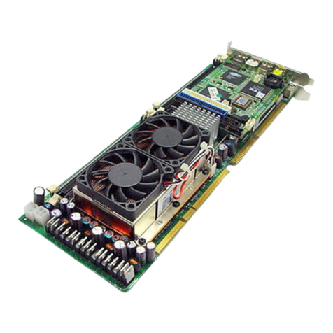
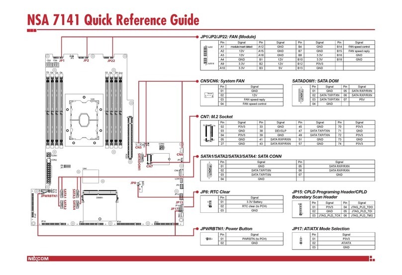
Nexcom Peak 555A User manual

Peak 555A
Single Board Computer
User
′
s Guide
All brand names are registered trademarks of their owners.

@Copyright 1999
All Rights Reserved
Manual edition 1, April 1999
The information in this document is subject to change without prior notice in
order to improve reliability, design and function and does not represent
commitment on the part of the manufacturer.
In no event will the manufacturer be liable for direct, indirect, special,
incidental, or consequential damages arising out of the use or the possibility of
such damages.
This document contains proprietary information protected by copyright. All
rights are reserved. No part of this manual may be reproduced by any
mechanical, electronic, or other means in any form without prior written
permission of the manufacturer.
Trademarks
Peak 555A is registered trademarks of Nexcom International Co., Ltd., IBM
PC is a registered trademark of International Business Machines Corporation.
Intel and Pentium are registered trademarks of Intel Corporation. Award is
registered trademarks of Award Software, Inc. Other product names
mentioned herein are used for identification purposes only and may be
trademarks and/or registered trademarks of their respective companies.

Table of Contents
How to Use This Guide
Chapter 1. Introduction
1.1
Specifications.............................................................................…
1-3
1.2 What you have ………………………………………………….. 1-6
Chapter 2. Switches and Connectors
2.1
Switches.......................................................................................
.2-1
2.2
Connectors...................................................................................
.2-5
Chapter 3. Capability Expanding
3.1 System
Memory........................................................................… 3-1
3.2 Cache
Memory .........................................................................… 3-3
3.3 Change CPU……….…………………………………………….3-3
Chapter 4. Award BIOS Setup
4.1 Entering
Setup...............................................................................4-1
4.2 The Main
Menu ............................................................................. 4-4
4.3 Standard CMOS
Setup ..............................................…................. 4-7
4.4 BIOS Features
Setup. ...............................................................…4-11
4.5 Chipset Features
Setup..................................................................4-16
4.6 Power Management
Setup.............................................................4-21
4.7 PCI & On board I/O
setup.............................................................4-26
4.8 System Environment …………………………………………… 4-
28
4.9 Integrated Peripherals……………………………………………4-
29
4.10 Supervisor/User Password Setting ……………………………. 4-32
4.11 IDE Auto

Detection .................................................................... 4-33
4.12 Power On
Boot......................................................................….4-37
4.13 BIOS Reference-
POST
Message............................................…4-
38
4.14 BIOS Reference-POST Code ……………….........................…4-43
4.15 BIOS Default Drive Table ……………………………………. 4-49
Appendix 1 Watch Dog Timer
Appendix 2 Memory Mapping

How to use this guide
This manual is written to help you use Peak 555A. The manual describes how
to arrange various settings on the Pentium CPU board to meet your
requirements. It‘s briefed as follows:
Chapter 1, “Introduction” gives an overview of the product‘s specifications.
It also tells you what are included in the product package.
Chapter 2, “Jumpers and Connectors” describes the definitions and positions
of Jumpers and Connectors that you may easily configure and set up per your
requirement.
Chapter 3, “Capability Expanding” describes how to change or expand the
CPU Board by changing the system memory, cache memory, and CPU to get
more power out from the CPU board.
Chapter 4, “Award BIOS Setup” describes how to use the advanced
PCI/Green BIOS to control almost every feature of the Peak 555A, including
the watchdog timer.
The Appendix describes how to set up the Watch Dog Timer (WDT) and
gives an example to program the WDT.

Peak 555A User's Guide
Specifications 1-1
Chapter 1
Introduction
Welcome to the PEAK-555A Pentium single board computer.
The PEAK 555A is a brand new generation of advanced technologies.
They are built with high performance socket7 CPU with clocks up to
100MHz, high performance PCI Bus and I/O's, and the brand new
technologies: the pipeline burst cache and the 4th generation VGA with
Unified Memory Architecture (UMA) are also included. An optional
ultra wide SCSI module also gives the PEAK 555A unique feature. It's
excellent to the system integrators, VARs, or turnkey vendor demanding
high performance computing, high performance I/O and the best
solution as the Industrial workstation, and the controller in the computer
telephony application.
The PEAK 555A can run with Intel Pentium MMX processor up to 233
MHz, the brand new socket7 CPU like AMD K6-2 with 100MHz external
clocks are also supported. The CPU support up to 400MHz very high
performance, moreover, think to its advanced design, the Peak 555A
also supports Intel low power CPU up to 266 MHz. It could run without
and cooling fan! Memory support up to 512 KB/1MB pipeline burst
cache and 512 MB SDRAM. This generates great computing power.
The Winbond integrates the floppy controller, two serial ports, one
parallel ports as well as the KBD/mouse controller. The two on-chip
UARTs are compatible with NS 16C550, and the parallel port support
EPP/ECP. The on board VGA is a high performance graphic and
video accelerator and 3D AGP built in, with the unified memory
architecture it can fully utilize the system memory up to 1280x1024, true
color, and 1600x1200, high color . The shared memory could be 8MB
for display purposes. The IDE now supports the Ultra DMA/33,
DMA/66 and the USB ports are also reserved, the socket for Disk on
Chip of the M-systems is on board, supporting up to 144MB. The 10
Base T/100 Base TX Ethernet Controller is standard on board with PCI
Interface. The proprietary PCI Bus is reserved. Now it’s for the

Peak 555A User's Guide
Specifications 1-2
adapted AIC 7880, the Ultra wide SCSI module. It’s easy to design
another module if necessary.

Peak 555A User's Guide
Specifications 1-3
The additional keyboard connector is reserved for connecting to the
keyboard connector on the back plane. The high precision real time
clock/calendar is built in for accurate scheduling and the watchdog timer
is also the standard feature.
A special circuit is reserved to monitor the CPU cooling fan. If the
cooling fan stops or abnormally slow, the buzzer will beep as alarm.
The Peak’s unique offering the ISAMAX is the standard feature of the
Peak 555A, and supporting up to 20 PCs of ISA add-on cards without
any problems
A 4pin power connector is severed on the advanced power regular
module for standalone application. The Peak 555A already integrates
lot of features on hand. It’s actually complete enough for most of the
normal applications.
The PEAK 555A will be available our two module as follows:
--- PEAK 555VL: All common feature plus V6A and LAN, no SCSI
module.
--- PEAK 555A: Plus ultra wide SCSI module.

Peak 555A User's Guide
Specifications 1-4
1-1 Specifications
•System architecture
All socket 7 CPU supported, 66/100 MHz external clocks
All in one with VGC/Panel, 100 Base TX, Ultra Wide SCSI
PC’99 fully complied
PCI V 2.2 complied
PICMG 2.0 complied
Half size SBC with ISA Gold finger
•CPU support
Intel Pentium MMX CPU up to 266 MHz (low power CPU supported)
Other compatible socket 7 CPU (AMDK6, Cyrix 6x 86MX) support up to
400 MHz
66/100 MHz external clocks
•Cache memory
512KB/1MB Level 2 cache standard
Pipeline Burst SRAM
•Main memory
64Mb SDRAM support
8 MB up to 512MB (MAX)
168pin DIMM socket x 2
•BIOS
Award System BIOS with PC’97 support
2M bit flash ROM
SIS VGA BIOS
Adaptec SCSI BIOS
•Chipset
SIS 530/5595 PCI chip set
66/100 MHz socket 7 CPU support
UMA Graphics with 3D/DVD acceleration
VGA CRT/Panel control
Fully comply with PC’99
PCI V2.2 Concurrent PCI

Peak 555A User's Guide
Specifications 1-5
•VGA
64 bit/100 MHz host Interface
Shared memory 2MB, 4MB up to 8MB
CRT & Panel support
Max Res. Color Refresh rate
800 x 600 True color 85 Hz
1024 x 768 True color 85 Hz
1280 x 1024 True color 85 Hz
1600 x 1200 256 color 60 Hz
•SCSI Controller (Optional)
Adaptec AIC 7880 RISC Controller
Ultra wide SCSI support
40MB/S (Max.) transfer rate
Backward compatible with Wide SCSI, SCSI II, etc.
Drivers for DOS/Windows, windows 95/98, Windows NT, Netware,
SCO Unix
68 Pin Wide SCSI connector x 1 (option)
•LAN
MXIC’s MX98725/MX98715 Ethernet controller
10 Base T/100 Base TX support, full Duplex
Complied with PCI V2.1, IEEE 802.3, IEEE 802.3U
Driver support windows95/98, windows NT 4.0/5.0, Netware, SCO Open
Server 5.0
RJ45 x1
•On Board I/O
Winbound 83977 Super I/O ON BOARD
SIO x2, with 2x 16C550 UARTs, 9 pin D-type x1, 10 Pin connector x1
PIO x1, Bi-directional, EPP/ECP support, 20 Pin x1
Floppy Disk controller: 5 4/1” 360K/1.2MB, 3 1/2”
720K/1.2MB/1.44MB/2.88MB support, 26 Pin x1
PCI IDE Hard Disk Interfaces: Support up to four enhanced
IDE devices up to mode 4 PIO and mode 2 DMA Master also
Support Ultra DMA/33, Ultra DMA66
On chip Keyboard, mouse controller
PS/2 Keyboard, 6 Pin mini DIN x1 for keyboard and mouse,
5 Pin header x1
-On Board USB port x2 with 6 pin header x1
-On Board 2 pin header for reset sw, 4 pin for speaker, 5 pin for keylock
5 pin header (keyboard)

Peak 555A User's Guide
Specifications 1-6
-On Board 4 pin Power Connector for stand alone applications
•On Board RTC
High precision clock/calendar with battery back up
•On Board solid state Disk Socket
Socket reserved for M-systems’ DiskOnChip(DOC)
Memory size up to 144MB single chip
Drivers support DOS, Windows, Win 95 and NT(Bootable)
•System monitor feature
Four voltage values (For +5v, +12v, +3.3v and Vcore)
One Fan speed (For CPU)
One temperature
•Watchdog Timer
-1,2,4,8,16,32, 64 second time-out interval
•Dimensions
Dimensions: 185mm(D) x 122mm(W)
•Power requirements
+5v: 10A(Max.)
+12v: 1mA(Max)
•Environments
Operating temperatures: 0°C to 60°C
Storage temperatures: -20°C to 80°C
Relative humidity: 10% to 90% (Non-condensing)

Peak 555A User's Guide
Specifications 1-7
1-2 What you'll have from the package
In addition to this manual, the PEAK-555A 550 package includes the
following items
•PEAK 555A single board computer x 1
•Printer and SIO cable x 1
•FDC cable x 1
•IDE cable x 1
•5 pin to 5 pin keyboard cable x 1 (for DIN keyboard connector)
•SiS VGA driver diskette x 1 (Win95, Win NT 3.5, Win NT 4.0)
•LAN driver diskette x 1
•Y cable for Keyboard and Mouse
•SCSI driver diskette x 3 (for PEAK 555A only)
•Wide SCSI Cable x 1 (for PEAK 555A only)
If any of these items is missed or damaged, please contact your vendor
for what you want.

Peak 555A User's Guide
Switches and Connectors 2-1
Chapter 2
Jumpers and Connectors
This chapter gives the definitions and shows where to locate the positions
of jumpers and connectors.
2-1 Jumpers
Jumper on the CPU board are used to select options for certain features.
To select any option, cover the jumper cap over (short) or remove it from
(open) the jumper pins according to the follows instructions.
(see figure 2-1, 2-2 for jumper positions)
Figure 2-1 Jumper Positions

Peak 555A User's Guide
Switches and Connectors 2-2
Figure 2-2 Jumper Positions
Jumper Setting Table (*: default setup)
DISK ON Chip
SW1
1
2
3
X
X
OFF
Disable Doc
OFF
ON
ON
C8000
OFF
ON
ON
D0000
*
ON
*OFF
*ON
D8000
ON
ON
ON
E0000
BIOS Refresh SW1.4
* ON Enabled
OFF Disabled
SDFD1

Peak 555A User's Guide
Switches and Connectors 2-3
CLOCK Frequency
S2 S2.1 S2.2 S2.3 S2.4 CPU SDRAM PCI
ON ON ON ON 90.00 90.00 30.00
ON ON ON OFF 100.05 66.70 33.35
ON ON OFF ON 95.00 63.33 31.66
ON ON OFF OFF 100.00 66.66 33.33
ON OFF ON ON 100.00 75.00 30.00
ON OFF ON OFF 112.00 74.66 37.33
ON OFF OFF ON 124.00 88.86 31.00
ON OFF OFF OFF 133.30 66.70 33.32
*OFF *ON *ON *ON 66.70 66.70 33.35
OFF ON ON OFF 75.00 75.00 30.00
OFF ON OFF ON 83.30 83.30 33.30
OFF ON OFF OFF 95.00 95.00 31.66
OFF OFF ON ON 100.00 100.00 33.33
OFF OFF ON OFF 112.00 112.00 37.33
OFF OFF OFF ON 124.00124.00 31.00
OFF OFF OFF OFF 133.30 133.30 33.33
CPU V I/O
S2.5
*
ON
3.3
OFF 2.5 (when used Intel Low power CPU)
S1.1
Integrated VGA Function
*OFF Enabled
ON Disabled
S1.2
Slow Decoding OFF GUI Host Interface
*
OFF
Fast Decode
ON Slow Decode
S1.3
INT A Control for Panel Link
OFF
Enabled
*ON Disabled
S1.4
Video Subsystem Control by BIOS
*OFF Enabled
ON Disabled

Peak 555A User's Guide
Switches and Connectors 2-4
S1.6
OFF Normal
ON Clear CMOS Data
S3 for Intel CPU
S3.1 S3.2 S3.3 S3.4 S3.5 S3.6 S3.7 S3.8 Core/Bu
s Ratio
XXON OFF ON OFF 1.5X
OFF ON XXON OFF OFF ON 2.0X
OFF ON XXOFF ON OFF ON 2.5X
OFF ON XXOFF ON ON OFF 3.0X
*OFF *ON XX*ON *OFF *ON *OFF 3.5X
ON OFF XXOFF ON OFF ON 4.0X
S3 for AMD CPU
S3.1 S3.2 S3.3 S3.4 S3.5 S3.6 S3.7 S3.8 Core/Bu
s Ratio
XXON OFF ON OFF OFF ON 2X
XXON OFF OFF ON OFF ON 2.5X
XXON OFF OFF ON ON OFF 3X
XXON OFF ON OFF ON OFF 3.5X
XXOFF ON ON OFF OFF ON 4X
XXOFF ON OFF ON OFF ON 4.5X
XXOFF ON OFF ON ON OFF 5X
XXOFF ON ON OFF ON OFF 5.5X
S3 for Rise CPU
S3.1 S3.2 S3.3 S3.4 S3.5 S3.6 S3.7 S3.8 Core/Bu
s
Ratio
ON OFF XXON OFF ON OFF 1.5X
ON OFF XXON OFF OFF ON 2.0X
ON OFF XXOFF ON OFF ON 2.5X
ON OFF XXOFF ON ON OFF 3.0X
ON OFF XXON OFF ON OFF 3.5X

Peak 555A User's Guide
Switches and Connectors 2-5
2-2 Connectors
Connectors on the CPU Board provide interfaces to other devices.
Connector Function Remark
J10 Key Lock Connector
J4 Speaker Connector
IDE1 Primary IDE Connector
IDE2 Secondary IDE connector
J13 FDC Connector
J9 Printer Connector
J11 Com2 Connector 2
VGA 1 VGA Connector
USB 1 USB Connector
J14 Com1 Connector 1
PS2 PS/2 Mini DIN KBD/Mouse
Connector
J12 5 Pins KBD Connector
JP1 2 Pins HDD LED
JP3 2 Pins (RTC Clear) Connector
SDFD1 TFT LCD connector
CN1 NEXCOM PCI connector
RJ1 Lan RJ-45 connector
J2 IR connector
JP2 Reset Switch
J1 GPIO connector
J3/J5 Power regulator input connector

Peak 555A User's Guide
Switches and Connectors 2-6
Pin definitions of connectors
•J10: Key lock
PIN No. Description
1+5V
2Ground
3Ground
4Key lock
5Ground
•J4: Speaker
PIN No. Description
1Speaker signal
2Ground
3Ground
4+5V
•JP2: Reset Switch
PIN No. Description
1External Reset
2Ground

Peak 555A User's Guide
Switches and Connectors 2-7
•IDE1/IDE2: IDE Interface Connector
PIN
No. Description PIN
No. Description
1Reset# 2Ground
3Data 7 4Data 8
5Data 6 6Data 9
7Data 5 8Data 10
9Data 4 10 Data 11
11 Data 3 12 Data 12
13 Data 2 14 Data 13
15 Data 1 16 Data 14
17 Data 0 18 Data 15
19 Ground 20 N/C
21 DMA REQ 22 Ground
23 IOW# 24 Ground
25 IOR# 26 Ground
27 IOCHRDY 28 N/C
29 DMA ACK 30 Ground
31 Interrupt 32 N/C
33 SA1 34 N/C
35 SA0 36 SA2
37 HDC CS0# 38 HDC CS1#
39 HDD Active# 40 Ground
•RJ1: Lan connector (RJ-45)
PIN No. Description
1TXO+
2TXO-
3RXI+
475 ΩGND
575 ΩGND
6RXI-
775 ΩGND
875 ΩGND

Peak 555A User's Guide
Switches and Connectors 2-8
•J13: FDC Connector
PIN
No. Description PIN
No. Description
1Ground 2Density Select
3Ground 4N/C
5Ground 6N/C
7Ground 8Index#
9Ground 10 Motor Enable
A#
11 Ground 12 Drive Select
B#
13 Ground 14 Drive Select
A#
15 Ground 16 Motor Enable
B#
17 Ground 18 Direction#
19 Ground 20 Step#
21 Ground 22 Write Data#
23 Ground 24 Write Gate#
25 Ground 26 Track 0#
27 Ground 28 Write Protect#
29 N/C 30 Read Data#
31 Ground 32 Head Side
Select#
33 N/C 34 Disk Change#
•J9: Parallel Port Connector
PIN
No. Description PIN
No. Description
1Strobe# 2Data 0
3Data 1 4Data 2
5Data 3 6Data 4
7Data 5 8Data 6
9Data 7 10 Acknowledge
11 Busy 12 Paper Empty
13 Printer Select 14 Auto Form
Feed#
15 Error# 16 Initialize
17 Printer Select
IN# 18 Ground
19 Ground 20 Ground
Table of contents
Other Nexcom Motherboard manuals

Nexcom
Nexcom NEX 605 User manual

Nexcom
Nexcom NEX 883 User manual

Nexcom
Nexcom Peak 602VL User manual

Nexcom
Nexcom 912P User manual

Nexcom
Nexcom PEAK 715-HT User manual

Nexcom
Nexcom PEAK650VL2B User manual

Nexcom
Nexcom PEAK 779VL2 User manual

Nexcom
Nexcom NEX 912 User manual

Nexcom
Nexcom COM Express Type 6 ICES 673 User manual

Nexcom
Nexcom Peak 550 User manual

Nexcom
Nexcom EBC 580 User manual

Nexcom
Nexcom EBC 500 Series User manual

Nexcom
Nexcom PEAK 637 User manual

Nexcom
Nexcom Neu-X300-H310 User manual

Nexcom
Nexcom NSA 3180A User manual

Nexcom
Nexcom ICES 675 User manual

Nexcom
Nexcom EBC340 User manual
Nexcom
Nexcom EBC340 User manual
Nexcom
Nexcom PEAK 7220VL2G User manual
Nexcom
Nexcom NEX 609 User manual