FORMNO.L-20141-A-0100 22
22
2
II.II.
II.II.
II. INSTALLATIONINSTALLATION
INSTALLATIONINSTALLATION
INSTALLATION
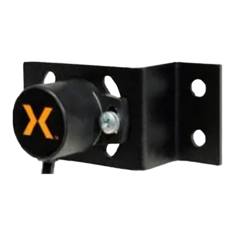
A. Secure "PH20" to threaded extension of adjustment
screw of Mounting Bracket (See Figs. 2 & 3).
B. Secure Mounting Bracket to customer supplied
sensor mounting bar (1 in. [25 mm] square ) mounted
across web (See Fig. 4).
II.II.
II.II.
II. ELECTRICAL CONNECTIONSELECTRICAL CONNECTIONS
ELECTRICAL CONNECTIONSELECTRICAL CONNECTIONS
ELECTRICAL CONNECTIONS
A. "PH20" comes with a 16 ft. [5 m], 4 conductor,
shielde d cable. Connect wiring to W e b Guide Amplifier according to instructions provided with
Amplifier (See Fig. 6 for color coding and
significance of wires).
NOTENOTE
NOTENOTE
NOTE
Make sure lock nut on threaded extension is tightMake sure lock nut on threaded extension is tight
Make sure lock nut on threaded extension is tightMake sure lock nut on threaded extension is tight
Make sure lock nut on threaded extension is tight
against "PH20"against "PH20"
against "PH20"against "PH20"
against "PH20"
C. Make sure Sensor is securely mounted on Mounting
Bracket, and Mounting Bracket is securely mounted
to machine . Looseness in these mountings will
cause Sensor movement and prevent accurate
edge guiding.
FIGURE 3FIGURE 3
FIGURE 3FIGURE 3
FIGURE 3
BarBar
BarBar
Bar
AdjustmentAdjustment
AdjustmentAdjustment
Adjustment
Screw LockScrew Lock
Screw LockScrew Lock
Screw Lock
Hex.Hex.
Hex.Hex.
Hex.
AdjustmentAdjustment
AdjustmentAdjustment
Adjustment
ScrewScrew
ScrewScrew
Screw
AdjustmentAdjustment
AdjustmentAdjustment
Adjustment
Screw LockScrew Lock
Screw LockScrew Lock
Screw Lock
Adjustment ScrewAdjustment Screw
Adjustment ScrewAdjustment Screw
Adjustment Screw
Clamping ScrewsClamping Screws
Clamping ScrewsClamping Screws
Clamping Screws
FIGURE 5FIGURE 5
FIGURE 5FIGURE 5
FIGURE 5
Install Support Bar onInstall Support Bar on
Install Support Bar onInstall Support Bar on
Install Support Bar on
either side (rewind).either side (rewind).
either side (rewind).either side (rewind).
either side (rewind).
Support Bar must be partSupport Bar must be part
Support Bar must be partSupport Bar must be part
Support Bar must be part
of Rewind Stand.of Rewind Stand.
of Rewind Stand.of Rewind Stand.
of Rewind Stand.
Install Support Bar onInstall Support Bar on
Install Support Bar onInstall Support Bar on
Install Support Bar on
either side (unwind).either side (unwind).
either side (unwind).either side (unwind).
either side (unwind).
Support Bar must be partSupport Bar must be part
Support Bar must be partSupport Bar must be part
Support Bar must be part
of Main Machine Frame.of Main Machine Frame.
of Main Machine Frame.of Main Machine Frame.
of Main Machine Frame.
Install Support Bar onInstall Support Bar on
Install Support Bar onInstall Support Bar on
Install Support Bar on
either side (mid-process).either side (mid-process).
either side (mid-process).either side (mid-process).
either side (mid-process).
Last MachineLast Machine
Last MachineLast Machine
Last Machine
RollRoll
RollRoll
Roll
Roll attached toRoll attached to
Roll attached toRoll attached to
Roll attached to
Unwind StandUnwind Stand
Unwind StandUnwind Stand
Unwind Stand
First MachineFirst Machine
First MachineFirst Machine
First Machine
RollRoll
RollRoll
Roll
Guide RollGuide Roll
Guide RollGuide Roll
Guide Roll
MechanismMechanism
MechanismMechanism
Mechanism
Attachment HolesAttachment Holes
Attachment HolesAttachment Holes
Attachment Holes
FIGURE 2FIGURE 2
FIGURE 2FIGURE 2
FIGURE 2
NOTENOTE
NOTENOTE
NOTE
When positioning "PH20", make sure web passesWhen positioning "PH20", make sure web passes
When positioning "PH20", make sure web passesWhen positioning "PH20", make sure web passes
When positioning "PH20", make sure web passes
through light beam at an angle of 5 to 45 degrees fromthrough light beam at an angle of 5 to 45 degrees from
through light beam at an angle of 5 to 45 degrees fromthrough light beam at an angle of 5 to 45 degrees from
through light beam at an angle of 5 to 45 degrees from
perpendicular (See Fig. 5).perpendicular (See Fig. 5).
perpendicular (See Fig. 5).perpendicular (See Fig. 5).
perpendicular (See Fig. 5).
Angle must beAngle must be
Angle must beAngle must be
Angle must be
55
55
5oo
oo
oor greateror greater
or greateror greater
or greater
FIGURE 4FIGURE 4
FIGURE 4FIGURE 4
FIGURE 4
FIGURE 6FIGURE 6
FIGURE 6FIGURE 6
FIGURE 6
"PH20" Schematic Diagram"PH20" Schematic Diagram
"PH20" Schematic Diagram"PH20" Schematic Diagram
"PH20" Schematic Diagram
Cds
Cds
Halfmirror
Lamp
8 Black
3 White
7 Red
1 Green
2 Brown
4 Shield
Reflector
