8FORM NO. L-20334-C-0404
OPERATION
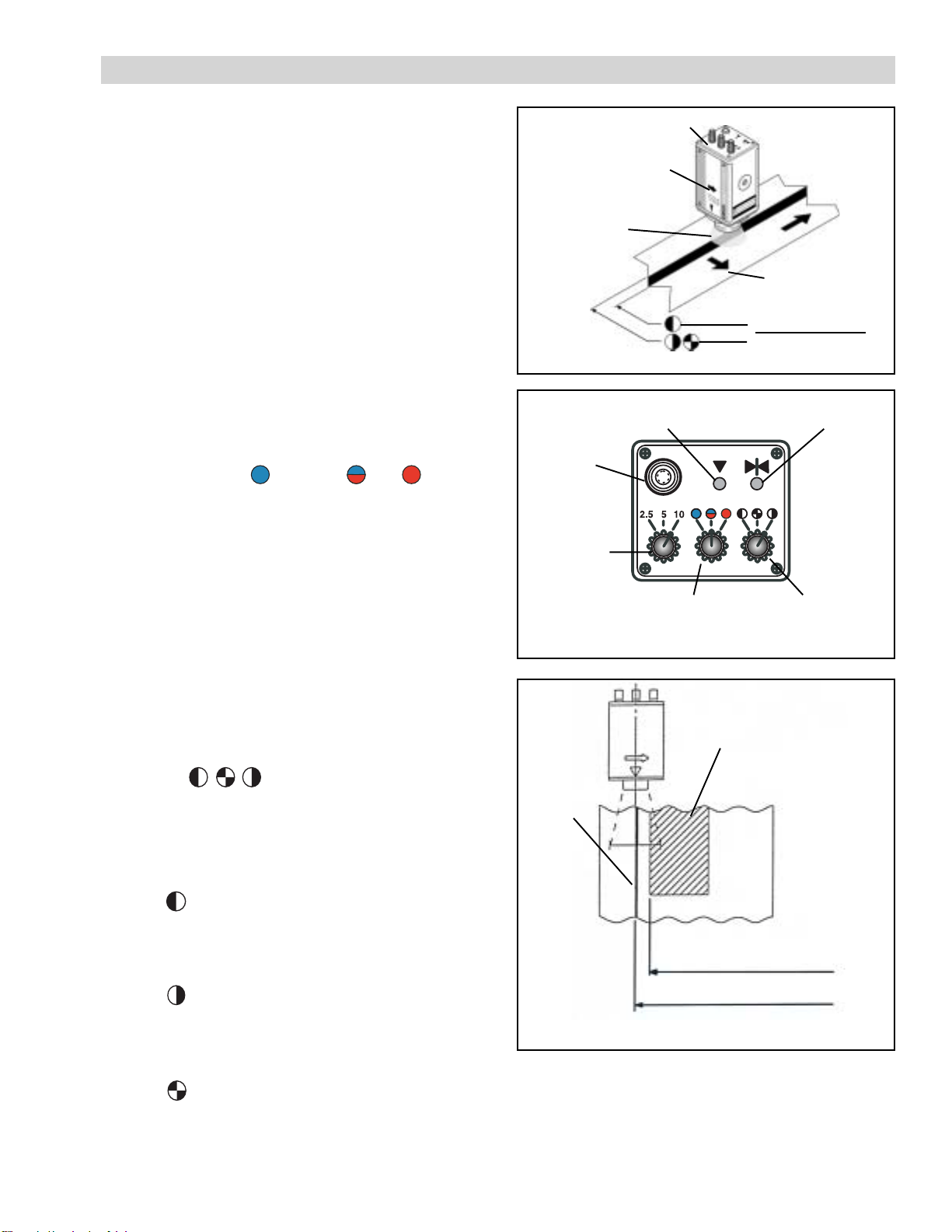
FIGURE10
Left Edge
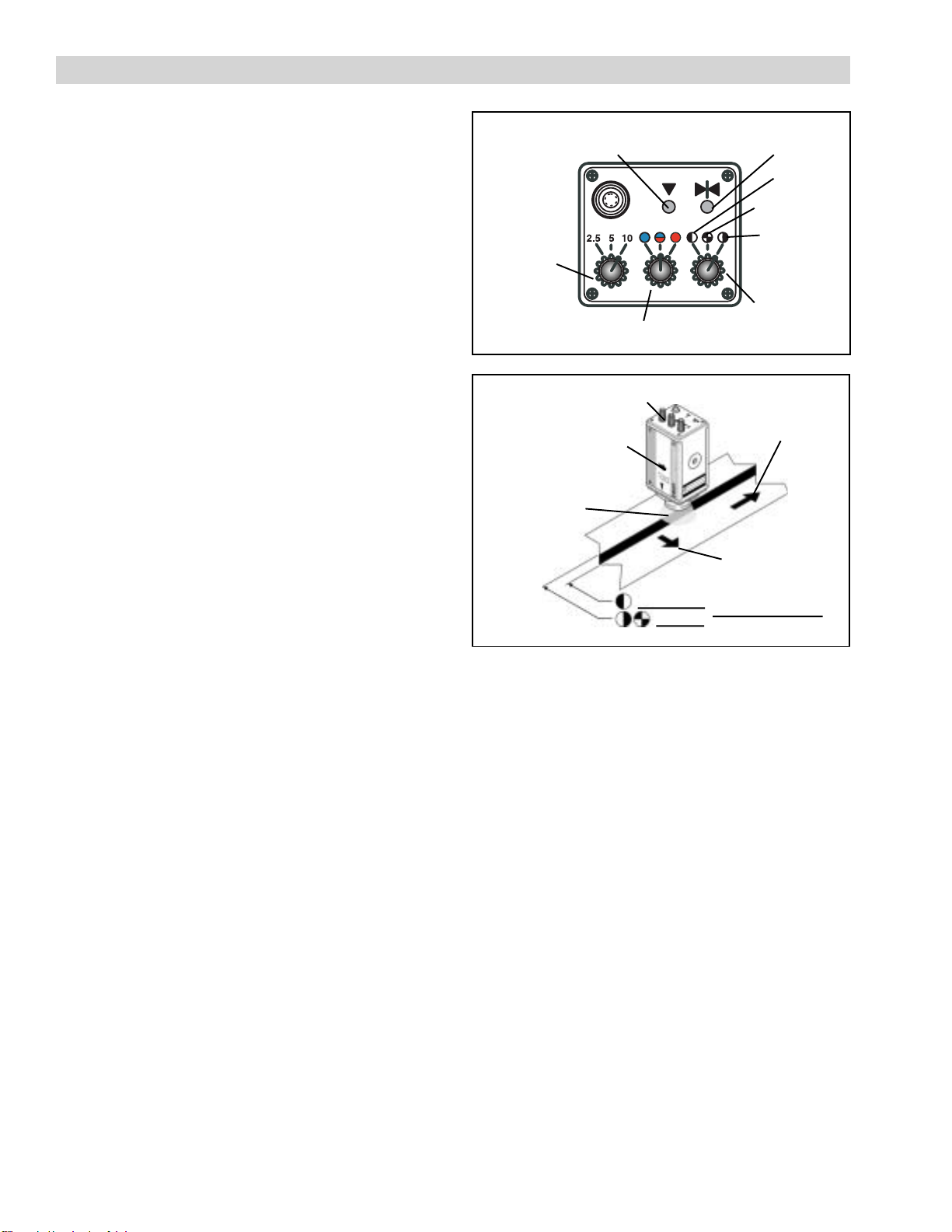
FIGURE11
Focal
Display Indicator Center
Display Indicator
Field-of-View
Switch
Color Selector Switch
Contrast
Selector
Switch
Line Follower Head
ScanningDirection
Indicator Arrow
Field of
View
Scanning
Direction
Detection Position
Detection Position
Web
Direction
Right Edge
First Edge
DESCRIPTION
The LH100 scans in the direction of the arrow printed on
its side (See Figure 11). The LH100 looks for a target
edge within its field of view that matches the setting
made with the Field-of-View Switch (See INDICATORS
AND SWITCHES section). When the target edge is not
centered within the field of view, the LH100 will output a
control signal that will vary in proportion to how far the
target edge is away from center. Each setting of the
Field-of-View Switch has a different output voltage
range. The center of the range corresponds to the target
edge being centered within the field of view.
When a target edge moves from center, the output
voltage will change until the edge leaves the field of
view. This output voltage will remain constant until the
target returns to the field of view. This will allow the web
guide to continue steering the target edge back to
center of the field of view. If the Actuator Lock function
is used, then the web guide will maintain its position at
the instant the target edge leaves the field of view until
the target edge returns.
ACTUATOR LOCK FUNCTION
The Actuator Lock Function automatically turns on the
Actuator Lock Output Transistor whenever the Focal
Display Indicator turns off. The following situations will
cause the Focal Display Indicator to turn off: web or line
edge moving outside the field of view, a break in the line
edge, or improper positioning of the LH100.
Use the Actuator Lock output signal for instances where
there are breaks in the target line or edge that will
reappear quickly. This function will prevent the web
guide from moving out of position while waiting for the
line or edge to reappear.
Do not use the Actuator Lock Function for instances
when the edge moves out of the field of view in a
direction perpendicular to web travel and it is desired to
have the web guide controller steer the edge back.
SETUP
1. Set the Field Of View, Color, and Contrast Selector
switches to appropriate positions.
2. Center the LH100 directly over the line or web edge
and adjust the vertical distance of the LH100 to the web
surface until the Focal Display indicator turns on (See
Figures 10 and 11). For highly reflective webs, be sure
the Diffuser Cap is installed and positioned about 1 mm
[0.04 in] above the web for proper focus (See Figure 4).
3. Adjust the lateral position of the LH100 until the
Center Display indicator turns on and indicates the
center of the field of view is aligned with the appropriate
line, pattern or web edge (See Figures 10 and 11).
4. Calibrate the LH100 to the web guide controller by
referring to the controller’s instruction manual.
5. Test the system setup by slowly pulling the web,
causing the line or edge to move within LH100 field of
view. The LH100 output should cause the web guide to
move in the opposite direction of web movement. This
will bring the line/edge back to center.
6. Disable the Actuator Lock Signal and pull the web
edge or line slowly until it leaves the LH100’s field of
view (the focal display indicator turns off). The web guide
should continue to steer, until it reaches an end-of-travel
limit, in an attempt to move the edge or line back to the
center of the field of view.
7. Enable the Actuator Lock Signal and slowly pull the
web edge or line away from the LH100 until it leaves the
LH100’s field of view (the focal display indicator turns
off). The web guide should stop moving once the line or
edge moves beyond the field of view.