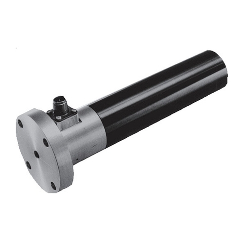
Nexen PH30P User manual

1FORM NO. L-20153-B-0603
WEB CONTROL PRODUCTS
User Manual
Web Guide Sensors
Models PH30P and PH11P

2FORM NO. L-20153-B-0603
In accordance with Nexen’s established policy of constant product improvement, the specifications contained in this
manual are subject to change without notice. Technical data listed in this manual are based on the latest information
available at the time of printing and are also subject to change without notice.
Technical Support: 800-843-7445
(651) 484-5900
www.nexengroup.com
Copyright 1999 Nexen Group, Inc.
Nexen Group, Inc.
560 Oak Grove Parkway
Vadnais Heights, Minnesota 55127
ISO 9001 Certified
Read this manual carefully before installation and operation.
Follow Nexen's instructions and integrate this unit into your system with care.
This unit should be installed, operated and maintained by qualified personnel ONLY.
Improper installation can damage your system or cause injury or death.
Comply with all applicable codes.
DANGER

3FORM NO. L-20153-B-0603
TABLEOFCONTENTS
Introduction----------------------------------------------------------------------------------------------------------------------------------------1
Installation ---------------------------------------------------------------------------------------------------------------------------------------- 2
Electrical Connections -----------------------------------------------------------------------------------------------------------------------3
Air Purge Connections -----------------------------------------------------------------------------------------------------------------------3
Tuning & Calibration ---------------------------------------------------------------------------------------------------------------------------3
Maintenance-------------------------------------------------------------------------------------------------------------------------------------- 3
Specifications------------------------------------------------------------------------------------------------------------------------------------4
Replacement Parts ----------------------------------------------------------------------------------------------------------------------------6
Parts List ------------------------------------------------------------------------------------------------------------------------------------------- 6
Warranties-----------------------------------------------------------------------------------------------------------------------------------------7

4FORM NO. L-20153-B-0603
INTRODUCTION
Read this manual carefully, making full use of its explanations and instructions. The “Know How” of safe, continuous,
trouble-free operation depends on the degree of your understanding of the system and your willingness to keep all
components in proper operating condition. Pay particular attention to all NOTES, CAUTIONS, and WARNINGS to avoid
the risk of personal injury or property damage. It is important to understand that these NOTES, CAUTIONS, and
WARNINGS are not exhaustive. Nexen cannot possibly know or evaluate all conceivable methods in which service may
be performed, or the possible hazardous consequences of each method. Accordingly, anyone who uses a procedure
that is not recommended by Nexen must first satisfy themselves that neither their safety or the safety of the product will
be jeopardized by the service method selected.
Nexen’s PH30P and PH11P are electrical photo sensors
designed for use with a web guide amplifier, and are
used to sense the edge of an opaque web of material by
using a light beam in the normal visual spectrum. The
center of this light beam is the desired position of the
web.
The sensor is composed of a lamp housing and a sensor
housing separated by a mounting bar. The length of this
mounting bar is the primary difference between PH30P,
and PH11P. Both units are provided with air purge
fittings which allow low pressure air, 28 to 85 psi (2 to 6
kg/CM2) to be directed across the lamp and sensor
lenses to keep them clear in a dusty or dirty atmosphere.
PH30P
Transport
Rollers
FIGURE 1
PH30P
A
FIGURE 2 (Unwind Roll)
PH30P
A
FIGURE 3 (Wind Up Roll)
PH30P is designed for normal applications where the
web pass line is constant., as is always the case in mid-
process web guiding where the web is supported by
web transport rollers before it enters, and after it leaves
the sensor (See Fig. 1). The pass line will also be
constant if roll Ais present on an unwind or winding
stand (See Figs. 2 & 3). If roll Ais not present, PH11P
must be used because the web path will vary vertically
as the wind or unwind roll changes diameter. The wide
distance between the lamp housing and sensor housing
on PH11P will accommodate the change in web
position. PH11P is also equipped with guard plates to
prevent the web from contacting the lamp lens or sensor
lens.

5FORM NO. L-20153-B-0603
INSTALLATION
1. Vertically mount both PH30P and PH11P with
the sensor housing at the top and the lamp housing
at the bottom, in order to eliminate ambient light
from the sensor (See Figs. 4 & 5).
2. Mount sensor solidly with mounting holes provided
in sensor. If the web edge position must be
changed from time to time, provisions must be made
to change sensor position.
FIGURE 4
Sensor
Housing
0.75" [19 mm]
Mounting
Holes
Lamp
Housing
0.75" [19 mm]
Mounting Holes
Sensor
Housing
Lamp
Housing
PH30P PH11P
FIGURE 5
AEnd Pivot
Guide Roll
Unwind Sensor
PH30P End Pivot
Sensor
Center Pivot
Guide Rolls
Center Pivot
Sensor
Windup Sensor
PH30P
A
NOTE: Sensor must be firmly mounted or it will
change position due to machine vibration. If this
happens, the center point of the sensor will change
and the web will be moved to the new sensor
position.
Extra transport rollers between sensor
and roll stand or guide roll mechanism
it is trying to control will cause a time
lag in web guide correction. This time
lag will cause hunting (See Fig. 5).

6FORM NO. L-20153-B-0603
ELECTRICAL CONNECTIONS
1. Remove male cable end connector from Lamp
Housing. Using customer supplied 18 AWG
shielded cable, connect pins Aand Bto terminals 1
and 2(See Fig. 6).
2. Remove female cable end connector from Sensor
Housing. Using customer supplied 18 AWG
shielded cable, connect pins Aand Bto terminals 3
and 4(See Fig. 6).
NOTE: Maximum cable length is 130 ft. [40 m].
3. Connect both shield wires to terminal 4(See Fig. 6).
Lamp
Housing
Connector
Detector
Housing
Connector
AE80
Terminal
Block
FIGURE 6
AIR PURGE CONNECTIONS
1. Purging air passes over lamp and sensor lenses to
keep them clean. Install air filtration as required to
remove impurities from plant air supply (See Fig. 7)
To Air Purge Inlet, Lamp Housing
To Air Purge Inlet, Sensor Housing
Filter, as needed to remove dirt and moisture from air.
Regulator, reduces plant air pressure to approx. 30 psi [2 kg/cm2]
FIGURE 7
2. Install air pressure regulator to reduce plant air to
approximately 30 psi [2 Kg/CM2], at a rate of 15
SCM [400 NL/min.] (See Fig. 7).
TUNING & CALIBRATION
All tuning and calibration is done at the controller, not
the photo sensor. Refer to appropriate Maintenance and Illustration Manual
for Web Guide Amplifier being used.
MAINTENANCE
No periodic or scheduled maintenance is required for
either PH30P or PH11P. The only replaceable items are
the Lamp Assembly and the Sensor Assembly.
LAMP REPLACEMENT (See Fig. 8)
1. Remove four Phillips Head Screws (Item 18) and
Washers (Item 17).

7FORM NO. L-20153-B-0603
Lamp Voltage 12VDC, supplied by Web Guide Amplifier
Output
Output 0-500 mVDC depending on web position within light path.
Sensitivity 0.004" [0.1 mm] web movements can be sensed (opaque webs only)
Air 15 SCFM (400 ml/mm) @ 30 psi [2 kg/CM2]
Consumption
Temperature 14oto 140o F [-10oto +60oC]
Range
17
18
13
20 21
22
15
16 23
24
FIGURE 8
SENSOR REPLACEMENT (See Fig. 9)
1. Remove four Phillips Head Screws (Item 1) and
Washer (Item 2).
2. Remove Sensor Housing Cover (Item 9) and Gasket
(Item 10).
3. Remove two Phillips Head Screws (Item 3) and
Washers (Item 4).
4. Remove Sensor Cover (Item 5).
5. Mark and desolder wire leads from old Sensor unit
(Silicone Photo Diode SPD).
6. Replace SPD and resolder wire leads.
NOTE: Maintain wire polarity per marks made in
Step 4.
7. Reverse Steps 4through 1 to reassemble Detector
Housing
4
5
3
9
2
1
10
FIGURE 9
Mark and
desolder
wire leads.
2. Remove Lamp Housing Cover and Gasket (Items 23
& 24).
3. Remove two Phillips Head Screws (Item 16) and
Washers (Item 15).
4. Remove Lamp Connector (Item 22).
5. Remove two Phillips Head Screws (Item 21) and
Washers (Item 20).
6. Remove and replace Lamp Assembly (Item 13).
7. Reverse above procedure to reassemble Lamp
Housing.
SPECIFICATIONS

8FORM NO. L-20153-B-0603
FIGURE 11
PH11P Mounting Dimensions
FIGURE10
PH30PMountingDimensions

9FORM NO. L-20153-B-0603
REPLACEMENT PARTS
The item or balloon number for all Nexen products is used
for part identification on all product parts lists, product
price lists, unit assembly drawings, bills of materials, and
instruction manuals.
When ordering replacement parts, specify model
designation, item number, part description, and quantity.
Purchase replacement parts through your local Nexen
Distributor.
PARTS LIST
The item or balloon number for all Nexen products is
used for part identification on all product parts lists,
product price lists, unit assembly drawings, bills of
materials, and instruction manuals.
ITEM DESCRIPTION P/N QTY.
1 Lamp Assembly 2849 1
2 Sensor Assembly 2850 1
Item 1
Lamp
Assembly
Item 2
Sensor
Assembly
FIGURE12

10FORM NO. L-20153-B-0603
WARRANTIES
Warranties
Nexen warrants that the Products will be free from any defects in material or workmanship for a period of 12 months
from the date of shipment. NEXEN MAKES NO OTHER WARRANTY, EXPRESS OR IMPLIED, AND ALL IMPLIED
WARRANTIES, INCLUDING WITHOUT LIMITATION, IMPLIED WARRANTIES OF MERCHANTABILITY AND
FITNESS FOR A PARTICULAR PURPOSE ARE HEREBY DISCLAIMED. This warranty applies only if (a) the Product
has been installed, used and maintained in accordance with any applicable Nexen installation or maintenance manual
for the Product; (b) the alleged defect is not attributable to normal wear and tear; (c) the Product has not been altered,
misused or used for purposes other than those for which it was intended; and (d) Buyer has given written notice of the
alleged defect to Nexen, and delivered the allegedly defective Product to Nexen, within one year of the date of
shipment.
Exclusive Remedy
The exclusive remedy of the Buyer for any breach of the warranties set out above will be, at the sole discretion of Nexen,
a repair or replacement with new, serviceably used or reconditioned Product, or issuance of credit in the amount of the
purchase price paid to Nexen by the Buyer for the Products.
Limitation of Nexen’s Liability
TO THE EXTENT PERMITTED BY LAW NEXEN SHALL HAVE NO LIABILITY TO BUYER OR ANY OTHER PERSON
FOR INCIDENTAL DAMAGES, SPECIAL DAMAGES, CONSEQUENTIAL DAMAGES OR OTHER DAMAGES OF
ANY KIND OR NATURE WHATSOEVER, WHETHER ARISING OUT OF BREACH OF WARRANTY OR OTHER
BREACH OF CONTRACT, NEGLIGENCE OR OTHER TORT, OR OTHERWISE, EVEN IF NEXEN SHALL HAVE
BEEN ADVISED OF THE POSSIBILITY OR LIKELIHOOD OF SUCH POTENTIAL LOSS OR DAMAGE. For all of
the purposes hereof, the term “consequential damages” shall include lost profits, penalties, delay images, liquidated
damages or other damages and liabilities which Buyer shall be obligated to pay or which Buyer may incur based upon,
related to or arising out of its contracts with its customers or other third parties. In no event shall Nexen be liable for
any amount of damages in excess of amounts paid by Buyer for Products or services as to which a breach of contract
has been determined to exist. The parties expressly agree that the price for the Products and the services was
determined in consideration of the limitation on damages set forth herein and such limitation has been specifically
bargained for and constitutes an agreed allocation of risk which shall survive the determination of any court of
competent jurisdiction that any remedy herein fails of its essential purpose.
Limitation of Damages
In no event shall Nexen be liable for any consequential, indirect, incidental, or special damages of any nature whatso-
ever, including without limitation, lost profits arising from the sale or use of the Products.
Warranty Claim Procedures
To make a claim under this warranty, the claimant must give written notice of the alleged defect to whom the Product
was purchased from and deliver the Product to same within one year of the date on which the alleged defect first
became apparent.
Nexen Group, Inc.
560 Oak Grove Parkway
Vadnais Heights, MN 55127
800.843.7445
Fax: 651.286.1099
www.nexengroup.com
ISO 9001 Certified
This manual suits for next models
1
Table of contents
Other Nexen Accessories manuals

Nexen
Nexen AIR CHAMP LSCC-32 User manual

Nexen
Nexen WEB CONTROL PH 16 User manual

Nexen
Nexen CFL User manual

Nexen
Nexen DPS60A Dual User manual

Nexen
Nexen GC300 User manual

Nexen
Nexen WEB CONTROL LH100 User manual

Nexen
Nexen DPS30 User manual

Nexen
Nexen AIR CHAMP LSCC-32 User manual

Nexen
Nexen PH20 Technical Document