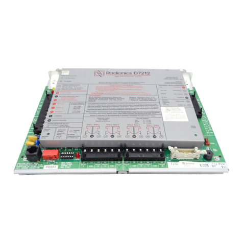
Radionics D9124 Specification sheet

R A D I O N I C S
D9124 Addressable 24 VDC Control/Communicator
Operation and Installation Manual
© 1996 Radionics
74-06799-000-D 2/96
www.PDF-Zoo.com
firealarmresources.com

D9124 Operation & Installation Manual
Page 2
© 1995 Radionics
74-06799-000-D 2/95
Notice
The material and instructions covered in this manual have been carefully checked for
accuracy and are presumed to be reliable. However, Radionics Inc. assumes no
responsibility for inaccuracies and reserves the right to modify and revise this manual
without notice.
It is our goal at Radionics to always supply accurate and reliable documentation. If a
discrepancy is found in this documentation, please mail a photocopy of the corrected
material to:
Radionics, Inc.,
c/o Technical Writing Dept.
1800 Abbott Street
P.O. Box 80012
Salinas, CA 93912-0012
©1995 Radionics, Inc., Salinas, CA, U.S.A. All rights reserved.
FCC Notices
Part 15
This equipment has been tested and found to comply with the limits for a Class B digital
device, pursuant to Part 15 of the FCC Rules. These limits are designed to provide
reasonable protection against harmful interference in a residential installation. This
equipment generates, uses and can radiate radio frequency energy, and, if not installed
in accordance with the instructions, may cause harmful interference to radio communica-
tions. However, there is no guarantee that interference will not occur in a particular
installation. If this equipment does cause harmful interference to radio or television
reception, which can be determined by turning the equipment on and off, the user is
encouraged to try to correct the interference by one or more of the following measures:
1) Reorient or relocate the receiving antenna
2) Increase the separation between the equipment and the receiver
3) Connect the equipment into an outlet on a circuit different from that to which the
receiver is connected.
4) Consult the dealer or an experienced radio/TV technician for help.
Part 68
This equipment complies with Part 68 of FCC Rules. A label contains, among other
information, the FCC registration number and ringer equivalence number (REN). If
requested, this information must be provided to the telephone company.
The Radionics D9124 24 VDC Addressable Fire System is registered for connection to
the public telephone network using an RJ38X or RJ31X jack.
The ringer equivalence number (REN) is used to determine the quantity of devices that
may be connected to the telephone line. Excessive devices on the telephone line may
result in one or more devices not ringing in response to an incoming call. In most, but not
all areas, the sum of the RENs should not exceed five (5). To be certain of the number of
devices that may be connected to the line, as determined by the RENs, contact the
telephone company to determine the maximum REN for the calling area.
www.PDF-Zoo.com
firealarmresources.com

D9124 Operation & Installation Manual
Page 3
© 1995 Radionics
74-06799-000-D 2/95
Part 68 (continued)
If the D9124 System causes harm to the telephone network, the telephone company may
notify you or the customer as soon as possible. Also, you will be advised of your right to
file a complaint with the FCC if you believe it is necessary.
The telephone company may make changes in its facilities, equipment, operations, or
procedures that could affect the operation of the equipment. If this happens, the
telephone company will provide advance notice in order for you to make the necessary
modifications in order to maintain uninterrupted service.
If trouble is experienced with the D9124 Control Panel, please contact Radionics
Customer Service for repair and/or warranty information. If the trouble is causing harm to
the telephone network, the telephone company may request that you remove the
equipment from the network until the problem is resolved. User repairs must not be
made, and doing so will void the equipment’s warranty.
This equipment cannot be used on public coin service provided by the telephone
company. Connection to the Party Line service is subject to state tariffs. (Contact your
state public utilities commission for information.)
FCC Registration Number AJ9USA-18808-AL-E
Ringer Equivalence 0.1A 0.2B
Service Center in U.S.A. Radionics, Inc.
1800 Abbott Street
P.O. Box 80012
Salinas, CA 93912-0012
(800) 538-5807
UL/NFPA Notices
UL listed for NFPA 72 Central Station, Local, Auxiliary, Remote Station, Household Fire
Warning Systems. The D9124 System has been approved by FM, NYC-MEA and CSFM.
The D9124 System is also listed for certificated central station Grade B and Grade C
burglary applications. Grade B systems require a local bell. The D1255 Command Center
is needed to meet the requirement of UL Central Burglary requirements.
All references to NFPA and related requirements
are based upon compliance with the
1993 edition of NFPA 72, National Fire Alarm Code. Since installation specifications are
nearly always based upon a specific edition of a standard which has been legally adopted
by the Authority Having Jurisdiction (AHJ), earlier editions of NFPA standards will
generally apply. Consult with the appropriate AHJ for confirmation.
www.PDF-Zoo.com
firealarmresources.com

D9124 Operation & Installation Manual
Page 4
© 1995 Radionics
74-06799-000-D 2/95
Table of Contents
Notice ............................................................... 2
FCC Notices ..................................................... 2
Safety Section ....................................................... 5
D9124 and High Voltage .................................. 5
Safety Precautions While Handling Batteries ... 5
Introduction ........................................................... 6
Protective Points............................................... 6
Communicator .................................................. 6
Event Logger .................................................... 6
Time and Date .................................................. 6
Skeds (scheduled events) ................................ 7
Local Printer ..................................................... 7
EMI/Lightning Transient Protection .................. 7
Programming .................................................... 7
Other Features ................................................. 7
Before You Begin ............................................. 7
Installation ............................................................. 8
D9124 Assembly .............................................. 8
Mounting the D9101 Enclosure ......................10
Installing the D1601 Transformer ................... 11
Connecting the Earth Ground......................... 12
Connecting the 120 VAC Power Input............ 12
Installing Battery Shelves and
Transformer Cover ......................................... 13
Mounting the Components ............................. 14
Mounting Additional Modules ......................... 14
Connecting Cables Between D9124 System
Components ................................................... 14
Wiring Additional Modules .............................. 16
Turning on the Power ..................................... 16
Command Centers and Annunciation
Devices................................................................. 17
Descriptions.................................................... 17
Installing Command Centers and
Annunciators................................................... 18
D1256/D1257 Specifications .......................... 19
Indicating Circuit (24 VDC Horns,
Strobes, Bells) ..................................................... 20
Description...................................................... 20
Operation ........................................................ 20
Silence Switch ................................................ 20
ZONEX, Addressable Points .............................. 21
Description...................................................... 21
Connecting the Additional D8125 Module ...... 22
Selecting POPIT Point Assignments .............. 22
Installing POPITs............................................ 23
Wiring the POPIT Sensor Loop ......................26
Connecting Data Loops to Terminals
on the Motherboard ........................................26
Central Station Reports .................................. 27
Power Supply ...................................................... 28
Power for the D9112LTB, Command
Center and Modules ....................................... 28
Installing the 12V Standby Source Batteries .. 29
Power for 24 VDC Initiating and
Indicating Devices (D9142) ............................ 30
Installing the 24V Standby Source Batteries .. 31
D9142 24 VDC Power Supervision ................ 32
Power Output....................................................... 33
Auxiliary Power Outputs .................................33
Alarm Power Output for Indicating Circuits..... 34
Auxiliary Current and Standby
Battery Requirements......................................... 35
Calculations for 12 VDC Devices ................... 35
Calculations for 24 VDC Devices ................... 36
Standby Battery Calculations For
Fire Alarm Applications...................................... 37
Calculations for D9112LTB and 12 VDC
Initiating and Indicating Devices ..................... 37
Calculations for D9142 Power Supply and
24 VDC Initiating and Indicating Devices ....... 38
Telephone Connections ..................................... 39
D928 Dual Phone Line Switcher..................... 39
Communication Failure................................... 41
Registration .................................................... 41
Notification...................................................... 41
Location .......................................................... 42
Phone Line Select Switch ............................... 42
Programming....................................................... 43
Programming the Panel.................................. 43
Unlock the Reset Pin ...................................... 43
Programmable Test Features......................... 44
Testing The System ............................................ 46
Fire Test ......................................................... 46
Service Walk Test........................................... 47
Troubleshooting Guide....................................... 48
Introduction..................................................... 48
Self Diagnostics.............................................. 48
Phone Line Trouble ........................................50
Communications Failure ................................. 51
Problems Programming the Panel.................. 52
Problems with Points ...................................... 53
Problems with the D8125 POPEX Data
Expansion Loops ............................................ 56
Checking Shielded Cable ...............................57
EMI on Long Wire Runs ................................. 57
Problems with Command Centers.................. 58
Watchdog Reset Reports ............................... 59
Runaway Reports to the Receiver.................. 59
Battery and Power Reports ............................ 59
Overloaded 12 Volt Power Supply.................. 60
120 VAC Fuse ................................................ 61
D9124 24VDC Power Supply .............................. 62
Specifications, D9142 ......................................... 64
Specifications, D9124 ......................................... 65
www.PDF-Zoo.com
firealarmresources.com

D9124 Operation & Installation Manual
Page 5
© 1995 Radionics
74-06799-000-D 2/95
J5
J8
XFRM
F1
TO 120 VAC HIGH
VOLTAGE SOURCE
DANGER!
120 VAC
HOT NEUT GND
1 2 3
Figure 1: High Voltage On D9142
Safety Section
D9124 and High Voltage
The D9124 System connects directly to a 20 Amp, single phase circuit breaker. The high
voltages at these connections are extremely dangerous. Only licensed electricians should
make or service these connections.
Ground the System First
For safety and to help prevent damage from
electrostatic charges or other transient
electrical surges, connect the green
ground wire for the 120 VAC to the
stud shown in
Figure 6
before making
any other connections to the panel.
Also connect the two green panel
earth ground wires to the earth
ground stud. All connections to the
ground stud must be made exactly
as shown in
Figure 5
.
All connections to the 120 VAC
terminals should be performed
as directed by NEC 70.
Safety Precautions While
Handling High Voltage
Danger!
High voltage is present
at the AC Power input terminals,
at Fuse F1, and at connector J8,
near the lower right corner of the
D9142 Power Supply (see
Figure 1
). Always use the dedicated circuit breaker to remove 120 VAC before removing
the covers to the fuse or terminals block. The terminals and fuse must be covered after
making connections or testing these connections.
Safety Precautions While Handling Batteries
Wear rubber gloves and safety goggles while connecting batteries together. Mixing
batteries of different battery capacities, or mixing batteries from multiple manufacturers is
not recommended.
Unplug the D9142 battery connector J7 before attaching or removing wires at the D9142
Power Supply’s terminals.
Refer to battery manufacturer instructions for further information about batteries and
applicable safety precautions.
www.PDF-Zoo.com
firealarmresources.com

D9124 Operation & Installation Manual
Page 6
© 1995 Radionics
74-06799-000-D 2/95
Introduction
Protective Points
As shipped, the Radionics D9124 Addressable 24 VDC System provides eight on-board
points built into the panel. On-board points 7 and 8 support a 24 volt power supply and
notification circuits, and are not for other uses. As shipped, the panel can support 63 added
POPITs. In addition, if you use an additional D8125 POPEX Module, another 63 points can
be added, for a maximum total of 134 (8+63+63). Each point requires an addressable
device for individual annunciation, such as the D462, D290S, D290M, or a POPIT. Each
point is programmed separately with options to custom-fit the protection to your installation.
Point programming parameters determine the system’s response to open and shorted
conditions on the sensor loop.
Communicator
The D9124 Addressable 24 VDC System uses a built-in digital communicator to send
reports to the receiver. Up to four receiver phone numbers can be programmed. You can
program the panel to send reports to primary, backup, and duplicate phone destinations.
The panel transmits reports in either Modem or BFSK format. It is recommended that you
use the Modem format to provide full system information to the receiver.
The D9124 System connects to two D166 RJ31X (or RJ38X) jacks for phone line seizure.
Connection to the jacks complies with FCC regulations for using the public telephone
network. The D9124 System uses the built-in D928 Dual Phone Line Switcher to supervise
two phone lines.
24 Volt DC Outputs
The D9124 Control Communicator provides a 24 volt DC power supply. This power supply
is rated at 4 amps. The operating voltage range of this output is from 18.9 VDC to 28 VDC.
All Radionics 24 volt indicating devices are compatible with this power supply. For other
indicating and initiating devices refer to the manufacturer’s installation instructions and verify
the devices minimum operating voltage is equal to or less than 18.9 volts DC and the
maximum operating voltage is equal to or greater than 28 volts DC.
Important: Connection of 24 volt indicating and initiating devices that have a
minimum operating voltage greater than 18.9 VDC or a maximum operating voltage
less than 28 volts DC may be damaged or fail to operate!
Time and Date
To set the time and date you need a D1255 Command Center or RAM II.
Event Logger
The D9124 System stores up to 500 system events and event modifiers in its Event log.
Event modifiers add information about an event to the log. Some events are always followed
by a modifier. For example, the D9124 System adds at least two items to the log each time
it reports a phone line failure or keypad failure. It sends the event name and then an event
modifier showing the number of the failed device.
All events and their modifiers are stored even if the D9124 System does not send a report
for them. You can view the log at a D1256 Fire Command Center, print it locally using the
D9131 Parallel Printer Interface and a parallel printer, or upload it to a D5300 Remote
Account Manager II (RAM II).
www.PDF-Zoo.com
firealarmresources.com

D9124 Operation & Installation Manual
Page 7
© 1995 Radionics
74-06799-000-D 2/95
Skeds (scheduled events)
The Skeds feature of the D9124 System uses the panel’s internal clock and calendar.
Each Sked is programmed for a time, and either a day of the week schedule or a date of the
year schedule. The user can change the time a Sked occurs if it is programmed for time
editing.
For example, the D9124 System can use the Skeds for a service reminder feature. In this
application, a system fault that activates the panel trouble sounder can be acknowledged
and the sounder silenced. Skeds and an optional D8129 Relay Module can then be used to
reactivate the panel trouble sounder on a daily or weekly basis until the system fault is
corrected.
Local Printer
The D9124 System can print events recorded on a standard parallel printer, using the D9131
Parallel Printer Interface. The D9131 uses an 80 character print format. The format includes
the time, date, account number, event, point number, and point text. The 80 character format
also provides additional system status information.
EMI/Lightning Transient Protection
The D9124 System maintains the Radionics high level of quality and field dependability. Its
design significantly reduces electromagnetic interference and malfunction generally caused
by lightning.
Programming
Use the Radionics D5200 Programmer, or the D5300 Remote Account Manager II (RAM II)
to program the D9124 System. You must use D9112 handlers. See
Programming
in this
manual for parameters. The D9124 System comes from the factory with a partial program
already loaded. It is necessary for you to complete this program in order for the D9124
System to function. The
D9124 Program Record Training Sheet
(74-06802-000) contains the
program entries that are loaded into a new D9124 System before it’s shipped from the
factory. Radionics recommends that you copy the program from a new D9124 System. Save
and lock the copied program in your D5200 or RAM II.
Other Features
The D9124 System has many programmable features. A short list of some of the features
follows.
• Supervision of: AC (primary power), battery (secondary power), Auxiliary Power Outputs,
ZONEX and SDI (Serial Device Interface) buses, CPU (Central Processing Unit), up to 3
printers, and telephone lines
• Automatic system test reports
• Remote access for programming, diagnostics, and log uploads using the Radionics
D5300 Remote Account Manager II (RAM II)
• Fire Alarm Verification
• Programmable Alarm Output
Before You Begin
Before you install the D9124 Addressable 24 VDC System, you should be familiar with the
operation of the D5200 Programmer, or the D5300 Remote Account Manager II. You should
also be familiar with the D9112. Contact a licensed electrician to make the D9142’s AC
Power connections to a dedicated 120 VAC circuit breaker.
www.PDF-Zoo.com
firealarmresources.com

D9124 Operation & Installation Manual
Page 8
© 1995 Radionics
74-06799-000-D 2/95
Installation
D9124 Assembly
System Components
The D9124 Addressable 24 VDC System ships in three separate packages. The
D9112LTB Control/Communicator comes in one package; the D9101 enclosure comes in
another package; the D9100 accessory module carrier, a D1601 transformer, the
transformer enclosure and literature ship in a third package.
You should have the following components when you receive your D9124 Addressable
24 VDC System:
• One D9112LTB Control/Communicator (without terminal blocks)
• One D9101 Enclosure assembly
• One D9100 Accessory Module Carrier, which includes the following:
• One D8125 POPEX Module
• Two D192C Indicating Circuit Supervision Modules
• One Literature Pack
• One D928 Dual Phone Line Switcher Module (with cables)
• One D1256 Fire Command Center
• One D9142 24 VDC Power Supply
• One D1601 hard-wired Dual (16.5/24 VAC) Secondary Transformer
• One motherboard
• One wiring harness
• One extra wiring harness for D8125 Popex Module
• Two 560 Ohm Resistors (for D192C modules)
• Two D161 Dual Modular Telephone Cords
• One D162 Dual Modular Telephone Cord
Minimum Battery Requirements
You also need two D126 12V, 7Ah batteries (or D1218 12V, 17.2Ah batteries) for standby
power for the D9112LTB, the command centers and modules. Two additional batteries
(D126 12V, 7Ah) are needed to provide standby 24 volt power for the 24V devices
connected to the D9124 System. If more than 7Ah capacity is needed, use a UL listed
enclosure for additional batteries. Mount the battery enclosure adjacent to the D9124.
Use conduit to connect the two enclosures. These batteries are not provided, but are
available from Radionics (also contact Radionics for other enclosures and power
supplies). See
Auxiliary Current and Standby Battery Requirements
for information about
meeting minimum battery requirements.
Caution:
all battery lead connects are not power limited!
Use only sealed lead acid batteries:
The power supplies in the D9124 System are
designed to operate with sealed lead acid batteries. Using any other type of battery can
cause damage to the D9124 System’s power supplies.
D9100 Accessory Module Carrier
The accessory module carrier comes with the following modules installed: D8125 POPEX
Module (1), D192C Indicating Circuit Supervision Modules (2), D928 Dual Phone Line
Switcher (1), Motherboard (1), D9142 24 VDC Power Supply (1).
www.PDF-Zoo.com
firealarmresources.com

D9124 Operation & Installation Manual
Page 9
© 1995 Radionics
74-06799-000-D 2/95
✱
✱
✱
1234567891011121314151617181920212223242526
D928 DUAL PHONE
LINE SWITCHER
D9142
POWER SUPPLY
D1256 COMMAND CENTER CUT AWAYS FOR
D192C MODULES
INSTANT DELAY
TEST WATCH
SPECIAL PARTIAL POLICE
COMMAND
A B C
0
89
D
O O O O O O O O O O O O O O
3
2
ALL
1
56
7
4
XX X X X X X X X X X X X X X X
POPEX 1
D9124 LTB
Accessory Module Carrier
Maximum 24VDC output on terminals 5, 7 & 9
is 4 Amps.
Maximum 12VDC output on terminal 1 is:
240 mA for single POPEX systems
400 mA for dual POPEX systems.
The D8124G2 system is delivered with a
single D8125 POPEX installed (71points). It
can be expanded with one additional POPEX
for a total of 134 system points.
POPEX 2
CIRCUIT 1 CIRCUIT 2
SILENCE
UP
DOWN
NORMAL
Signaling Circuit
Disable Switches
Signaling circuits must be
terminated with 560 Ω2 watt
EOL resistors, Radionics
Part Number 15-03130-005.
19 20 21 22 23 24 25 2611 12 13 14 15 16 17 18
CUTAWAY FOR D928
D192C INDICATING CIRCUIT
SUPERVISION MODULES
D8125 POPEX #1 SLOT
(MODULE INSTALLED)
D8125 POPEX #2
SLOT (OPTIONAL)
D192C #1 D192C #2
Figure 2: Modules Installed on Module Carrier
The accessory module carrier also includes a D1256 Fire Command Center. The right
hand side of the carrier's faceplate has three cutaway sections. The one nearest the
D1256 allows you to see the LEDs of the D928; the next two provide you easy access to
the alarm switches on the D192C modules.
The wiring harness is assembled at the factory, and terminal blocks need only be
snapped into place in the designated locations on the D9112LTB.
Literature Pack
The literature package (70-06934-000) shipped with the D9100 consists of:
•
D9124 Installation and Operation Manual
(74-06799-000)
•
D9112 Control/Communicator Program Entry Guide
(74-06145-000)
•
D9112 Program Record Sheet
(74-06100-000)
•
D9112 Program Record Training Sheet for the D9124
(74-06802-000)
•
D1256 Fire Command Center User’s Guide
(71-06991-000)
•
Technogram: Smoke Detectors Compatible with the D9112
(73-06143-000)
•
Information Booklet on Security Alarm Systems
(71-05834-000)
• Vertical Grid for POPEX #1 (79-04252-002-D)
Vertical Grid for POPEX #2 (79-04252-003-D)
Use these labels to mark POPITs installed in the D9124 system. Popit number
programming and address settings are the same for the D9124 System as for the
D9112.
• Point Chart Label (79-06660-000)
Point chart label required for fire systems with verification points:
You must
install the point chart label for fire or combined fire/burglary systems using verification
points.
Use the program record sheet to gather the information you need to fill out the point
chart. Install the label inside the enclosure door. To avoid smearing your entries on
the chart, use the label’s peel off backing to press the label in place.
www.PDF-Zoo.com
firealarmresources.com

D9124 Operation & Installation Manual
Page 10
© 1995 Radionics
74-06799-000-D 2/95
Mounting the D9101 Enclosure
When attaching the enclosure to a surface, use mounting hardware capable of supporting
at least 74 pounds of equipment. You may need to mount a plywood sheet to the wall in
order to support the weight of the panel and batteries.
The enclosure door is removable:
To make mounting the D9124 System easier, open
the door and slide it up and off the hinges.
The enclosure door has a lock and can be tampered. It has a smoke gray window, with a
different lock, so you can see the D1256 Fire Command Center display and access the
keypad without having to open the enclosure. The lock to the window uses the same key
as the Radionics manual pull stations.
The enclosure can be flush or surface mounted.
✱
✱
✱
✱
✱
✱
✱
✱
✱
KNOCK OUTS
KNOCK OUTS
KNOCK OUTS
MOUNTING HOLES
MOUNTING HOLES
0 3.06" 19.06"
16.56"
0
28.06"
23.81"
13.43"
11.00"
MOUNTING HOLE AND
KNOCKOUT PATTERN
*22.12"
5.56"
*36.12"
BACK OF
ENCLOSURE
(INSIDE VIEW)
1.93"
1.18"
22.12"
36.12"
37.32"
23.47"
3"
* MEASURMENTS
INCLUDE ENCLOSURE
MATERIAL THICKNESS
Figure 3: Enclosure Dimensions
Flush Mounting
If you are flush mounting the enclosure, cut and frame an opening 22 1/4" x 36 1/4" x 3"
to accept the enclosure base box. See
Figure 3.
Surface Mounting
1. Remove the door from the enclosure.
2. Remove the necessary knockouts for external connections. See
Figure 3
.
3. Mount the enclosure in the desired location. Use all four mounting holes.
4. Run the necessary wiring throughout the premises and pull the wires into the
enclosure. A single knockout is provided at the top right side of the enclosure. If you
punch other holes, be sure not to let them interfere with the component mounting
locations.
Only route AC conduit into the D1601 Transformer’s enclosure.
Clean Up
Strapping tape is used to hold the door closed during shipping. Sometimes the tape
leaves an adhesive residue. Use alcohol to remove the adhesive residue.
www.PDF-Zoo.com
firealarmresources.com

D9124 Operation & Installation Manual
Page 11
© 1995 Radionics
74-06799-000-D 2/95
Installing the D1601 Transformer
The D1601 is a 120 VAC, 16.5V/24VAC dual secondary transformer that is the primary
power supply for the control/communicator and initiating devices of the D9124 system.
Install the transformer in the lower left corner of the D9101 Enclosure (see
Figure 6
).
If the 120 VAC cabling for the transformer is already installed:
Make sure the
dedicated circuit breaker for the system is turned OFF and route the 120 VAC cables
away from the transformer mounting studs. To install the D1601 Transformer:
1. Remove the hardware taped to the side of the transformer. Be sure not to leave
behind any part of the plastic bag or tape.
2. Place the star washers over the transformer studs the lower left corner of the D9100
Enclosure (see
Figure 6
).
3. Place the transformer over the star washers on the four transformer mounting studs.
Make sure the transformer cables are routed up as shown in
Figure 4
.
4. Place the washers over the transformer mounting brackets.
5. Finally, place the nuts over the washers and tighten securely into place.
Figure 4: D1601 Installation
www.PDF-Zoo.com
firealarmresources.com

D9124 Operation & Installation Manual
Page 12
© 1995 Radionics
74-06799-000-D 2/95
Connecting the Earth Ground
For safety and to help prevent
damage from electrostatic charges
or other transient electrical surges
you must first ground the system
before making any other
connections. Before connecting the
green wire from the 120 VAC
service, crimp a connector to the
end of it. Place objects on this stud
in the following order:
1. Place a star washer on the
stud.
2. Slip the green wire from the
120 VAC service onto the star
washer on the stud.
3. Place the hex nut on the stud
and tighten firmly.
4. Repeat steps 1 through 3 for the two green wires in wiring harness J1 on the upper
battery shelf.
Connecting the 120 VAC Power Input
Radionics recommends that only a licensed electrician make 120 VAC connections to the
D9124 System. The electrician should make all connections conform to NEC 70 and
connect the D9124 system to a suitable ground connection.
Danger: Turn off the circuit breaker before connecting the 120 VAC to the system.
Leaving the circuit breaker on can cause injury or death by electrocution.
To connect the 120 VAC service to the D9124, follow these steps:
1. If the 120 VAC cabling is already installed go to step 5, if not, go to step 2.
2. Make sure the incoming High Voltage (120 VAC) from the D9124 is disconnected.
Important!
Be sure
that the circuit breaker
is OFF.
3. Remove the knockout
cover on the lower left
side of the D9101
enclosure and install
appropriate hardware
for connection to
conduit.
4. Pull the 120 VAC
Power wires through the conduit hardware installed in the knockout, and into the
transformer enclosure.
5. Using appropriate hardware, connect wires to the flying leads from connector J1 as
shown in
Table 1
.
a
a
a
a
a
a
a
aa
a
aa
aaa
a
a
a
a
a
a
a
aa
a
a
a
a
a
a
a
a
a
aa
aa
a
a
a
a
aa
a
a
a
a
a
a
a
a
a
a
a
a
a
a
a
aa
a
a
a
a
a
a
a
a
a
a
a
a
a
a
a
a
a
a
a
a
a
a
a
a
a
a
aa
a
a
a
a
a
a
a
a
a
a
a
a
a
a
a
a
a
a
a
a
a
a
a
a
a
a
a
a
aa
a
aa
a
a
a
a
a
aaa
a
aa
a
a
a
STUD
STAR WASHER
SHEET METAL PANEL
NUT
LUG
LUG
Figure 5: Wire Connections to Ground Stud
Wire From 120
Volt Service Connect to D9124
System on...
Green Ground Stud Below D1601
White White (on J1)
Black Black (on J1)
Do NOT turn on the Breaker. LEAVE IT OFF!
Table 1: Connect High Voltage to D9124
www.PDF-Zoo.com
firealarmresources.com

D9124 Operation & Installation Manual
Page 13
© 1995 Radionics
74-06799-000-D 2/95
Installing Battery Shelves and Transformer Cover
Battery and transformer cables route through notches in the
upper battery shelf and the right side of the
transformer cover. The mounting hardware
for the battery shelf is taped to the battery
shelf. The mounting hardware for the
transformer cover is taped to the cover.
Follow these steps to route cables and
install the hardware:
1. Insert the connector for wire harness
J1 into the upper battery shelf so that
the leads hang down from the bottom
of the shelf.
2. Loosely screw the four screws provided
with each shelf into the four shelf
mounting holes. See
Figure 4
for
locations.
3. Route the cable connected to the
transformer up, and the battery cables
down through the notch at the back of
the upper battery shelf. All wire
connections to J1 stay below the
battery shelf.
4. Push the upper battery shelf back into
place and align the four holes in the
shelf with the screws. Slip the shelf
down over the screws. Do NOT tighten
the screws yet.
5. Install the bottom battery shelf by
loosely driving the screws into the
mounting flanges, slipping the shelf over the screws and
tightening the screws.
6. Replace the protective cover over the transformer while routing the battery cables
through the notch on the right side of the transformers enclosure cover. Make sure
the shrink wrapped circuit breaker is outside the notch so that it hangs over the
lower battery shelf.
7. Plug the transformer cable into J8 on the lower left-hand side of the D9142 Power
Supply.
8. Inspect the notch in the battery shelf to verify that the transformer and battery cables
route through and have not slipped outside of the notch as you tighten the screws on
the battery shelf.
9. Verify that the covers are securely installed over Fuse F1 and TB1, and that
connector P8 is plugged into J8 on the D9142 Power Supply.
✱
✱
✱
✱
✱
✱
✱
✱
✱
COMMUNICATOR
MOUNTING HINGES
MODULE CARRIER MOUNTING HINGES
BATTERY SHELF
MOUNTING FLANGES
BATTERY SHELF
MOUNTING FLANGES
ADDITIONAL MODULE
MOUNTING LOCATIONS
(USE D138 MOUNING BRACKETS)
TRANSFORMER
MOUNTING
LOCATION
EARTH GROUND STUD
MOUNTING FLANGE
MODULE CARRIER MOUNTING FLANGES
Figure 6: Mounting Locations
www.PDF-Zoo.com
firealarmresources.com

D9124 Operation & Installation Manual
Page 14
© 1995 Radionics
74-06799-000-D 2/95
Mounting the Components
1. Hang the Accessory Module Carrier on the three mounting hinges shown in
Figure 6
.
Secure the three screws attached in the bottom three mounting holes.
2. Hang the control/communicator panel on the two mounting hinges shown in
Figure 6
.
Secure the screw attached to the panel in the mounting flange.
Mounting Additional Modules
The D9101 Enclosure provides four locations for mounting additional modules on D138
mounting brackets. Use D138 mounting brackets to mount modules like the D192C Bell
Circuit Supervision Module, D125B Powered Loop Interface, D129 Dual Class A Initiating
Module, or D8130 Release Modules. See
Figure 6
for mounting locations.
Additional modules affect standby battery calculations:
Due to increased power
consumption, you may need to increase the size of the standby batteries attached to the
D9112LTB or the D9142 Power Supply. See
Auxiliary Current and Standby Battery
Requirements
to determine the type and number of batteries that you will need for your
application.
Additional D8125 POPEX Module:
If you are installing an additional D8125 POPEX
Module, install it in the D9100 Accessory Carrier Module (see
Figure 2
) as described in
ZONEX, Addressable Points: Connecting the Additional D8125 Module
.
Connecting Cables Between D9124 System Components
Before you start, review the
Safety Section
of this manual. Do NOT turn AC power on
until instructed to do so.
1. Make sure the dedicated AC power source is OFF. For information about power
specifications see
Power Supply
.
2. Connect the four terminal blocks to the locations of the D9112LTB shown in
Figure 7
.
Make sure each terminal block clicks firmly into place.
3. Connect the flat ribbon cable between connector J4 on the D928 and connector J2
on the D9112LTB. The ends of the flat ribbon cable are keyed so they only plug in
one way. Do NOT force the cable in the wrong way. For more information about the
D928, see
Telephone Connections
.
4. If this is a communicating fire system, plug one end of a D161 (8') or D162 (2')
modular phone cord into J1 on the D928. Plug the other end into the RJ31X (D166)
for the primary phone line, then plug one end of a D161 or D162 phone cord into J2
on the D928. Plug the other end into the RJ31X (D166) for the secondary phone line.
5. Connect flying lead P1 into J1 (in the upper battery shelf).
6. Verify that transformer cable P8 is connected to J8 on the lower left side of the
D9142 Power Supply.
www.PDF-Zoo.com
firealarmresources.com

D9124 Operation & Installation Manual
Page 15
© 1995 Radionics
74-06799-000-D 2/95
Figure 8: Connecting Field Wiring to the Motherboard
1 2 3 4 5 6 7 8 9
PL
PL
10 11 12 13 14 15 16 17 18 19 20 21 22 23 24 25 26
SSS S
PL PL PL PL PL PL PLPL PL PL PL PL PL PL PL PL PL PL PL PL PL PL PL PL PL
SSSSSS S S SSS SSS S S
+ 12VDC
COMMON
SERIAL DATA OUT
SERIAL DATA IN
SWITCHED + 24VDC
COMMON
+ BELL CIRCUIT 1
- BELL CIRCUIT 2
+ BELL CIRCUIT 2
- BELL CIRCUIT 1
+ - + - + - + - + - + - + - + -
D8125 POPEX
DATA LOOPS #1 D8125 POPEX #2
DATA LOOPS
(OPTIONAL)
8654321 7
560 Ω2 W
EOL RESISTOR
RPN-15-03130-005
RED
BLACK
YELLOW
GREEN
SMOKE DETECTOR POWER +
SMOKE DETECTOR POWER -
OR OTHER FIRE
ANNUNCIATORS
**
**
**
POPIT LOOPS
MAXIMUM NUMBER OF POPITS = 126
*
24VDC POLARIZED INDICATING DEVICES
STYLE 0.5 CIRCUITSTYLE W CIRCUIT
D1255
D1256
D1257
PERIPHERAL DEVICE CONNECTIONS
Operation Monitor
Pulses When Normal
Flickers When Ringing
Solid When Held In Reset
RED
YELLOW
GREEN
BLACK
32
POWER +
DAT BUS A
DATA BUS B
COMMON
31
30
29
Reset Pin
Disable All Except Battery
Charging And Local Programming
GRN
RESET PIN
LOCKED (CLOSED)
RESET PIN
NORMAL (OPEN)
Figure 7: Reset Pin
www.PDF-Zoo.com
firealarmresources.com

D9124 Operation & Installation Manual
Page 16
© 1995 Radionics
74-06799-000-D 2/95
Wiring Additional Modules
Table 2
shows additional modules that you can install with the D9124 System, and where
to connect module cables to the D9124 System. Connect additional modules (except for
D8125 POPEX Modules) to the D9124 System as shown in
Table 2
. Refer to the
module’s installation instructions for remote device wiring instructions.
Table 2
shows
only connections to the D9124 System.
Route cables above the D9100 Accessory Module Carrier to locations on the D9112LTB.
Space is provided at the right side of the accessory module carrier to route cables around
and below the accessory carrier to destinations on the motherboard and the D9142
Power Supply. Use wire ties to bundle multiple cables.
Do NOT pass cables through the D9100 Accessory Module Carrier:
The carrier is
designed to protect enclosed modules from EMI or other interference that can affect
module operation. Route all additional module cables around the outside of the
accessory module carrier.
D9124
Terminals D125B
Terminal
D127
Terminal
D129
Terminal
D192C
Terminal
D8129
Terminal
D8130
Terminal
Motherboard TB1
1 (12 VDC) - 8 6 - AUX 3
Motherboard TB1
2 (COM) 4 AND 10 1 AND 3 8 COM GND 1
Motherboard TB1
3 (Data Out) ----DATA -
Motherboard TB1
4 (Data In) ------
Motherboard TB1
5 (Switched 24 VDC) 1-----
Motherboard TB1
6 (COM) 5-7---
D9112LTB TB2/3
Point 1 - 6 2
AND/OR
3
-5
AND/OR
9
SUPV
ZONE -4
D9112LTB TB1
6 (Alarm Output) - 9 OR 10 - ALARM
TRIG -2
Turning on the Power
Lock the Reset Pin on the D9112LTB before turning on the power. Locking the Reset Pin
disables the D9124 System. The panel ignores the command centers and points while
disabled. After power is connected, CALL FOR SERVICE appears in command center
displays while the reset pin is locked down.
1. Lock the Reset Pin on the D9112LTB (see
Figure 7
).
2. Connect the two sets of batteries. See the
Power Supply
section:
Installing the 12V
Standby Source Batteries
, and
Installing the 24V Standby Source Batteries.
3. Turn the AC power on. The batteries begin to charge, even though the D9112LTB is
still disabled. The yellow LED on the D9112LTB illuminates if the batteries require
charging.
Table 2: Wiring Additional Modules
www.PDF-Zoo.com
firealarmresources.com

D9124 Operation & Installation Manual
Page 17
© 1996 Radionics
74-06799-000-D 2/96
SIREN/SPEAKER NAVIGATION KEYS
ALARM SILENCE
TROUBLE SILENCE
DETECTOR RESET
ANNUNCIATOR RESET
*
F
I
R
E SYS
T
EM *
ALPHA NUMERIC DISPLAY FUNCTION KEYS
Radionics
ESC PREV NEXT ENT
SOUNDER NAVIGATION KEYS
FIRE
ALARM
ANNUNCIATOR
*
F
I
R
E SYS
T
EM *
ALPHA NUMERIC DISPLAY
Radionics
PREV NEXT
Figure 9B: D1256 Fire Command Center
Figure 9C: D1257 Remote Fire Annunciator
Command Centers and Annunciation Devices
0
89
32
56
7
4
AREA X IS OFF
PREV
ESC ENT
1
ALL
RESET WATCH
SPECIAL
COMMAND
MENU YES
NEXT
PARTIAL POLICE
BYPASS
INSTANT DELAY
ALPHA NUMERIC DISPLAY
FUNCTION KEYSSIREN/SPEAKER
Descriptions
D1255 and D1255R Command Centers
The D1255 Command Center is a digital
system control station with a 16-character
alphanumeric display. It provides system
control for the D9124 System. Housed in
white plastic, it displays text identifying
specific initiating and supervisory devices.
Its keypad has numbers 0 - 9, a command
key, and four menu keys, allowing you to
passcode protect selected system control
functions so that you can install it
more exposed to the public. You can mount
the D1255 on the D56 surface mount box.
The D1255R has the same features as the D1255,
but it is housed in red plastic. You can mount the D1255R on the D56R red surface
mount box.
D1256 Fire Command Center
The D1256 Fire Command Center is a
digital fire system control station with a 16-
character alphanumeric display. It provides
system control for the D9124 System.
Housed in red plastic, it displays text
identifying specific initiating and supervisory
devices.
One D1256 included installed on D9100:
The D9100 Accessory Module includes an
installed D1256 Fire Command Center. To
make the installed D1256 operational, refer
to the
D1256 Fire command Center and D1257 Fire Alarm Annunciator Installation
Instructions
(74-06925-000). Only for the D1256 installed in the D9100 module, disregard
the sections titled
Mounting the D1256
and D1257 and
Wiring the D1256
, and follow the
instruction in the section titled
Programming the Control Communicator
.
D1257 Remote Fire Annunciator
The D1257 Remote Fire Annunciator
displays system information. It can be
mounted in areas of public access because
it does not provide system control. It
displays text identifying specific initiating
and supervisory devices.
Do not mount command centers or
annunciators where they will be exposed to
sunlight. Sunlight can damage internal
components, and interfere with display
visibility. Do not mount command centers
or annunciators in wet or moist locations.
Figure 9A:
D1255/D1255R Command Center
www.PDF-Zoo.com
firealarmresources.com

D9124 Operation & Installation Manual
Page 18
© 1996 Radionics
74-06799-000-D 2/96
Maximum number of command centers:
You can connect up to eight supervised or 32
unsupervised command centers to the D9124 System. The available power, number of
supervised command centers, and number of areas you intend to use affect the total
number of command centers you can connect to the D9124 System.
Installing Command Centers and Annunicators
A four-wire flying lead is required for the data and power connections between the
D1255, D1255R, D1256, D1257 and the motherboard. They come with a wiring assembly
consisting of four color-coded flying leads and a female four-pin connector plug at one
end.
1. Using a small flat-bladed screwdriver, gently push in the two bottom tabs of the
command center enclosure cover. As the tabs are pushed back, lift the command
center cover away from the base.
2. Set the address settings as shown in
Table 3
. For supervised command centers,
assign only one to each address.
3. Turn the command center over and plug in the wiring connector through the opening
in the back of the enclosure base.
4. Mount the command center base in the desired location. Secure it in place using the
mounting holes inside the enclosure base.
SWITCH ADDRESS
↓12345678
1ON OFF ON OFF ON OFF ON OFF
2ON ON OFF OFF ON ON OFF OFF
3ON ON ON ON OFF OFF OFF OFF
4LEAVE ON - DO NOT USE
5ENCODING TONE ON/OFF
6LEAVE ON - FACTORY TEST
Table 3: Setting the Command Center Address
5. Replace the cover. Align and insert the top two tabs of the enclosure cover into the
top two tab slots of the enclosure base. Hold the top edges of the enclosure cover
and base in position. Push the tabs inward and press the enclosure and cover
together until the cover snaps into place.
6. Press each key on the keypad toward the top of the command center to ensure
proper alignment and operation of each key through the mating keypad faceplate
openings.
7. Install the locked cover according to instructions provided.
Lockable covers for
remote command centers:
Remote command centers must be protected by a
locked cover such as the Safety Technology’s 6550 Wide Body Keypad Protector.
www.PDF-Zoo.com
firealarmresources.com

D9124 Operation & Installation Manual
Page 19
© 1996 Radionics
74-06799-000-D 2/96
8. Connect the flying leads of the wiring assembly (provided) to the wires from the
panel, as shown in
Table 4
.
Color of Wire Terminal on Motherboard
Red 1 +12VDC
Black 2 Common
Yellow 3 Serial Data Out
Green 4 Serial Data In
Table 4: D1256/D1257 Connections
CAUTION: Switching the green and yellow wires affects other command centers:
Incorrectly connecting the green wire from the command center to the motherboard's
terminal 4 and the yellow wire to terminal 3, causes other command centers connected
to the panel to go blank and/or sound random beep tones.
You can connect a maximum of 15,000 feet of 22 AWG wire
for all command centers
and printer modules combined
to the data bus, terminals 3 and 4 on the motherboard.
You can connect parallel wire runs from the D9124 System to each device, run wire
device to device, or combine the two.
Extra power needed for more command centers and annunciators:
The D1255,
D1255R, D1256, and D1257 each draw 104 mA when idle. Each draws 206 mA with the
back lighting for the keys illuminated and the sounder activated. Review the
Power
Supply
, and
Auxiliary Current and Standby Battery Requirements
sections to determine
the total power output requirements for your system.
You may need to add one or more UL listed power supplies for the number of command
centers you want to use.
D9124 and he additional power supplies must share COMMON:
When using an
additional power supply to power command centers, the common from the additional
power supply must connect to both the command centers' common and the common on
the D9112LTB board.
A stand-alone power supply powering any device connected to the D9124 must also be
connected to a common terminal on the D9124. Do not connect the stand-alone power
supply to earth ground other than terminal 10 on the D9112LTB board.
D1256/D1257 Specifications
Power
Nominal 12 VDC supplied by the panel
Current Required
Idle: 104 mA, armed or disarmed.
Maximum: 206 mA, with command center illuminated and warning tone ON.
Wiring
Four-Wire expansion cable supplies Data In, Data Out, +12VDC, and Common.
Dimensions
Height: 4.56", Width: 8.15", Depth: 0.816"
Operating Temperature
32°to 122°F (0°to 50°C)
Relative Humidity
5 to 85% @86°F (30°C) Noncondensing
www.PDF-Zoo.com
firealarmresources.com

D9124 Operation & Installation Manual
Page 20
© 1996 Radionics
74-06799-000-D 2/96
CIRCUIT 1 C
SILENCE
UP
DOWN
NORMAL
Signaling Circuit
Figure 10: D192 Bell Silence Switch
Indicating Circuit (24 VDC Horns, Strobes, Bells)
Description The D192C Indicating Circuit Module supervises the wiring from the control/communicator
to remote alarm indicating devices like horns, strobes, and bells. Wiring is supervised for
open, shorted, or grounded circuit faults.
Signaling devices must comply with the following parameters:
• They must be polarized (DC)
• They must match the voltage rating of the alarm power supply (D9142)
• They must not exceed the current rating of the alarm power supply (D9142)
• Combined, they must not exceed 1.8 Amps on motherboard terminals 7 or 9.
Total output power for the D9124 System must not exceed four Amps:
The total
output power for Auxiliary power (terminal 5), and the 24 VDC indicating circuits (terminals
7 and 9) must not exceed four Amps. Exceeding four Amps will overload the D9142
Power Supply. See
Calculations for 24 VDC Devices
to determine total output
requirements.
Operation During normal operation, the indicating circuit is supervised for incorrectly installed
devices, opens, shorts, and grounds. If any of these conditions are detected, the panel
indicates a trouble condition at the command center. You can program the panel to report
the condition to the central station.
When the panel detects an alarm, the alarm output circuit triggers the D192C to supply
circuit power from the power supply.
To provide supervision, install the 560Ω, 2 Watt EOL resistor (15-03130-005) beyond the
last indicating device. Two resistors are supplied in the literature package.
Silence Switch
The D192C has a toggle switch that is used to disable the fire alarm indicating devices
while you test the panel (see
Figure 10
). When this switch is toggled up in the SILENCE
(OFF) position, the D192C presents a short circuit to Point 7, causing a trouble response.
www.PDF-Zoo.com
firealarmresources.com
Table of contents
Other Radionics Control System manuals
Popular Control System manuals by other brands

BERNSTEIN
BERNSTEIN CS-480 Installation and operating instructions

Buddipole
Buddipole PowerMini USB user guide

Helios
Helios WHSH HE 24 V 0-10 V Installation and operating instructions

Egitron
Egitron PerfiLab PRF-2014-01 manual

TECSYSTEM
TECSYSTEM T119 DIN instruction manual

Delta
Delta UNOcentral user manual