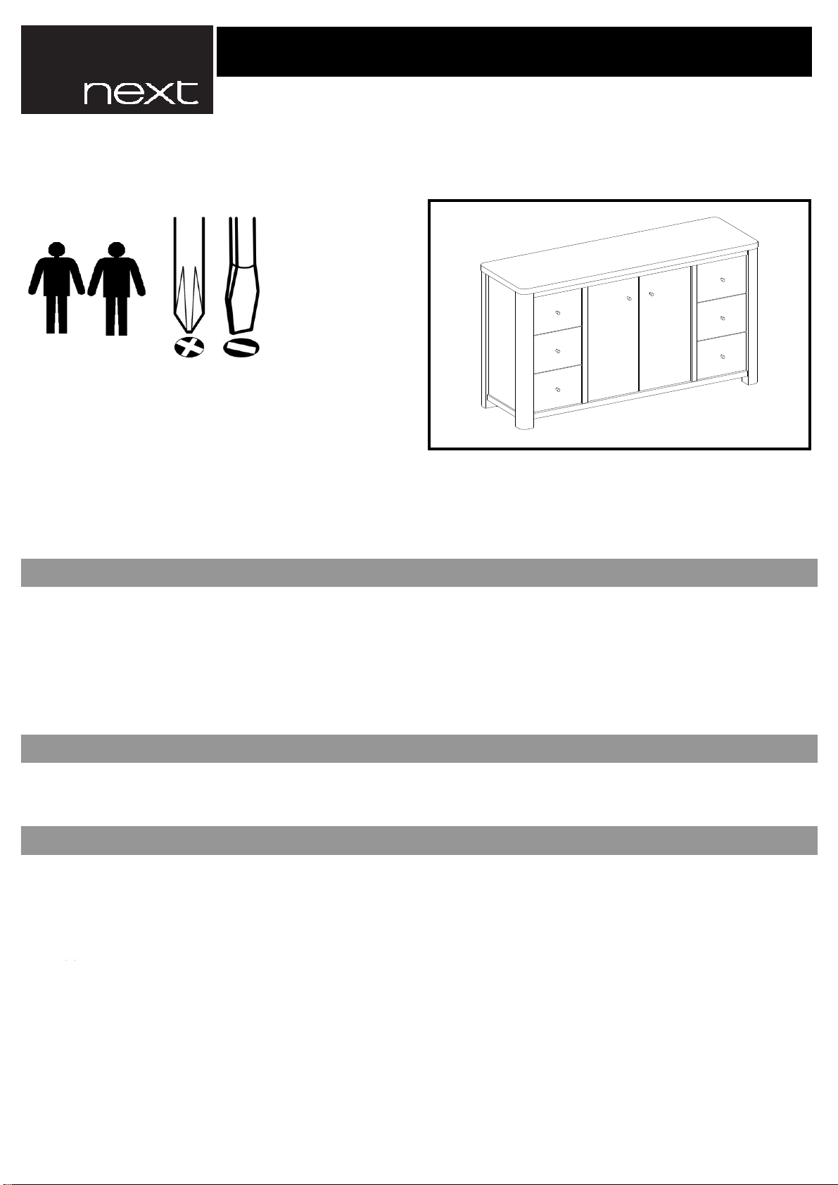
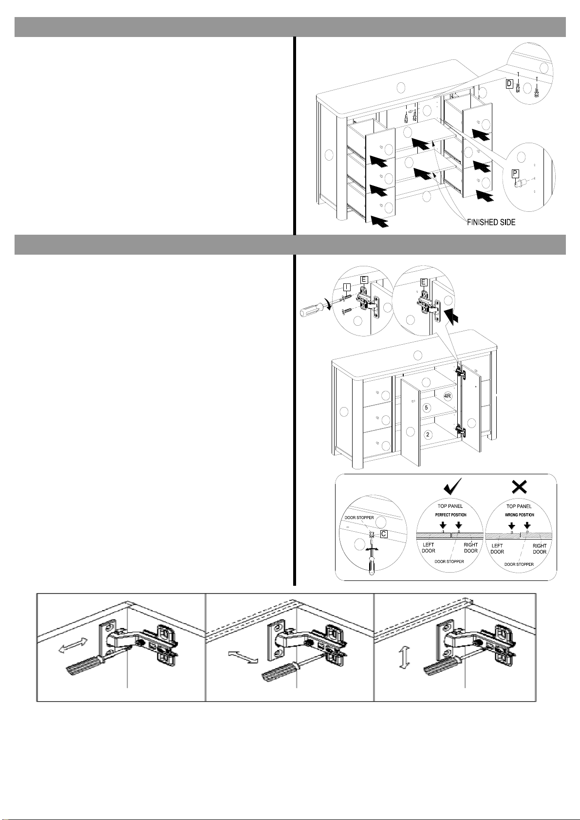
Next BARLOW SIDEBOARD 804990 User manual
Other Next Indoor Furnishing manuals

Next
Next 877740 User manual

Next
Next SLOANE 138781 User manual

Next
Next BRIGITTE T15867 User manual

Next
Next MATSON FLIP 8PX253 User manual

Next
Next BRONX 207392 User manual

Next
Next EA HARTFORD NEST S3 885156 User manual

Next
Next MALVERN DOVE 128887 User manual

Next
Next LINCOLN 876258 User manual

Next
Next home FLORENCE 848694 User manual

Next
Next BROOKSHIRE 350358 User manual

Next
Next FLYNN 565137-12 User manual

Next
Next BRONX METAL MIDI 507082 User manual

Next
Next HEX 526273 User manual

Next
Next AMELIA 895499 User manual

Next
Next CHILTERN 907026 User manual

Next
Next 543869 User manual

Next
Next FLYNN 159750 User manual

Next
Next MODE 583048 User manual

Next
Next MALVERN GREY SQUARE TO RECTANGLE DINING TABLE... User manual

Next
Next WESTCOTT 659171 User manual


Popular Indoor Furnishing manuals by other brands


Coaster
Coaster 4799N Assembly instructions

Stor-It-All
Stor-It-All WS39MP Assembly/installation instructions

Lexicon
Lexicon 194840161868 Assembly instruction

impekk
impekk Manual II Assembly And Instructions

Elements
Elements Ember Nightstand CEB700NSE Assembly instructions

JWA
JWA CARY 68429 Assembly instruction