NexxTech Professional Weather Station User manual

8001231
USER’S MANUAL

INTRODUCTION
Congratulations on your purchase of the Professional
Atomic Weather Station.
The main unit is capable of weather forecasting for the
next 12-24 hours, keeping track of the maximum and
minimum temperature, humidity, atmospheric pressure
and moon phases. No wire installation is required and
operates at 433 MHz.
In order to enjoy this weather station with its many
features, it is recommended that you read these
instructions carefully before using the weather station.
The package consists of the following:
• 1 x Radio Controlled Weather Station
• 1 x Remote Sensor
Up to three remote sensors can be utilized with the
Weather Station.

INDEX
Main Unit ...................................2-4
Remote Sensor...............................5-6
Installation of Batteries .......................... 7
Remote Sensor ............................ 7
Weather Station (Main Unit)................... 7
Low Battery Warning ........................... 8
How to Use the Table Stand or Wall Mount .......... 8
Sending and Receiving of Radio Signal ............. 9
Outdoor Temperature and Humidity ................ 9
Indoor Temperature and Humidity ................. 9
Comfort Indicator ............................. 10
Interrupted Radio Signal and Transmission . . . . . . . . . 10
Status of the Signal Transmission .................11
Maximum and Minimum Temperature and Humidity ...11
Trend Display Temperature and Humidity .......... 12
Temperature Alarm ..........................12-13
Activating the Temperature Alarm................. 13
Weather Forecast ............................. 14
Atmospheric Pressure Trend Indicator ............. 14
Moon Phase ................................. 15
Atomic Clock...............................15-18
Time, Date and Alarm Display Mode ........... 16
Manual Setting of Date, Time................. 16
Temperature Display ....................... 17
Pressure Display .......................... 17
Setting the Alarm . . . . . . . . . . . . . . . . . . . . . . . . . . 17
Turn On the Alarm ......................... 18
Snooze Alarm and Display Lighting ............ 18
View History Pressure ...................... 18
Location Setting for Sunrise and Sunset .........19-20
Precautions.................................. 20
Specications ................................ 21
FCC/RSS-210................................ 22
Warranty .................................... 23
1

MAIN UNIT
2
17
SNOOZE

MAIN UNIT
1 – 8-LINE LCD DISPLAY
Facilitates easy reading of weather forecast, indoor and
outdoor temperatures, humidity trends for temperature,
time/dual alarm, calendar, moon phase, pressure bar
chart, barometer, sunrise and sunset of 50 cities.
2 – CHANNEL BUTTON
Selects remote sensor to be displayed (for remote
sensors 2 and 3); activates or deactivates the remote
outdoor thermometer sensor reception.
3 – MAX/MIN BUTTON
Recalls the maximum and minimum temperatures as
well as maximum and minimum for indoor and remote
sensors.
4 – TIME BUTTON
For setting display variations and programming different
values.
5 – ALARM BUTTON
Display of alarm1, alarm2, or setting alarm status.
6 – SNOOZE BUTTON
Activates the snooze function.
7 – WALL MOUNT HOLE
For mounting the main unit on a wall.
8 – ALERT BUTTON
Display and programming of temperature alarm alerts.
9 – +/HR BUTTON
Advances the value of setting time, alarm, city or
switches time zone.
10 – -/RCC BUTTON
Decreases the value of setting time, alarm, city, forces
atomic time signal reception, or sets alarm on/off.
3

4
11 – LOCATION BUTTON
Sets the city sunrise and sunset.
12 – HISTORY BUTTON
Set the initial latitude, or views the pressure history of the
past 12 hours.
Advances the value of a setting.
13 – UP BUTTON
Advances the value of the setting temperature alarm,
pressure, or selects the pressure unit in mb/Hpa or inHg.
14 – DOWN BUTTON
Decreases the value of setting temperature alarm, or
pressure.
15 – BATTERY COMPARTMENT
Requires 2 x AA alkaline batteries (not included).
16 – TABLE STAND
Stands the main unit on a at surface.
17 – RESET BUTTON
Resets the settings.
MAIN UNIT
5
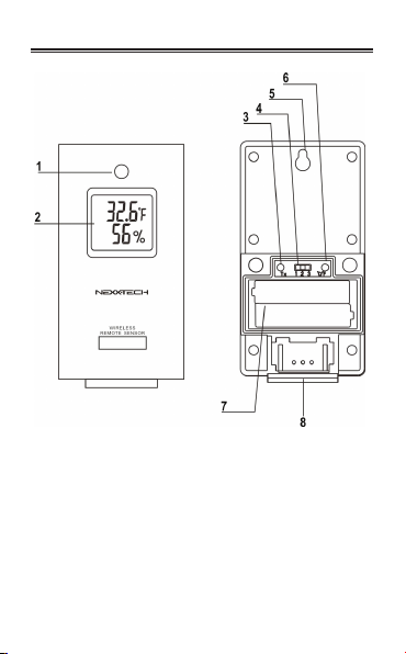
REMOTE SENSOR
5

1 – LED CONTROL LIGHT
Flashes once when the remote unit transmits a reading
upon start up or the TX button is pressed.
2 – LCD DISPLAY
LCD displays the temperature, humidity, channel
number, low battery status.
3 – TX BUTTON
Press TX button to transmit a reading, the LED ashes
once before the battery cover is closed.
4 – CHANNEL SELECTOR
Channel is to be selected before batteries are installed.
5 – WALL MOUNT HOLE
For mounting the sensor on a wall.
6 – °C/°F SWITCH
Selects between Celsius (°C) and Fahrenheit (°F)
7 – BATTERY COMPARTMENT
Requires 2 x AAA alkaline batteries
(not included).
8 – TABLE STAND
Stands the remote unit on a at surface.
REMOTE SENSOR
6

7
INSTALLATION OF BATTERIES
REMOTE SENSOR:
1. Open the battery compartment located at the back of
the sensor. Remove the 2 screws on the battery cover.
2. Select the desired channel: 1, 2 or 3.
Note: If you wish to use more than one remote sensor,
each sensor must be designated a separate channel.
3. Press the ˚C/˚F button to select between Celsius (˚C) or
Fahrenheit (˚F) setting.
4. Insert 2 x AAA alkaline batteries (not included) in the
battery compartment following the polarity markings as
shown inside the compartment.
5. Close the battery cover and reattach screws.
WEATHER STATION (MAIN UNIT):
1. Open the battery compartment located at the back of
the unit.
2. Insert 2 x AA alkaline batteries (not included) in the
battery compartment following the polarity markings as
shown inside the compartment.
3. Close the battery cover.
7

LOW BATTERY WARNING
When the battery capacity of the remote sensor is low,
a crossed battery symbol
will appear in the outdoor
temperature display of the main unit. It is time to replace
with fresh batteries.
When capacity of batteries of the main unit is low, a
crossed battery symbol
will appear in the time display
of the main unit. Please replace the low batteries with
new ones.
HOW TO USE THE
TABLE STAND OR WALL MOUNT
The main unit has a removable table stand. It may also
be mounted on the wall once the stand is removed. The
remote sensor can also stand on a table top or on the wall.
RANGE:
The maximum range of the radio signal is 20 to 30 m. It
is reduced, however, when the radio signal is interrupted
by a wall, a window or obstructions. Depending on the
material and angle involved, the range can be reduced
down to just a few meters. Different positioning of the
sensor and main unit should be tested in order to obtain
an optimal location for both units before deciding upon a
nal position.
The housing of the sensor and weather station is weather
proofed. It is recommended, however, that both units be
placed out of direct sunlight and protected against rain
and snow.
8 9

SENDING AND RECEIVING OF RADIO SIGNAL
As soon as batteries are properly inserted, the main
unit begins a three minute search for the remote sensor
signal. The units are then synchronized. The remote
sensor transmits readings with temperature and humidity
data approximately every 50~56 seconds. Reception to
the main unit is conrmed on the LCD display when the
received outdoor temperature and humidity is updated.
The main unit will automatically update its readings in
intervals of approximately 50~56 seconds. For control
purposes the LED of the remote sensor lights red during
the transmission when the TX button is pressed.
If no signals are received, blanks “—”. will appear in the
LCD display of the main unit. Press Channel button for 2
seconds to force another search whereby the main unit
and remote sensor will again be synchronized. Press
Channel button to view the outdoor temperature from the
remote sensors.
OUTDOOR TEMPERATURE AND HUMIDITY
The outdoor temperature and humidity appears on the
second line of the LCD display. If transmission from the
remote sensor to the main unit is interrupted for more than
60 minutes, “----” is displayed. When this occurs check the
remote sensor. Press Channel button on the main unit
for 2 seconds to re-synchronize the external sensor for 3
minutes again. Press Channel button to view the outdoor
temperature in the sequence of:
Sensor 1 →Sensor 2→Sensor 3 → Sensor 1-3 circular
display (
icon turns on ) →Sensor 1
INDOOR TEMPERATURE AND HUMIDITY
The indoor temperature and humidity is shown on the third
line of LCD display. Data is transferred simultaneously
from the remote sensor for both outdoor temperature and
humidity. When transmission is interrupted “—” appears in
the temperature and humidity eld of the display.
9

10
COMFORT INDICATOR
There are 3 comfort indicators: dry, wet and comfort:
1. Dry : Indoor humidity < 40%
2. Comfort : Indoor temperature: 20°C ~ 26°C (68°F ~
78.8°F), indoor humidity: 40 ~ 70%
3. Wet: Indoor humidity > 70%
INTERRUPTED RADIO SIGNAL
TRANSMISSION
If the main unit does not register signal reception from the
remote sensor “—“ will appear in the display of the main
unit. In this case. Press Channel button for 2 seconds
thereby synchronizing the main unit and the remote
sensor. If this fails and data is still not received please
check the following:
1. Whether the remote sensor is still in place.
2. Whether the batteries in the main unit and in the remote
sensor are still functioning and change if necessary.
Note: At low temperatures, especially with frost, the
voltage of the batteries in the outdoor remote sensor
can be greatly reduced. This can result in a reduced
transmission range. When outdoor temperatures are
below 0˚C (32˚F) it is recommended to use lithium
batteries in the outdoor sensor.
3. Whether the transmission is within range and path is
clear of obstacles and interference. Shorten the distance
when necessary.
4. Signals from other household devices such as computers,
TV, security systems, etc. may interfere with the radio
signals of this unit. If necessary, please relocate weather
station and sensor(s).
11

10
STATUS OF THE SIGNAL TRANSMISSION
2 possible forms of transmission can be shown on the
display of the main unit:
The unit is in searching mode
No signals
MAXIMUM AND MINIMUM
TEMPERATURE AND HUMIDITY
The Weather Station automatically stores the respective
maximum and minimum values for temperature and
humidity for indoors and outdoors.
To display these values press the MAX/MIN button:
• Press once to display the maximum values for
temperature and humidity readings stored since the last
clearing of the memory. The display will indicate: “MAX“.
• Press the MAX/MIN button a second time to display
the minimum values for temperature and humidity. The
display will indicate: “MIN“.
• Press the MEM button for 3 seconds to erase the stored
values.
• The minimum and maximum values of the selected
remote sensor (1, 2 or 3) are also displayed by pressing
the MAX/MIN button.
11
12
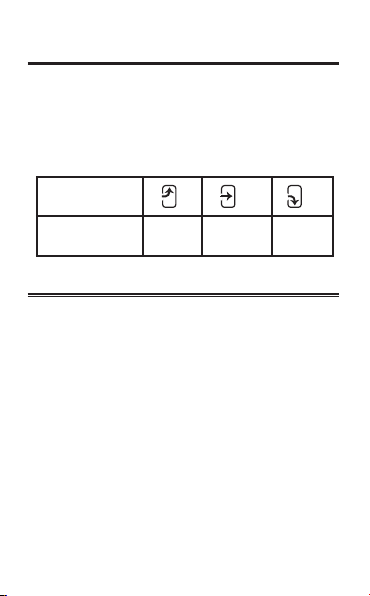
TREND DISPLAY FOR TEMPERATURE
AND HUMIDITY
The LCD display of the main unit has four trend indicators
which predict the direction in which the temperature and
humidity are changing:
• Trend arrow for indoor temperature
• Trend arrow for outdoor temperature
• Trend arrow for indoor humidity
• Trend arrow for outdoor humidity
Arrow indicator
Temperature
humidity trend Rising Steady Falling
TEMPERATURE ALARM
The Weather Station is equipped with a temperature alarm
where a customized temperature can be selected.
When the selected temperature is reached an acoustic alarm
will sound. The temperature alarm is programmed as follows:
1. Press the ALERT button to activate the temperature
alarm, the icon will display.
2. Hold the ALERT button for 2 seconds to set the upper
temperature alarm.
3. Select the desired temperature (from current
temperature to 70°C) for the upper temperature alarm
using the UP and DOWN buttons.
4. Press ALERT button to conrm the upper temperature
alarm and to set the lower temperature alarm.
5. Select the desired temperature (from -40°C to the
current temperature) for the lower temperature alarm
using the UP and DOWN buttons.
6. Press ALERT button to conrm.

TEMPERATURE ALARM
Temperature
alert indicator
Temperature
alarm status
Temperature
alarm OFF
Temperature
alarm ON
Setting upper
temperature
alarm
Setting lower
temperature
alarm
ACTIVATING THE TEMPERATURE ALARM
When the temperature alarm turns on, an acoustic alarm
will be initiated (with 3 continuous alarm sounds, 4 beeps
each time) every minute if the temperature of the channel
displayed reaches the preset alert temperature.
The temperature alarm stops when the temperature no
longer meets the customized temperature setting or when
the ALERT button is pressed to disable the temperature
alarm function.
13
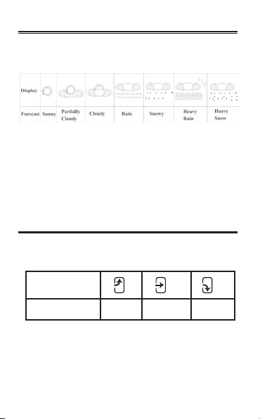
WEATHER FORECAST
This unit is capable of detecting atmospheric pressure
changes. Based on collected date it can predict the
weather for the upcoming 12 to 24 hours.
Note:
• The accuracy of a general pressure-based weather
forecast is 70%.
• The weather forecast indicates the forthcoming change
and not necessarily the current weather situation.
• The symbol “Sunny” applies also to night time.
It indicates clear skies/without clouds.
ATMOSPHERIC PRESSURE TREND INDICATOR
The atmospheric pressure indicator in the weather forecast
window of the main unit uses arrows to indicate trend changes
in atmospheric pressure and therefore weather changes:
Arrow indicator
Pressure trend Rising Steady Falling
• Rising pressure = the weather is changing for the better
(fair weather)
• Falling pressure = the weather is changing for the worse
(inclement weather)
14
ATOMIC CLOCK
The weather station is equipped with an atomic clock. It
functions with utmost precision. The transition from normal
time to day light savings time is automatic.
• Once the batteries are inserted the clock will automatically
search for the radio signal after it synchronizes with the
outdoor sensor(s). This process is completed within
approximately 3 to 7 minutes.
• As soon as the radio signal has been received the time will
be displayed (hour, minutes and seconds). The symbol
will appear in the display as conrmation of a successful
radio signal reception.
• If the search for the radio signal is not successful the
symbol will not appear. Instead the symbol for signal search
will be displayed. The time may need to be set manually.
• If the radio signal is not received, press the -/RCC button for
2 seconds to initiate a search for the radio signal.
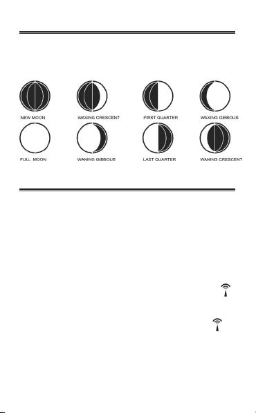
MOON PHASE
The weather station is equipped with a moon phase display
which indicates eight moon phases from new moon to waning
crescent.
15

16
• During radio reception, press the -/RCC button will stop the
radio reception.
• The atomic clock will automatically receive the WWVB time
code during the middle of the night. The signal is automatically
sent at intervals at 2:03 am, 3:03 am and 4:03 am.
Note: The radio controlled signal for time (WWVB 60 KHz) is
transmitted from the WWVB radio station derives its signal
from the NIST Atomic clock in Boulder, Colorado.
It has a reception range of approximately 3,218 kms (2000
miles). Obstructions such as concrete walls can reduce the
signal range.
TIME, DATE AND ALARM DISPLAY MODE
The main unit receives and displays together with the time and the
date. Press MODE for the following:
• Press TIME to change the display between the calendar
year or calendar day of week.
• Press ALARM button to switch between time, alarm1 or
alarm2.
• Press the +/HR button to switch among the time zone in the
sequence as the following:
Pacic Time (P) → Mountain Time (M)→ Central Time (C)→
Eastern Time (E)→ P.
MANUAL SETTING OF DATE, TIME
Press TIME button for 2 seconds the setting values to be
changed begins to ash. Use the + button to increase and the
- button to decrease the value. If the values are not numerical
the + and - button will offer other possibilities. The sequence of
the values to be set are the following:
1. Calendar Year
2. Sequence of Date (Month/Day or Day/Month) Display
3. Month
4. Day

17
5. Languages (7), English (EN), German (GE), Italian (IT), French
(FR), Dutch (NE), Spanish (ES), Danish (DA)
6. Hour Format 12 or 24 hour
7. Hour
8. Minutes
9. DST On or Off
Note:
1. When the minute value is edited; the seconds value is
reset to 00.
2. If no buttons are pressed within 8 seconds, it will exit the
manual time set mode.
TEMPERATURE DISPLAY
Press DOWN to toggle the temperature display between
Celsius and Fahrenheit
PRESSURE DISPLAY
Press UP to toggle the pressure display between mb/Hpa
and inHg.
SETTING THE ALARM
Press ALARM button to view the current time, alarm1 time or
alarm2. In alarm1 display, press ALARM button for 2 seconds
until the alarm1 hour ashes. Press + or - to increase or
decrease the alarm hour. Press ALARM to conrm the
alarm1 hour. The alarm1 minute display ash. Press + or - to
increease or decrease the alarm minute. Press ALARM to
conrm the alarm1 time setting.
For alarm2 setting, press ALARM button until alarm2 is
display. Repeat the above alarm setting procedure.
Note: If no buttons are pressed within 8 seconds, it will exit
the alarm time set mode.

18
TURN ON THE ALARM
Press the -/RCC button, it will turn the alarm on/off in the
following sequence:
Alarm1 on
→ Alarm2 on
→ Alarm1 & Alarm2 on
→ Alarm1 & Alarm2 off→ Alarm1 on
SNOOZE ALARM AND DISPLAY LIGHTING
The SNOOZE button is on the front side of the weather
station. When the time reaches the corresponding alarm
time, the alarm is activated for maximum 2 minutes and the
alarm icon (
or
) ashes. Press snooze to stop the
alarm and the backlight will turn on for 5 seconds and the
corresponding alarm icon and the “Zz” icon will ash for 5
minutes. After 5 minutes the alarm will activate again. When
the alarm is sounding, press any button except the snooze
button to stop the alarm.
During the snooze period, press any button except the
snooze button to stop the snooze function.
VIEW PRESSURE HISTORY
Press the HISTORY button to view the past 12 hours’ pressure
history in the sequence of (0, -1, -2, ..., -9, -10, -11, -12, 0).
19
Table of contents
Other NexxTech Weather Station manuals


