2
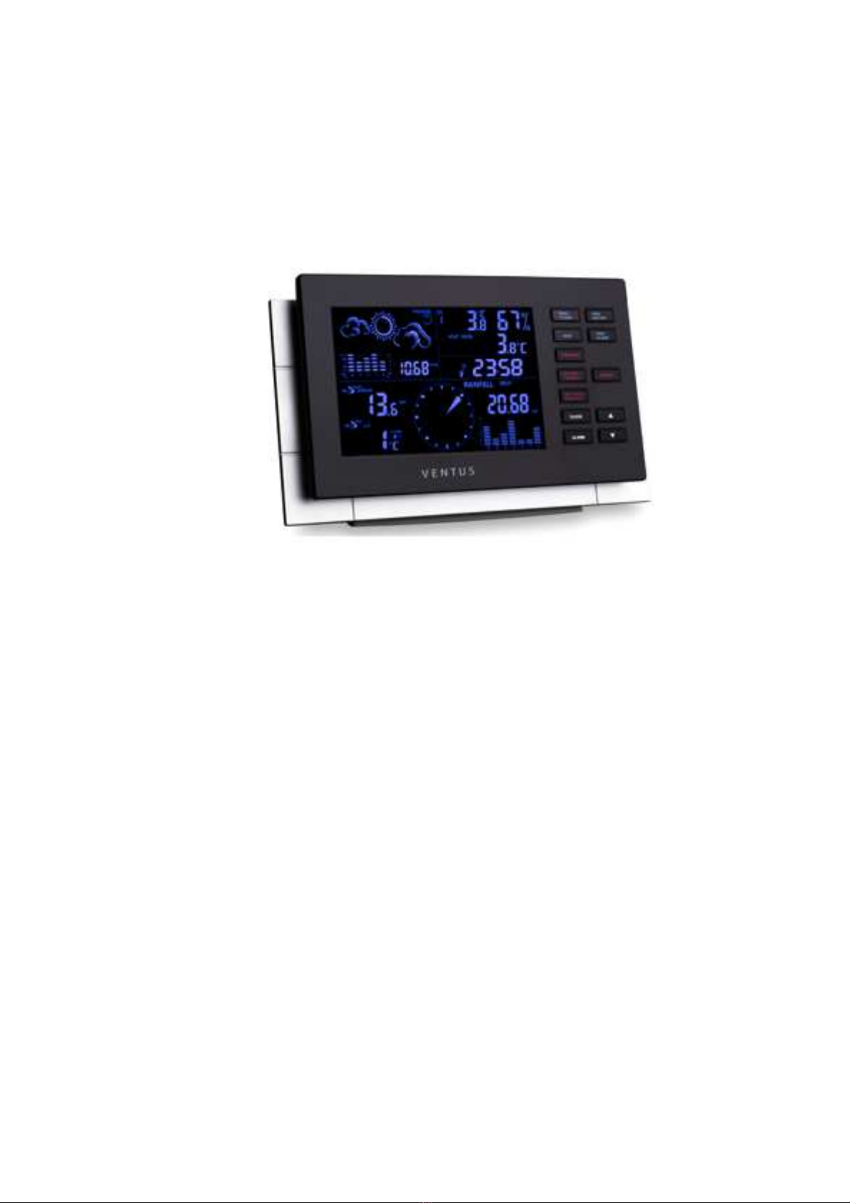
Sea level pressure setting
After battery/adapter installation, the monitor will enter sea level pressure setting mode directly and the
pressure reading will flash. Press “▲” or “▼” to set the sea level pressure value. Press “PRESSURE” to
confirm the setting and exit. This allows the unit to provide a more accurate weather forecast &
pressure reading.
You can also set the sea level pressure any time after the installation is completed. For more
information, see “WEATHER FORECAST & BAROMETRIC PRESSURE” section.
Note: you may obtain the current sea level pressure from the weather web site for your locate area.
2. Selecting a location for the anemometer
Select a mounting location for the anemometer that is:
-Outdoors, not blocked on top or sides, so wind can freely reach the anemometer
-Within 30 meter open area from the monitor. Reduce distance if obstacles is between the
anemometer & the monitor
The best location for the anemometer is usually mounted on a mast in an open area where wind is not
blocked on top or sides, or above roof level on the building where the monitor is located.
Testing the effective transmission range
Before mounting the anemometer, measure the distance between the monitor & anemometer and be
sure it is within the effective transmission range. It is recommended to perform a simple RF
transmission test before mounting.
1) Place the monitor in your selected indoor location and install adapter & batteries (see “Battery &
adapter installation for the monitor” section above)
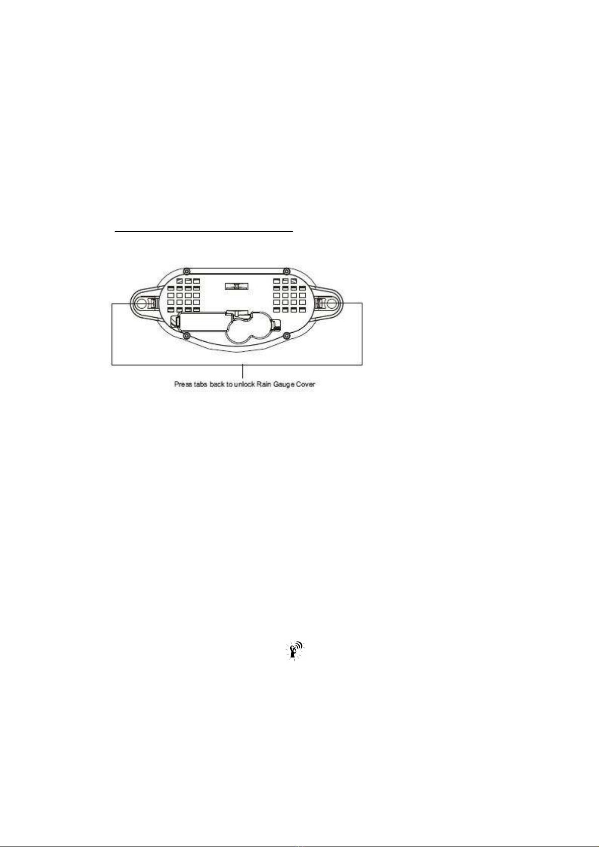
2) Place the anemometer horizontally in your selected outdoor location. Loosen the screws on the
battery door with a small Phillips screwdriver and open the battery door. Insert 2 pieces of AA
batteries according to the polarity indicated. Close the battery door and tighten the screws.
3) Hold “CHANNEL/SEARCH” button on the monitor for 3 seconds and the wind direction,
temperature & humidity icons will flash on the display. The monitor is now searching for all remote
sensors for 2 minutes.
4) If valid wind direction, wind speed and channel-1 temperature/humidity readings are shown on the
monitor within 2 minutes, the RF transmission is successful and the anemometer & monitor are
within the effective transmission.
If above readings are not shown after 2 minutes of searching, the transmission is failed.
Shorten the distance between the anemometer & monitor. Reset the anemometer by removing all
batteries from the anemometer & wait for 10 seconds before re-installing the batteries again.
Repeat step 3 & 4 until the transmission is successful.
5) Remove all batteries from the anemometer before mounting and calibration.