NI PXIe-4138 User manual

GETTING STARTED GUIDE
NI PXIe-4138/4139
PXIe, ±60 V, ±3 A (DC)/±10 A (Pulsed) Precision System PXI Source
Measure Unit
This document explains how to install, configure, and test the PXIe-4138/4139. The
PXIe-4138/4139 ships with NI-DCPower driver software, which you can use to program the
module.
Note Before you begin, install and configure your chassis and controller.
Note In this document, the PXIe-4139 (40W) and PXIe-4139 (20W) are referred to
inclusively as the PXIe-4139. The information in this document applies to all
versions of the PXIe-4139 unless otherwise specified. To determine which version of
the module you have, locate the device name in one of the following places:
•In MAX—The PXIe-4139 (40W) shows NI PXIe-4139 (40W), and the
PXIe-4139 (20W) shows as NI PXIe-4139.
•Device front panel—The PXIe-4139 (40W) shows PXIe-4139 40W System
SMU, and the PXIe-4139 (20W) shows NI PXIe-4139 Precision System SMU
on the front panel.
Contents
Verifying the System Requirements..........................................................................................2
Unpacking the Kit..................................................................................................................... 2
Kit Contents.............................................................................................................................. 2
Other Equipment....................................................................................................................... 3
Preparing the Environment....................................................................................................... 3
Installing the Software.............................................................................................................. 3
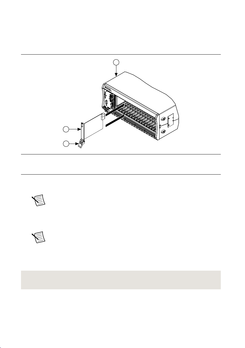
Installing the PXIe-4138/4139.................................................................................................. 4
PXIe-4138 Pinout .....................................................................................................................6
PXIe-4139 Pinout .....................................................................................................................8
Configuring the PXIe-4138/4139 in MAX............................................................................... 9
Self-Calibrating the PXIe-4138/4139..................................................................................... 10
Programming the PXIe-4138/4139......................................................................................... 11
Troubleshooting...................................................................................................................... 13
What Should I Do if the PXIe-4138/4139 Doesn't Appear in MAX?............................ 13
Why Is the ACCESS LED Off When the Chassis Is On?...............................................14
What Should I Do if the PXIe-4138/4139 Fails the Self-Test?.......................................14
Where To Go Next.................................................................................................................. 15
NI Services..............................................................................................................................15

Verifying the System Requirements
To use the NI-DCPower instrument driver, your system must meet certain requirements.
Refer to the product readme, which is available on the driver software media or online at
ni.com/manuals, for more information about minimum system requirements, recommended
system, and supported application development environments (ADEs).
Unpacking the Kit
Notice To prevent electrostatic discharge (ESD) from damaging the module,
ground yourself using a grounding strap or by holding a grounded object, such as
your computer chassis.
1. Touch the antistatic package to a metal part of the computer chassis.
2. Remove the module from the package and inspect it for loose components or other signs
of damage.
Notice Never touch the exposed pins of connectors.
Note Do not install a module if it appears damaged in any way.
3. Unpack any other items and documentation from the kit.
Store the module in the antistatic package when the module is not in use.
Kit Contents
Figure 1. NI 4138/4139 Kit Contents
3
12
OUTPUTCAT I
ACCESS ACTIVE
LO
NSE
LO
ARD
HI
ARD
NSE
HI
SystemSMU
NI PXIe-4138
OUTPUT
±60V , 3 A MAX
150V MAXto
4
1. NI PXIe-4138/4139 System SMU Device
2. Output Connector Assembly
3. Safety, Environmental, and Regulatory
Information
4. Product documentation
2| ni.com | NI PXIe-4138/4139 Getting Started Guide

Other Equipment
There are several required items not included in your PXIe-4138/4139 kit that you need to
operate the PXIe-4138/4139. Your application may require additional items not included in
your kit to install or operate your PXIe-4138/4139.
Required Items
• A PXI Express chassis and chassis documentation. For more information about
compatible chassis options, refer to ni.com.
• A PXI Express embedded controller or MXI controller system that meets the system
requirements specified in this guide and chassis documentation.
Optional Items
• PXI Slot Blocker Kit (NI part number 199198-01)
• NI screwdriver (NI part number 781015-01)
Visit ni.com for more information about these additional items.
Preparing the Environment
Ensure that the environment you are using the PXIe-4138/4139 in meets the following
specifications:
Temperature and Humidity
Temperature
Operating 0 °C to 55 °C
Storage -40 °C to 70 °C
Humidity
Operating 10% to 90%, noncondensing
Storage 5% to 95%, noncondensing
Pollution Degree 2
Maximum altitude 2,000 m (800 mbar) (at 25 °C ambient
temperature)
Notice This model is intended for use in indoor applications only.
Installing the Software
You must be an Administrator to install NI software on your computer.
1. Install an ADE, such as LabVIEW or LabWindows™/CVI™.
NI PXIe-4138/4139 Getting Started Guide | © National Instruments Corporation | 3

2. Download the driver software installer from ni.com/downloads or install the driver
software from the physical media included with your product.
NI Package Manager downloads with the driver software to handle the installation. Refer
to the NI Package Manager Manual for more information about installing, removing, and
upgrading NI software using NI Package Manager.
3. Follow the instructions in the installation prompts.
Note Windows users may see access and security messages during
installation. Accept the prompts to complete the installation.
4. When the installer completes, select Restart in the dialog box that prompts you to restart,
shut down, or restart later.
Installing the PXIe-4138/4139
Notice To prevent damage to the PXIe-4138/4139 caused by ESD or
contamination, handle the module using the edges or the metal bracket.
1. Ensure the AC power source is connected to the chassis before installing the
PXIe-4138/4139.
The AC power cord grounds the chassis and protects it from electrical damage while you
install the PXIe-4138/4139.
2. Power off the chassis.
3. Inspect the slot pins on the chassis backplane for any bends or damage prior to
installation. Do not install a module if the backplane is damaged.
4. Position the chassis so that inlet and outlet vents are not obstructed.
For more information about optimal chassis positioning, refer to the chassis
documentation.
5. Remove the black plastic covers from all the captive screws on the module front panel.
6. Identify a supported slot in the chassis. The following figure shows the symbols that
indicate the slot types.
Figure 2. Chassis Compatibility Symbols
NI PXIe-1062Q
12 3 45
1. PXI Express System Controller Slot
2. PXI Peripheral Slot
3. PXI Express Hybrid Peripheral Slot
4. PXI Express System Timing Slot
5. PXI Express Peripheral Slot
PXIe-4138/4139 modules can be placed in PXI Express peripheral slots, PXI Express
hybrid peripheral slots, or PXI Express system timing slots.
4| ni.com | NI PXIe-4138/4139 Getting Started Guide

7. Touch any metal part of the chassis to discharge static electricity.
8. Ensure that the ejector handle is in the downward (unlatched) position.
9. Place the module edges into the module guides at the top and bottom of the chassis. Slide
the module into the slot until it is fully inserted.
Figure 3. Module Installation
2
3
NI PXIe-1075
1
1. Chassis
2. Hardware Module
3. Ejector Handle in Downward (Unlatched) Position
10. Latch the module in place by pulling up on the ejector handle.
11. Secure the module front panel to the chassis using the front-panel mounting screws.
Note Tightening the top and bottom mounting screws increases mechanical
stability and also electrically connects the front panel to the chassis, which can
improve the signal quality and electromagnetic performance.
12. Cover all empty slots using either filler panels (standard or EMC) or slot blockers with
filler panels, depending on your application.
Note For more information about installing slot blockers and filler panels, go
to ni.com/r/pxiblocker.
13. Connect the output connector assembly to the device. Tighten any thumbscrews on the
output connector assembly to hold it in place.
14. Power on the chassis.
Related Information
Why Is the ACCESS LED Off When the Chassis Is On? on page 14
NI PXIe-4138/4139 Getting Started Guide | © National Instruments Corporation | 5

PXIe-4138 Pinout
NI PXIe-4138
System SMU
±60 V , 3 A MAX
150 V MAX to
LO
SENSE
LO
SENSE
HI
HI
GUARD
GUARD
ACCESS ACTIVE
OUTPUT
OUTPUT CAT I
C
D
E
F
G
H
I
J
A
B
K
Table 1. Signal Descriptions
Item Description
A Access Status LED
B Active Status LED
C Output LO
D Sense LO
E Guard
F Output HI
6| ni.com | NI PXIe-4138/4139 Getting Started Guide

Table 1. Signal Descriptions (Continued)
Item Description
G Guard
H Guard
I Guard
J Sense HI
K Chassis Ground
Table 2. LED Access Status Indicator
Status Indicator Device State
(Off) Not Powered
Green Powered
Amber Device is being accessed
Table 3. LED Active Status Indicator
Status Indicator Output Channel State
(Off) Channel not operating in a programmed state
Green Channel operating in a programmed state
Red Channel disabled because of error, such as an overcurrent condition
NI PXIe-4138/4139 Getting Started Guide | © National Instruments Corporation | 7

PXIe-4139 Pinout
NI PXIe-4139
Precision System SMU
60 V , 3 A, 10 A Pulse MAX
150 V MAX to
LO
SENSE
LO
SENSE
HI
HI
GUARD
GUARD
ACCESS ACTIVE
OUTPUT
OUTPUT CAT I
C
D
E
F
G
H
I
J
K
A
B
PXIe-4139
40W System SMU
60 V , 3 A, 10 A Pulse MAX
150 V MAX to
LO
SENSE
LO
SENSE
HI
HI
GUARD
GUARD
ACCESS ACTIVE
OUTPUT
OUTPUT CAT I
K
A
B
Table 4. Signal Descriptions
Item Description
A Access Status LED
B Active Status LED
C Output LO
8| ni.com | NI PXIe-4138/4139 Getting Started Guide

Table 4. Signal Descriptions (Continued)
Item Description
D Sense LO
E Guard
F Output HI
G Guard
H Guard
I Guard
J Sense HI
K Chassis Ground
Table 5. LED Access Status Indicator
Status Indicator Device State
(Off) Not Powered
Green Powered
Amber Device is being accessed
Table 6. LED Active Status Indicator
Status Indicator Output Channel State
(Off) Channel not operating in a programmed state
Green Channel operating in a programmed state
Red Channel disabled because of error, such as an overcurrent condition
Configuring the PXIe-4138/4139 in MAX
Use Measurement & Automation Explorer (MAX) to configure your NI hardware. MAX
informs other programs about which NI hardware products are in the system and how they are
configured. MAX is automatically installed with NI-DCPower.
1. Launch MAX.
2. In the configuration tree, expand Devices and Interfaces to see the list of installed NI
hardware.
Installed modules appear under the name of their associated chassis.
NI PXIe-4138/4139 Getting Started Guide | © National Instruments Corporation | 9

3. Expand your Chassis tree item.
MAX lists all modules installed in the chassis. Your default names may vary.
Note If you do not see your module listed, press <F5> to refresh the list of
installed modules. If the module is still not listed, power off the system, ensure
the module is correctly installed, and restart.
4. Record the identifier MAX assigns to the hardware. Use this identifier when
programming the PXIe-4138/4139.
5. Self-test the hardware by selecting the item in the configuration tree and clicking Self-
Test in the MAX toolbar.
The MAX self-test performs a basic verification of hardware resources.
Related Information
What Should I Do if the PXIe-4138/4139 Doesn't Appear in MAX? on page 13
Self-Calibrating the PXIe-4138/4139
Self-calibration adjusts the PXIe-4138/4139 for variations in the module environment.
Perform a complete self-calibration after the first time you install the PXIe-4138/4139.
1. Install the PXIe-4138/4139 and let it warm up for 30 minutes.
Note Warm up begins when the PXI Express chassis has been powered on and
the operating system has completely loaded.
2. Self-calibrate the PXIe-4138/4139 by clicking the Self-Calibrate button in MAX or
calling niDCPower Cal Self Calibrate or niDCPower_CalSelfCalibrate.
The PXIe-4138/4139 modules are externally calibrated at the factory but you should perform a
self-calibration in all of the following situations:
• After first installing the PXIe-4138/4139 in a chassis
• After any module that is in the same chassis as the PXIe-4138/4139 is installed,
uninstalled, or moved
• When the PXIe-4138/4139 is in an environment where the ambient temperature varies or
the PXIe-4138/4139 temperature has drifted more than ±5 °C from the temperature at the
last self-calibration
• Within 24 hours of the previous self-calibration
Related Information
What Should I Do if the PXIe-4138/4139 Fails the Self-Test? on page 14
10 | ni.com | NI PXIe-4138/4139 Getting Started Guide

Programming the PXIe-4138/4139
You can generate signals interactively using InstrumentStudio or you can use the NI-DCPower
instrument driver to program your device in the supported ADE of your choice.
NI PXIe-4138/4139 Getting Started Guide | © National Instruments Corporation | 11

Software Location Description
InstrumentStudio InstrumentStudio is automatically installed
when you install the NI-DCPower driver on
a 64-bit system. You can access
InstrumentStudio in any of the following
ways:
• From the Windows start menu, select
National Instruments»[Driver] Soft
Front Panel. This launches
InstrumentStudio and runs a soft front
panel populated with NI-DCPower
devices.
• From the Windows start menu, select
National Instruments»
InstrumentStudio [year]. This
launches InstrumentStudio and runs a
soft front panel populated with devices
detected on your system.
• From Measurement & Automation
Explorer (MAX), select a device and
then click Test Panels.... This launches
InstrumentStudio and runs a soft front
panel for the device you selected.
When you install NI-
DCPower on a 64-bit
system, you can monitor,
control, and record
measurements from
supported devices using
InstrumentStudio.
InstrumentStudio is a
software-based soft front
panel application that
allows you to perform
interactive measurements
on several different
device types in a single
program.
12 | ni.com | NI PXIe-4138/4139 Getting Started Guide

Software Location Description
NI-DCPower
Instrument Driver
LabVIEW—Available on the LabVIEW
Functions palette at Measurement I/O »
NI-DCPower . Examples are available from
the Start menu in the National
Instruments folder.
The NI-DCPower API
configures and operates
the module hardware and
performs basic acquisition
and measurement
functions.
LabVIEW NXG—Available from the
diagram at Hardware Interfaces »
Electronic Test »NI-DCPower . Examples
are available from the Learning tab in the
Examples »Hardware Input and Output
folder.
LabWindows/CVI—Available at Program
Files »IVI Foundation »IVI »Drivers »
NI-DCPower . LabWindows/CVI examples
are available from the Start menu in the
National Instruments folder.
C/C++—Available at Program Files »IVI
Foundation »IVI . Refer to the Creating an
Application with NI-DCPower in Microsoft
Visual C and C++ topic of the NI DC
Power Supplies and SMUs Help (installed
with the NI-DCPower driver software) to
manually add all required include and
library files to your project. NI-DCPower
does not ship with installed C/C++
examples.
Troubleshooting
If an issue persists after you complete a troubleshooting procedure, contact NI technical
support or visit ni.com/support.
What Should I Do if the PXIe-4138/4139 Doesn't
Appear in MAX?
1. In the MAX configuration tree, expand Devices and Interfaces.
2. Expand the Chassis tree to see the list of installed hardware, and press <F5> to refresh
the list.
3. If the module is still not listed, power off the system, ensure that all hardware is correctly
installed, and restart the system.
4. Navigate to the Device Manager.
NI PXIe-4138/4139 Getting Started Guide | © National Instruments Corporation | 13

Operating System Description
Windows 10/8.1 Right-click the Start button, and select Device Manager.
Windows 7 Select Start»Control Panel»Device Manager.
5. Verify the PXIe-4138/4139 appears in the Device Manager.
a) Under an NI entry, confirm that a PXIe-4138/4139 entry appears.
Note If you are using a PC with a device for PXI remote control system,
under System Devices, also confirm that no error conditions appear for the
PCI-to-PCI Bridge.
b) If error conditions appear, reinstall NI-DCPower and the PXIe-4138/4139.
Why Is the ACCESS LED Off When the Chassis Is
On?
Before proceeding, verify that the PXIe-4138/4139 appears in MAX.
If the ACCESS LED fails to light after you power on the chassis, a problem may exist with the
chassis power rails, a hardware module, or the LED.
Notice Apply external signals only while the PXIe-4138/4139 is powered on.
Applying external signals while the module is powered off may cause damage.
1. Disconnect any signals from the module front panels.
2. Power off the chassis.
3. Remove the module from the chassis and inspect it for damage. Do not reinstall a
damaged module.
4. Install the module in a different chassis slot from which you removed it.
5. Power on the chassis.
Note If you are using a PC with a device for PXI remote control system,
power on the chassis before powering on the computer.
6. Verify that the module appears in MAX.
7. Reset the module in MAX and perform a self-test.
What Should I Do if the PXIe-4138/4139 Fails the Self-
Test?
1. Restart the system.
2. Launch MAX.
• Failed self-test
1. Perform self-calibration, then perform the self-test again. The PXIe-4138/4139
must be calibrated to pass the self-test.
• Failed self-calibration
1. Perform self-calibration again.
3. Power off the chassis.
14 | ni.com | NI PXIe-4138/4139 Getting Started Guide

4. Reinstall the failed module in a different slot.
5. Power on the chassis.
6. Perform the self-test again.
Where To Go Next
custom applications with
an application programming
interface (API).
NI-DCPower Soft Front Panel
NI-DCPower Instrument Driver
about hardware features
or review device
specifications.
more about your products through ni.com.
NI PXIe 4138 Specifications*
OR
NI PXIe 4139 Specifications*
NI DC Power Supplies
and SMUs Help*
the application
development environment (ADE)
for your application.
*This item is also installed with the driver software.
Located online at ni.com/manuals Located using the NI Example Finder
EXPLORE LEARN CREATE
DISCOVER
Support
ni.com/support
Power Supplies
Solutions
ni.com/powersupplies
Services
ni.com/services
NI Community
ni.com/community
NIPXIe-4138
Getting Started with
LabWindows/CVI
Getting Started with
LabVIEW
NI DCPower Examples*
NI DC Power Supplies
and SMUs Help*
NI Services
Visit ni.com/support to find support resources including documentation, downloads, and
troubleshooting and application development self-help such as tutorials and examples.
Visit ni.com/services to learn about NI service offerings such as calibration options, repair, and
replacement.
Visit ni.com/register to register your NI product. Product registration facilitates technical
support and ensures that you receive important information updates from NI.
NI corporate headquarters is located at 11500 N Mopac Expwy, Austin, TX, 78759-3504,
USA.
NI PXIe-4138/4139 Getting Started Guide | © National Instruments Corporation | 15

Information is subject to change without notice. Refer to the NI Trademarks and Logo Guidelines at ni.com/trademarks for
information on NI trademarks. Other product and company names mentioned herein are trademarks or trade names of their
respective companies. For patents covering NI products/technology, refer to the appropriate location: Help»Patents in your
software, the patents.txt file on your media, or the National Instruments Patent Notice at ni.com/patents. You can find
information about end-user license agreements (EULAs) and third-party legal notices in the readme file for your NI product. Refer
to the Export Compliance Information at ni.com/legal/export-compliance for the NI global trade compliance policy and how
to obtain relevant HTS codes, ECCNs, and other import/export data. NI MAKES NO EXPRESS OR IMPLIED WARRANTIES AS
TO THE ACCURACY OF THE INFORMATION CONTAINED HEREIN AND SHALL NOT BE LIABLE FOR ANY ERRORS. U.S.
Government Customers: The data contained in this manual was developed at private expense and is subject to the applicable
limited rights and restricted data rights as set forth in FAR 52.227-14, DFAR 252.227-7014, and DFAR 252.227-7015.
© 2014—2020 National Instruments Corporation. All rights reserved.
374671C-01 November 27, 2020
This manual suits for next models
1
Table of contents
Other NI Measuring Instrument manuals
Popular Measuring Instrument manuals by other brands

Hach
Hach H120 operating instructions

CORNING
CORNING Lambda Plus instruction manual

SMA
SMA SCHOOLMETERBOX installation guide

BW SENSING
BW SENSING BWM466 Series Technical manual

Tektronix
Tektronix OI tek P5200A Series Installation and safety instructions

RKI Instruments
RKI Instruments GX-3R Operator's manual

Camax
Camax Powercom3 user manual

VibrAlign
VibrAlign Fixturlaser Laser Kit Quick tips

DH Instruments
DH Instruments PG7607 - 2006 Operation and maintenance manual

INTEGRA Merering
INTEGRA Merering Calec energy master Installation and operating instructions

Ares
Ares 10020 Operation manual

Rigaku
Rigaku XtaLAB mini instruction manual