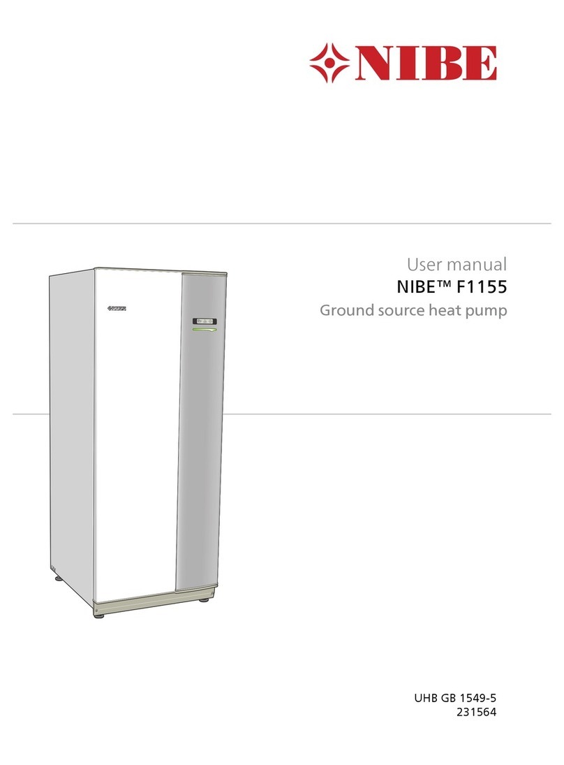
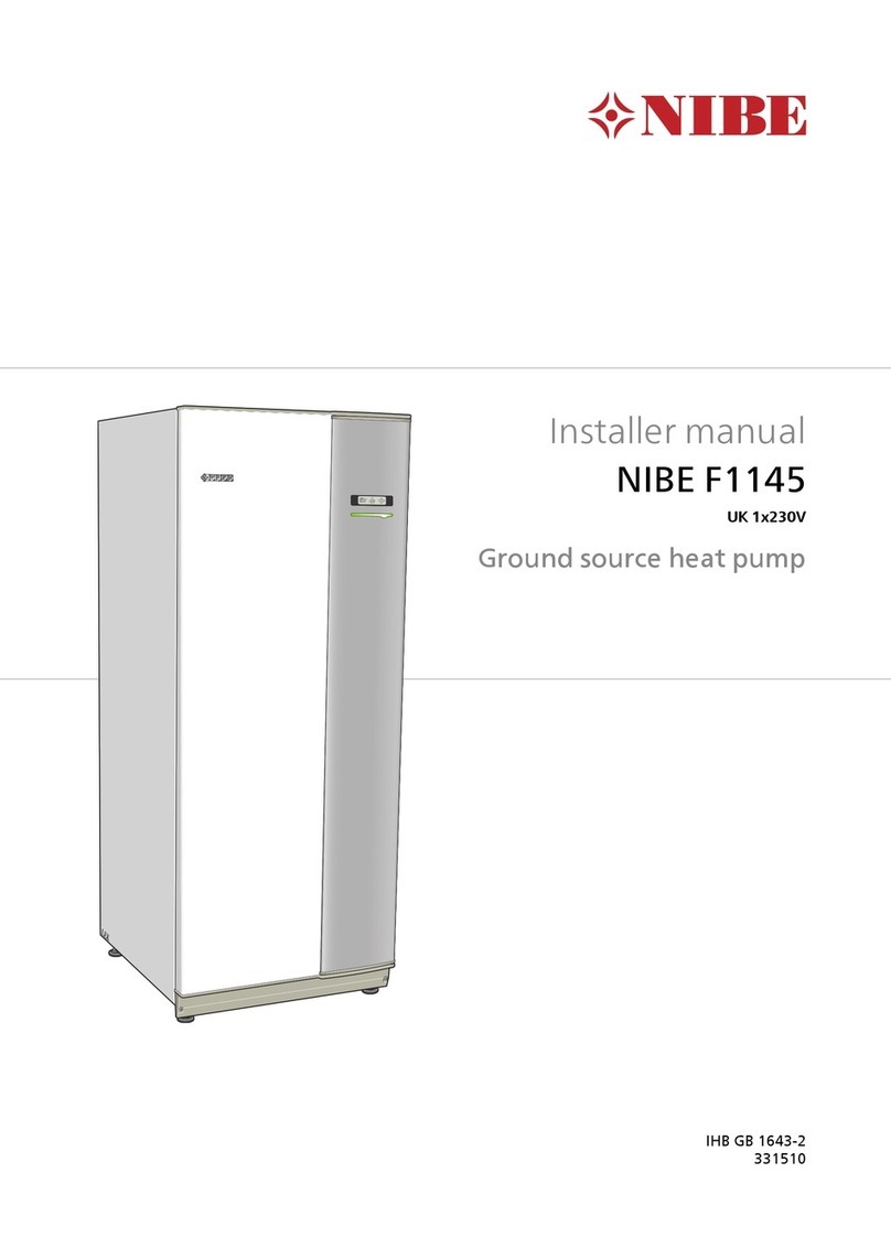
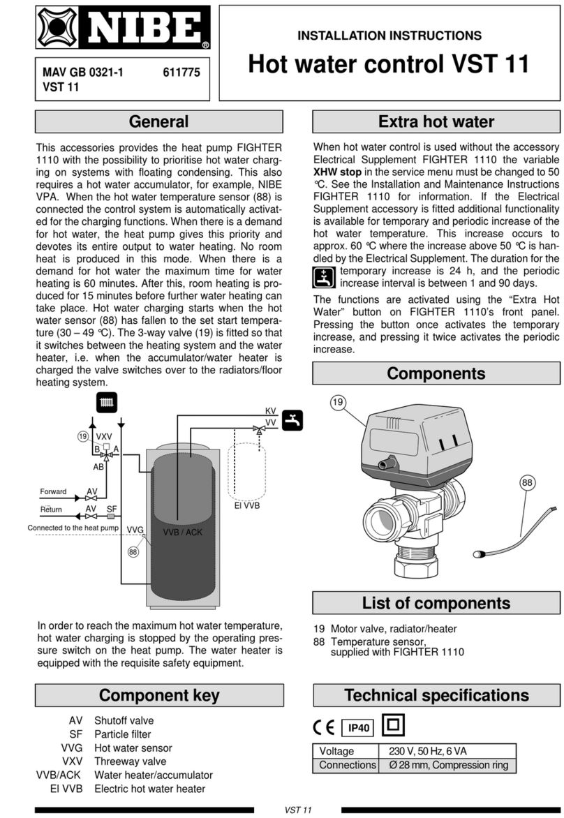
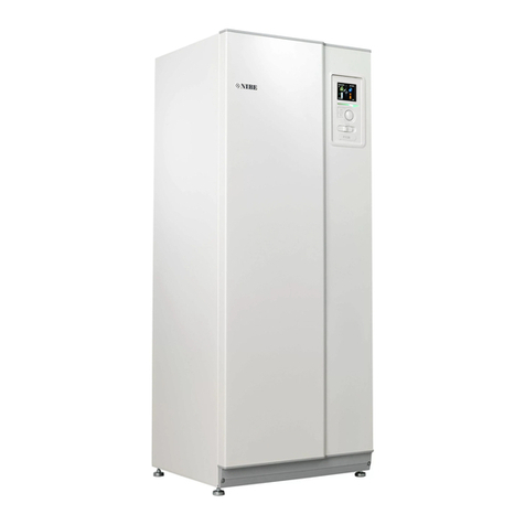
Nibe Fighter 1210 User manual

R
INSTALLATION AND MAINTENANCE INSTRUCTIONS
FIGHTER 1210
MOS GB 0428-1 411195
FIGHTER 1210
LEK
Fighter 1215


For the Installer
Contents 1
FIGHTER 1210
For Home Owners
General information for the installer
Transport and storage ..........................................10
Installation ............................................................10
Guideline values for collectors ..............................10
Inspection of the installation ..................................10
Electric boiler mode .............................................. 10
brine pump............................................................ 10
Control
General ................................................................ 11
Settings ................................................................ 11
Pipe connections
General ................................................................ 14
Pipe connection (collector) .................................. 14
Pipe connection (heating medium) ...................... 14
Pipe connections (water heater) .......................... 14
Tap water connection .......................................... 15
Ventilation recovery .............................................. 15
Free cooling ........................................................ 15
Pump capacity diagrams, heating medium side .. 16
Electrical connections
Connection .......................................................... 17
External control of the immersion heater .............. 18
Power rating as set at the factory ........................ 18
Connecting the outside sensor.............................. 18
Commissioning and adjusting
Preparations ........................................................ 19
Filling and venting the
collector
system .............. 19
Filling the heating/heating medium systems ........ 19
Starting and checking .......................................... 20
Readjustment, heating medium side .................... 20
Readjustments, brine fluid side ............................ 20
Emptying the water heater .................................. 20
Setting the automatic heating control
system
Setting with diagrams............................................ 21
Heating curve offset -2 ........................................ 21
Heating curve offset 0 .......................................... 21
Heating curve offset +2 ........................................ 21
Component placement 4 kW
Component placement 4 kW ................................ 22
Component placement 5 – 10 kW
Component placement 5 – 10 kW ........................ 23
List of components
List of components................................................ 25
Circuit diagram, 4 kW
Circuit diagram, 4 kW............................................ 26
Circuit diagram, 5 – 10 kW
Circuit diagram, 5 – 10 kW .................................. 28
Electrical circuit diagram
CPU-unit 4 kW .................................................... 30
CPU-unit 5 – 10 kW ............................................ 30
Dimensions
Dimensions and setting-out coordinates .............. 31
Technical specifications
Technical specifications........................................ 32
Enclosed kit/Accessories
Enclosed kit .......................................................... 33
Accessories .......................................................... 33
Dealing with malfunctions
Low temperature or a lack of hot water ................ 34
Low room temperature ........................................ 34
High room temperature ........................................ 34
Indications ............................................................ 35
Helping the circulation pump to start .................... 36
Draining, heat medium side .................................. 36
Draining, brine side .............................................. 36
Inspection of the anode ........................................ 36
Changing the anode.............................................. 36
General
Concise product description .................................. 2
Setting table .......................................................... 2
System description
Principle of operation ............................................ 3
Front panel
Front panel ............................................................ 4
Functions .............................................................. 5
Setting different operating modes ........................ 5
Control
General ................................................................ 6
Setting, heat .......................................................... 6
Changing the room temperature .......................... 6
Basic values for the automatic
heating control system ...................................... 6
Map ...................................................................... 7
Heat production...................................................... 7
Domestic hot water ................................................ 7
Standby mode........................................................ 7
Information available on the display ...................... 8

General
FIGHTER 1210
For Home Owners
2
In order to get the ultimate benefit from your heat pump FIGHTER 1210 you should read through
the For Home Owners section in this Installation and Maintenance Instruction.
FIGHTER 1210 is a heat pump central for the production of heating and domestic hot water in detached
and terrace houses. The ground, rock or lakes can be used as the heat source.
FIGHTER 1210 is a Swedish made quality product offering a long life span and safe operation.
Installation date
The serial number (95), should always be stated with all
correspondence with NIBE.
689
___________
FIGHTER 1210-
__
kW
Installation engineers
Completedby the installer when the heat pump is installed
The type of brine - Mixing proportion/freezing point
Active drilling depth/collector length
Commissioning checks
Temperature brine (flow/return)____ / ____
Pump setting ___
(Nominal temperature diff 2 - 5 °C)
Temperature heat medium (in/out) ____ / ____
Pump setting ___
(Nominal temperature diff 5 - 10 °C)
Settings
Date ________Signed ______________________________
Menu Basic
setting
2 Room *..............
3 HM-r .............. 53
3 HW start .............. 44
4 HT-r .............. -12
5 Curve slope .............. 9
5 Room-comp *.............. 4
5b WW-out min .............. 15
5b WW-out max .............. 45
9b HP-°min .............. 60
9b Add-min .............. 300
Menu ..........Basic
setting
10 WW diff HP .............. 13
10 Diff HP-Add .............. 3
11 HP-int .............. 20
11 HWT-stop .............. 50
12 XWW-stop .............. 65
12 XWW interval .............. 14
17 Parallel
*Accessories
Anti-corrosion
Enamel Stainless Copper

The FIGHTER 1210 consists of a heat pump, water
heater, electrical element, circulation pumps, a soft-
start relay and control computer with display. FIGHT-
ER 1210 is connected to the collector and heating
medium circuits.
The heat from the heat source (rock,
soil, lake)
is taken
up via a closed collector system in which a mixture of
water and antifreeze circulates. Groundwater can also
be used as a heat source, but this requires an inter-
vening heat exchanger.
The brine emits its heat to the refrigerant in the heat
pump’s evaporator. It then vaporises and is com-
pressed in the compressor. The refrigerant, the tem-
perature of which has now been raised, is passed to
the condenser where it gives off its energy to the heat-
ing medium circuit and, if necessary, to the water
heater. After the condenser there is a built-in electrical
module which cuts in if there is a high demand.
System description 3
For Home Owners
FIGHTER 1210
Principle of operation
The heating medium side and
the hot water side must be fit-
ted with the necessary safety
equipment in accordance with
the applicable regulations.
Hot water
circulation
Heating water
pump
Immersion heater
3 way valve
Heating water
flow
Heating water
return
Evaporator
Brine pump
Compressor
Condenser
Expansion valve
Cooling unit
Double jacket
Brine in
Brine out
Water heater

Front panel
FIGHTER 1210
For Home Owners
4
Front panel
Indicator lamps
Function keys
Display
B
Switch
A
D
Increase/reduce
heat
C
E
NOTE!
Make sure there is water in the heat pump before
turning the switch (A) into position 1 or .
WW-out 49(50) °C
Hot-water 51 °C

Front panel 5
For Home Owners
Switch
Three position switch (1 –0 –).
0The heat pump completely switched off.
1Normal mode. All control functions connect-
ed.
Standby mode, heat medium pump and elec-
trical element step 2 only.
Function keys
Channel
Window menu selection.
Increase
Increases the current value.
Reduce
Reduces the current value.
Operating mode
Additional heat and/or room heat on/off.
See the following section.
Extra hot water
Temporary or periodic increase in the hot
water temperature.
Display
In normal mode the display shows:
WW-out:
Current heat medium temperature
(temperature of the water out of the heat pump).
Hot water: Current hot water temperature.
Indicator lamps
Room heating
Shows room heating is allowed when lit
(circulation pump in operation).
Heat pump
–Shows the compressor is running
when lit.
Hot water
–A steady light shows that hot water
charging is in progress.
–Flashes rapidly when temporary
increase of the hot water temperature
is selected (approx. 60°C during 24
hours).
–Flashes slowly when periodic increase
of the hot water temperature is select-
ed (approx. 60°C in accordance with
the selected interval).
Additional heat
–A steady light means that the addition-
al heating is on.
–Flashes slowly when additional heat is
allowed.
–Flashing rapidly when only additional
heat is on.
Alarm
Flashes rapidly when a fault has
occurred.
Raise/lower heat
The Increase/reduce heat knob raises or lowers
the room temperature (changes the tempera-
ture of WW-out).
B
A
C
E
Functions
D
Normal mode (basic setting):
Supplement ready to start if needed. Hot water-
charging cuts in if necessary.
LEDs:
Room heating: Lit
Hot water: Lit during hot water charging
Additional heat Flashing / Steady light
No additional heat mode:
Press the Operating mode button once.
LEDs:
Room heating: Lit
Hot water: Lit during hot water charging
Additional heat Not lit
No room heating mode (only hot water):
Press the Operating mode button again.
LEDs:
Room heating: Not lit
Hot water: Lit during hot water charging
Additional heat Not lit
The system returns to normal mode the next time the
Operating mode button is pressed.
Normal mode:
No increased HW temp connected.
Temporarily raised hot water temperature:
Press the Extra hot water button once. A raised hot
water temperature is obtained for 24 hours. The Hot
water LED flashes rapidly.
Lit during charging.
Periodically raised hot water temperature:
Press the Extra HW button once. The hot water
temperature is raised as shown on menu 12. The Hot
water LED flashes slowly. Lit during hot water
charging.
The next time Extra HW is pressed you return to nor-
mal mode.
Setting different operating modes
FIGHTER 1210

Control
FIGHTER 1210
For Home Owners
6
The indoor temperature depends on several factors.
During the hot season, solar radiation and heat given
off by people and equipment are sufficient to keep the
house warm. When it gets colder outside, the heating
system must be started. The colder it is outside, the
warmer radiators and floor heating system must be.
This adjustment takes place automatically, since the
FIGHTER 1210 is equipped with a control computer
for optimal, safe operation. However, the heat pump
must first be given the correct basic setting.
Control of the heat production is performed based on
the floating condensing principle, i.e. the temperature
level needed for heating at a specific outdoor temper-
ature is produced guided by collected values from the
outdoor and flow sensors. As an option, room sensors
can also be used to compensate for variations in room
temperature. Hot water production is given priority and
controlled by means of temperature sensors in the
water heater and an operating pressostat.
For general information and more reliable control of
the function there are also sensors for incoming and
outgoing brine temperatures (collector). If required, a
minimum limit can be set for the outgoing brine tem-
perature (for example, with a groundwater system).
General
Examples of basic data selection:
1. House with low temperature* radiator systems
Markaryd = Area 10 (5). Select curve 10 on the
display and -2 on the Increase/reduce heat knob.
2. House with floor heating** installed in a
concrete floor structure
Markaryd = Area 10 (5). Select curve 5 on the dis-
play and -1 on the Increase/reduce heat knob.
3. House with floor heating** installed in a timber
floor structure
Markaryd = Area 10 (5). Select curve 8 (10-2=8)
on the display and -1 on the Increase/reduce heat
knob.
*A low temperature radiator system refers to a sys-
tem where the flow temperature needs to be 55 °C
on the coldest day.
** Floor heating can be dimensioned very differently.
Examples 2 and 3 above refer to a system where
the flow temperature needs to be approximately
35 - 40 °C resp 45 - 50 °C on the coldest day.
The values stated on the map (see the next page)
apply for the Curve slope.
The first value applies for low temperature *radiator
systems. The Increase/reduce heat knob is set to -2.
The value in brackets refers to floor heating systems**
installed in concrete floor structures. When the system
is installed in a timber floor structure you can use the
number before the brackets, but this value must be
reduced by two units. In these cases Increase/reduce
heat is set to -1.
The map values are usually a good starting point and
concern an approximate room temperature of 20°C.
The values can be adjusted later if necessary.
Basic values for the automatic
heating control system
Setting takes place by programming the
Curve slope, see the section Available information
and settings on the display, and by setting the Heating
curve offset using the Increase/reduce heat knob on
the panel.
If you do not know the correct settings use the basic
data from the map opposite.
If the required room temperature is not obtained, read-
justment may be necessary.
NOTE! Wait one day between settings so that the tem-
peratures have time to stabilise.
Readjusting the setting.
Cold weather conditions
If the room temperature is too low, increase the val-
ue for the heating curve by one step.
If the room temperature is too high, reduce the val-
ue for the heating curve by one step.
Warm weather conditions
If the room temperature is too low, turn the
Increase/reduce heat
knob one step clockwise.
If the room temperature is too high, turn the
Increase/reduce heat
knob one step anticlockwise.
Changing the room temperature manually.
If you want to temporarily or permanently increase or
lower the indoor temperature in relation to the previ-
ous heat setting, turn the Increase/reduce heat
knob
clockwise or anticlockwise. One scale marking corre-
sponds to a change of about one degree in the room
temperature.
NOTE! An increase in the room temperature may be
inhibited by the radiator or floor heating thermostats, if
so these must be turned up.
Setting, heat
Changing the room
temperature

The lower values in the
north of Sweden are due
to the lower design out-
door temperature.
Control 7
For Home Owners
FIGHTER 1210
Skellefteå
Umeå
Örnsköldsvik
Sundsvall
Hudiksvall
Gävle
Stockholm
Visby
Luleå
Jönköping
Göteborg Borås
Halmstad Markaryd
Helsingborg
Malmö
VäxjöKalmar
Linköping Norrköping
Karlskrona
Ystad
Simrishamn
Örebro
Karlstad
Hässleholm
Uppsala
Västerås
Söderhamn
11 (5)
10 (5)
9 (5)
9 (4)
8 (4)
8 (4)
9 (4)
Gällivare
Östersund
Kiruna
Falun
9 (5)
11 (5)
12 (6)
Example:
Map
When there is a demand for hot water, the heat pump
gives this priority and devotes its entire output to
water heating. No room heat is produced in this
mode. When the demand for hot water is high, the
maximum time for water heating is approximately 45
minutes. After this, room heating is produced for 15
minutes before further water heating can take place.
If the electrical module is connected for heat produc-
tion before hot water charging, one stage remains
operative during hot water operation. Hot water
charging starts when the hot water sensor has fallen
to the set start temperature (30 –49 °C). In order to
reach the maximum hot water temperature, hot water
charging is stopped by the operating pressostat on
the heat pump. In addition, charging can take place
when the heat pump has reached its stop-level for
heating mode at the same time as less than 2 °C is
needed before the start of hot water. The purpose of
this is to minimise the number of starts.
NOTE! The indicated hot water temperature is mea-
sured on the lower part of the water heater jacket.
This means that it is not the exact temperature of the
hot water. Usually the outgoing hot water is hotter
than the indicated temperature.
For occasional higher demand for hot water, the Extra
hot water function can be used to raise the tempera-
ture to about 60 °C for 24 hours (press the Extra HW
button once). The electrical module is used to raise
the temperature above 50 °C.
There is also a function for periodic raising of the hot
water temperature (press the Extra HW button twice).
In this mode, the temperature is raised temporarily by
means of the electrical module to about 60°C for a
period of between 1 and 90 days.
The supply of heat to the house is regulated in accor-
dance with the chosen setting of the regulating curve
(curveslope and offset). After adjustment, the correct
amount of heat for the outside temperature is sup-
plied. The heat pump’s flow temperature. (WW-out)
will hover around the theoretical required value (the
value in brackets on the display). For subnormal tem-
peratures the computer calculates a deficit in the form
of degree minutes, which results in the acceleration of
heat production. The larger the subnormal tempera-
ture, the greater the heat production.
There are four stages to heat production, one for the
heat pump and three for the electrical module. The
output of the electrical element as supplied is
6 kW (FIGHTER 1210 –4, 3 kW) but it can be rewired
to give 9 kW
To be able to produce heat when the collector circuit is
disconnected, or during servicing, the heat pump can
be set to standby mode, in which case heat is pro-
duced only by the immersion heater. Hot water is not
produced in standby mode. The compressor and col-
lector system are then shutoff and only the heat medi-
um circuit and the immersion heater are active. The
temperature is controlled by the thermostat (3). To
select standby mode, set the switch (8) to .
Heating
Hot water
Standby mode

Control
FIGHTER 1210
For Home Owners
8
Brine In
Temperature of the incoming brine.
Brine Out
Temperature of the outgoing brine.
[P](Minimum permitted temperature for the brine
return from the heat pump).
This setting should only be changed by a special-
ist. It is used for minimum limiting with alarm, for
example as an anti-freezing function in ground-
water systems or exhaust air systems.
A suitable setting with an intermediate heat
exchanger would be 0 °C. When the lowest value
(-12) is set, minimum limiting and the alarm are
disabled.
Setting range: -12 - +10 °C.
WW-in
Current temperature of incoming heating medi-
um. [P](Max permitted return temperature.)
Setting range: 40 –55°C and A.
Setting WW-in
Maximum permitted return temperature for com-
pressor operation. To change, press the
Increase button once. A cursor will appear under
the figure for
WW-in. Press the Increase or Reduce button to
obtain the required value. If the value A is select-
ed, (automatic indirect control of the return tem-
perature) the operating pressure switch will indi-
rectly limit the return temperature. Press the
Channel button to continue.
HW start
The current temperature at the bottom part of the
water heater’s outer shell.
[P](Chosen start level for hot water production.)
Setting range: 30 - 49 °C.
Setting HW start
Press the Channel button. A cursor then appears
within the brackets for HW start. Press the
Increase or Reduce button to select the start
temperature for the hot water heating.
Press the Channel button to continue.
Outdoor
Current outdoor temperature.
Room
Current room temperature. Only shown if a room
sensor is fitted.
[P](The set Set point value on the room sensor.)
Setting range: 5 - 30 °C.
In normal mode, the above information appears on the
LCD-display of the heat pump.
WW-out
Current flow temperature
(Calculated flow temperature.)
Hot-water
Indication of the hot water temperature.
1
3
4
2
NOTE!
Enter the selected values on page 2 of
this Installation instruction. The
details are important for
service work.
FIGHTER 1210 has a two-line LCD display. The heat
pump can be set via this display and its associated
buttons.
Channel selection
The Channel button lets you browse through the
following display modes to find the information
you require.
Values within brackets are also described within
brackets.
If a value is programmable, this is denoted by a [P]
(Programmable) in front of the value.
If the next value cannot be changed, you can access
the next menu by pressing Channel.
Setting
The first step when changing a value is to press
the Increase button once. A cursor (line) then
appears under the value. The value can then be
increased or reduced using the Increase or
Reduce buttons.
Available information and on-display settings
WW-in 37(53) °C
HW start 49(44) °C
WW-out 47(52) °C
Hot-water 48 °C
Outdoor -14 °C
Room 20,5(20) °C
Brine In +3 °C
Brine O 0(-12) °C

Control 9
For Home Owners
Curveslope
[P]Set heating curve.
Setting range: 1 -15.
Setting the curveslope
Press the Increase button once. A cursor
appears under the figure for curveslope. Press
either the Increase or Reduce button to set the
required curveslope.
Press the Channel button to continue.
Room-comp
[P]When the room temperature differs by 1 °C
change the set point value WW-out with the indi-
cated value.
A higher value gives a quicker reaction if the
temperature in the premises is too high or too
low. The normal value for a radiator system is 4.
Setting range: 0 –—– 6 °C)
Setting Room-comp
(Only applies if a room sensor is connected).
After setting the curve slope, press the Channel
button. The cursor moves under the figure for
Room-comp. Change the figure using the
Increase or Reduce buttons. A higher value
gives a quicker reaction to excess or low indoor
temperatures. The normal value for a radiator
system is 4.
5a
5b
7
8
This menu is a submenu to menu 5a and is activated
by placing the cursor under the value for Curveslope
(or Room comp if a room sensor is connected) and
pressing the Channel button.
WW-Out min
[P]Setting for the minimum calculated flow tem-
perature.
Setting range: 10 - 50 °C.
Preset value: 15 °C
WW-out max
[P]Setting for the maximum calculated flow tem-
perature.
Setting range: 30 - 70 °C.
The preset value is 45 °C. Therefore this value
must normally be increased when a
radiator system is used.
Available information and on-display settings
HP-time: Shows the total number running hours for heat
pump.
Add-time: Shows the total hours of operation for addi-
tional heat.
Basic: Change the left figure from 0 to 1 using the
Increase button at the same time as pressing the Oper-
ating mode button to return to the basic settings.
The two figures to the right specify the selected oper-
ating mode. The middle figure specifies the operating
mode for room heating.
0signifies Normal mode.
1signifies No addition.
2signifies No room heating.
The right figure specifies the operating mode for hot
water.
0signifies Normal mode.
1signifies temporary increased hot water temp.
2signifies periodic increased hot water temp.
English: Selected language.
Setting of language
Language selection is accessed the next time Chan-
nel is pressed. Press Increase to change language.
When the required language is selected, press the
Channel button. You then return to display 1.
As the flow temperature normally hovers in relation to
the calculated temperature, values above and below
the set value can temporarily occur.
For example, the suitable values for floor heating with
floating condensing could be min 18°C, max 40°C.
Setting WW-out min and WW-out max
Press the Increase button once. A cursor will
appear under the figure for WW-out min. Press
either the Increase or Reduce button to set the
required WW-out min value.
Press the Channel button to move to
WW-out max and change as required.
6
HPstart: Calculates the number of times the heat
pump starts (accumulated).
HP off: Shows the operating mode: ”HP off, HP on,
HP start in X minutes or WW in high.
FIGHTER 1210
Curveslope 9
Room comp 4 °C
WW-out min 15 °C
WW-Out max 45 °C
HP start 10
HP off
HP-time 40 h
Add-time 0 h
Basic 0 00
English

8,5 400 –2x300 m 140 –170 m)
5 250 –400 m) 90 –110 m)
Heat Surface soil heat, Rock heat,
pumps- recommended recommended
size collector length
active drilling depth
Current regulations require the heating installation to
be inspected before it is commissioned. The inspec-
tion must be carried out by a suitably qualified person
and should be documented. The above applies to
closed heating systems. If the heat pump is replaced,
the installation must be inspected again.
General information for the installer
For the Installer
10
FIGHTER 1210 is placed on a firm base, preferably a
concrete floor or foundation. Install FIGHTER 1210
with its back to an outside wall, ideally in a room
where noise does not matter. If this is not possible,
avoid placing it against a wall behind a bedroom or
other room where noise may be a problem. Irrespec-
tive of the placement the wall should be sound insulat-
ed. Route pipes so they are not fixed to an internal
wall that backs on to a bedroom or living room.
The FIGHTER 1210 must be transported and stored
upright and dry. The FIGHTER 1210 may however be
carefully laid on its back when being moved into a
building.
Transport and storage
Installation
Guideline values for collectors
Inspection of the installation
FIGHTER 1210
For use with 40 x 2.4 PN 6.3 PEM hose.
For size 4, 32 x 2.0 PN 6.3 PEM hose.
The length of the collector hose varies depending
on the rock /ground conditions and on the heating
system, i.e. radiators or floor heating.
Max length per collector should not exceed 400m.
Where there is more than one collector, they must be
connected in parallel, with a means of adjusting the
flow.
The hose should be buried at a depth of about 1 metre
and the distance between the hoses should be at least
1 metre.
For several bore holes, the distance between the
holes must be at least 15m.
The unit can be used exclusively as an electric boiler,
to produce heat and hot water, for example before the
collector installation is complete. For this mode, the
hot water temperature is preset to 50 °C. See Set-
tings, menu 14.
The brine pump normally follows the operation of the
heat pump. There is a special operating mode for
continuous operation for 10 days, followed by return
to normal mode (this may be used before stable circu-
lation has been established). See Settings, menu 14.
Electric boiler mode
Brine pump
4 200 –300 m) 70 –90 m)
7 325 –2x250 m 120 –140 m)
10 2x250 –2x350 m 160 –190 m

Control 11
FIGHTER 1210
For the Installer
Hold the Channel button down for about 7 seconds to
access the following menus.
Then press Channel again until you reach the desired
display mode. To change the value of a displayed vari-
able, first press the Increase button once. A cursor will
appear under the value. The value can now be
changed by pressing the Increase or Reduce buttons.
Pressing the Channel button again moves the cursor
to the value below, which in some cases can now be
changed.
Control of the electrical output for best comfort is man-
aged by the computer. It calculates the flow tempera-
ture deficit in the form of degree-minutes.
If, for example, the flow temperature has been 3
degrees lower than the calculated flow temperature for
60 minutes; 3 x 60 = 180 degree minutes is registered
by the computer. Using the standard setting the num-
ber of degree minutes should amount to 360 (60 +
300) before the immersion heater’s first step is con-
nected. After which the following steps are connected
with a further 100 degree minutes difference. The out-
put step remains actuated until the degree minute
deficit for each step has been compensated, which
means that the flow temperature must be as many
degree minutes above the calculated flow level as it
was previously under. This is how the
average flow temperature calculated by the computer
is obtained.
General
Settings
GM [P]Current value for number of degree-minutes.
The value can be changed in order to hasten the
start of heat production.
Setting range: -3050 –+100.
WW diff HP
[P]The greatest temperature variation from the
nominal value for the heat medium (WW) before
positive operation of the heat pump takes place.
Basic setting: 13.
Setting range: 3 –25.
Diff HP-Add
[P]Variation downwards from WW diff HP at
which the value positive operation of additional
heat (Add) takes place.
Basic setting: 3.
Setting range: 1 –8.
9a
9b
10
This menu is a submenu to menu 9 and is activated by
using the Increase button, set the cursor under the
value for GM and press the Channel button.
The first stage of additional heat (if used) is not
switched on until the sum of the HP-°in and Add-°in
set in this menu is reached. Any other steps are con-
nected between 360 degree minutes and 560 degree
minutes at even intervals.
HP-°min
[P]Degree minute deficit before the heat pump
can start.
Basic setting: 60.
Setting range: 5 –250.
Add-°min
[P]Additional degree-minute deficit before the
first stage of additional
heat (TS) is allowed to be
switched on.
Basic setting: 300.
Setting range: 50 –2500.
HP-int
[P]Min interval in minutes between when the
heat pump starts.
Basic setting: 20.
Setting range: 20 –60.
HWT-stop
[P] Stop temperature for water heater charging
when operating with additional heat only.
Basic setting: 50.
Setting range: 10 –70.
11
HP-int 20 m
HWT-stop 50 °C
WW diff HP 13
Diff HP-Add 3
GM 0
HP-°in 60
Add-°min 300

Control
FIGHTER 1210
For the Installer
12
Settings
DriftPShows the status of the operating pressostat (1
= closed, 0= open).
HP/MS
Shows the status of the high pressure presso-
stat/motor protection (1= closed, 0= open).
Gives a permanent alarm. Manual resetting of
the motor protection.
LP Shows the status of the low-pressure pressostat
(1= closed, 0 = open). Gives a permanent alarm.
68: Start contactor, HP
69: Operating contactor, HP
35: Brine pump
XX: Reversing valve hw
16: Heating medium pump
L: Not active
x1: Supplement 1
x2: Supplement 2
x3: Not active
Brine-pump
Positive operation of brine pump. Change 0to 1
using the Increase button at the same time as
pressing the Operating mode button. 1 is then
replaced by KB. Return to normal mode after 10
days or with a restart.
Add-drift
For just electric boiler operation (e.g. before col-
lector installation is complete), toggle 0to 1and
press the Mode button”. The 1is then supple-
mented with “EP.
Option 2 –5 may not be used.
Select the right operating mode before Add-drift
is activated. ((Add-drift locks the operating mode
function).
Man:Manual test of outputs. Change Man 0 to Man 1
or Man 2 to test different functions. Man 0 must be set
before you can exit the menu.
Servicetime
Change from 0 to 1 to speed up the period of
time by 60 times. Resets 8 minutes after the last
button was pushed.
Parallel
Setting of Increase/Reduce heat potentiometer
to displace the heating curve (parallel offset).
12
13
14
15
16
XWW-stop
[P]Extra hot water stop temperature.
Basic setting: 65.
Setting range: 60 –65.
XWW-int
[P]Interval in days for periodic extra hot water.
Basic setting: 14.
Setting range: 1 –90.
Cal. Out
[P]Calibration of outside sensors.
Room
[P]Calibration of room sensor.
Brine In
[P] Calibration of brine flow sensor.
Brine Out
[P]Calibration of the brine return sensor.
Setting values for all quantities: -5 –+5.
17
Operating mode button
XWW-stop 65 °C
XWW-int 14d
DriftP 1
HP/MS 1LP 1
Brine-pump 0
Add-drift 0
Cal.Out 0Room 0
BrinIn 0BrinO 0
Man 0
Man: 1 68 0 69 0
35 0 XX 0
Servicetime 0
Parallel 0
Man: 2 16 0 L 0
x1 0 x2 0 x3 0

Control 13
For the Installer
FIGHTER 1210
Settings
NOTE!
Enter the chosen settings in the table on
page 2 of this manual.
The information is important for
future servicing.
18
18b
It is important with some concrete floors to maintain
the right floor temperature during an initial period. This
is so the floor dries correctly.
FIGHTER 1210 has a function for this drying process.
The process can be divided into two periods where
the number of days and temperature are set for
respective periods. This setting is made on the chan-
nel 18. When the FDP interval 1 is set to 0 days the
function is not active.
FDP int 1
Shows the number of days at step 1.
WW-out
Shows the flow temperature at step 1.
FDP int 2
Shows the number of days at step 2.
WW-out
Shows the flow temperature at step 2.
It is possible to set the number of days from 1 to 10
and the temperature from 15 to 50 °C. Once the dry-
ing process is finished the FIGHTER 1210 automati-
cally returns to normal control.
If a power failure occurs during the drying process the
current time and temperature are stored. When the
power returns the drying process continues with the
settings that applied before the power failure. Thus
the drying process is carried out to a 100%.
To return to display 9, press the Channel button. You
then return to the original display 1. Press the Channel
button and keep it held down for about 7 seconds to
return to service mode, display 9.
FDP-int1 8d
WW-out 25 °C
FDP-int2 8d
WW-out 40 °C

Pipe connections
FIGHTER 1210
For the Installer
14
Factors to be taken into account when designing the
collector layout are geographical position, type of
rock/soil and cover factor of the heat pump.
When installing the collector hose ensure it rises con-
stantly towards the heat pump to avoid air pockets. If
this is not possible, install high points to vent the air.
All collector pipes in heated rooms must be insulated
against condensation. The level vessel (NK) must be
installed as the highest point in the collector system
and on the incoming pipe before the brine pump. Note
that condensation may drip from the level vessel.
Position the vessel so that this does not harm other
equipment.
As the temperature of collector system can fall below
0 °C it must be protected against freezing down to
-15 °C. One litre of ready mixed brine per meter of col-
lector hose (applies when using PEM-hose 40 x 2.4
PN 6.3) is used as a guide value when making the
volume calculation.
Details of the antifreeze used must be shown on the
level vessel.
The collector circuit may be connected from the left or
from the right. The lower side panels are swapped
over to suit the chosen connection option. The
enclosed connecting pipes for the brine, are secured
using the clips in the punched tabs that are folded
down on the side in question.
Shut-off valves should be installed as close to the
heat pump as possible. Fit the supplied particle filter
on the incoming pipe.
In the case of connection to an open groundwater
system, an intermediate frost-protected circuit must
be provided, because of the risk of dirt and freezing in
the evaporator. This requires an additional heat
exchanger.
Pipe installation must be carried out in accordance
with current norms and directives. The heat pump can
only operate up to a return temperature of about 50 °C
and an outgoing temperature of about 60 °C from the
heat pump. Since the FIGHTER 1210 is not fitted with
shut-off valves, these must be fitted outside of the
heat pump to make future servicing easier.
During assembly of FLM 30 the pipes for the heat
medium and water heater and possibly hot water cir-
culation are routed backwards. The distance between
FIGHTER 1210 and the wall ought to be 50 mm.
General
Pipe connections for the heat medium side are made
at the top. All required safety devices, shut-off valves
(as close to the heat pump as possible), and particle
filter (supplied) are fitted.
When connecting to a system with thermostats on all
radiators, a relief valve must be fitted, or some of the
thermostats must be removed to ensure sufficient
flow.
Pipe connections (heating
medium)
Pipe connections (collector)
The water heater must be fitted with the necessary
valve equipment.
The heat pump should be supplemented with an elec-
tric water heater if a bubble pool or other significant
consumer of hot water is installed.
Pipe connections (water heater)
NK Level vessel
SF Particle filter
SÄV Safety valve
SF
Köldb in
Köldb ut
EXP
P
SF
Cirk.pump
Värmepump
Varmvatten
Tillsatsvärme
Larm
Kontrollera
attvatten
finnsipan-
naninnan
denin-
kopplas.
1
R
0
NK
AV
SÄV
Varmvatten-
cirkulation
Hot water
circulation
Brine In
Brine Out
NOTE!
The pipe work must be flushed
before the heat pump is connected,
so that any contaminants do not
damage the component parts.

Pipe connections 15
For the Installer
FIGHTER 1210
The installation can be supplemented with the exhaust
air module FLM 30 to provide ventilation recovery.
To avoid condensation, all pipes and other cold sur-
faces must be isolated with diffusion-proof material.
The heat pump should be supplemented with an elec-
tric water heater if a bubble pool or other significant
consumer of hot water is installed.
Tap water connection
The equipment can be supplemented with a fan coil
unit to make the connection of ambient cold possible.
To avoid condensation, all pipes and other cold sur-
faces must be isolated with diffusion-proof material.
Where the cooling demand is high, fan convectors
with drip trays and drain connection are needed.
Free cooling
Ventilation recovery
Cirk.pump
Värmepump
Varmvatten
Tillsatsvärme
Larm
Kontrollera
attvatten
finnsipan-
naninnan
denin-
kopplas.
1
R
0
VV
FIGHTER 1210
COMPACT
Brine in
Brine out
FIGHTER 1210
FLM 30
Exhaust air
Ø160
Extract air
Ø160
Cirk.pump
Värmepump
Varmvatten
Tillsatsvärme
Larm
Kontrollera
attvatten
finnsi pan-
naninnan
denin-
kopplas.
1
R
0
Fan convector
Inlet to heat pump
Outlet from heat pump
Rock-/soil collector
EXP
P
Brine In
Brine Out

Pipe connections
FIGHTER 1210
For the Installer
16
Pump capacity diagrams, heating medium side
Available pressure setup
00
mvpkPa
250 500 750
0l/h
1000
2
4
8
20
80
40
Tryckfall
Flöde
1250 1500 1750
60 6
00
mvpkPa
250 500 750
0l/h
1000
2
4
8
20
80
40
Tryckfall
Flöde
1250 1500 1750
25002250 25002250
2000 2000
60 6
00
mvpkPa
250 500 750
0l/h
1000
2
4
8
20
80
40
Tryckfall
Flöde
1250 1500 1750
60 6
00
mvpkPa
250 500 750
0l/h
1000
2
4
8
20
80
40
Tryckfall
Flöde
1250 1500 1750
25002250 25002250
2000 2000
60 6
FIGHTER 1215 4
FIGHTER 1215 7 FIGHTER 1215 8,5
FIGHTER 1215 10
FIGHTER 1215 5
00
mvpkPa
250 500 750
0l/h
1000
2
4
8
20
80
40
Tryckfall
Flöde
1250 1500 1750 250022502000
60 6
100 10
FIGHTER 1210 4 kW FIGHTER 1210 5 kW
FIGHTER 1210 7 kW FIGHTER 1210 8.5 kW
FIGHTER 1210 10 kW
Pressure drop
Pressure drop Pressure drop
Pressure drop
Pressure drop
Flow Flow
Flow Flow
Flow

Electrical connection 17
For the Installer
FIGHTER 1210
LEK
■If an insulation test is to be carried out in the build-
ing, disconnect the heat pump.
■The heat pump is connected on terminal (9) to 400
V 3-phase, neutral + earth via a distribution board
with fuses.
■FIGHTER 1210 does not include an isolator switch
on the incoming electrical supply. The installation
must be preceded by a circuit-breaker with at least
a 3 mm breaking gap.
■A heat pump must not be connected without the
permission of the electricity supplier and must be
connected under the supervision of a qualified
electrician.
■If a miniature circuit breaker is used this should
have motor characteristic “D”(compressor opera-
tion). For fuse ratings, see Technical data.
■Motor protection (39) should be set to auto mode
(A).
Connection
9
39
9
VB-Fram
49 (50) °C
Varmvatten
51 °C
FIGHTER 1210, 4
FIGHTER 1210, 5 –10
NOTE!
Electrical installation and service
must be carried out under the
supervision of a qualified electrician.
Electrical installation and wiring must
be carried out in accordance with the
stipulations in force.

Electrical connection18
FIGHTER 1210
For the Installer
■Disconnection of the entire electrical power is
achieved by connecting an external potential-free
make (NO) contact to terminal (30) pos 1. and 2.
■Disconnection of the entire electrical power, with
the possibility to use Extra hot water while the pow-
er is disconnected is achieved by connecting an
external potential-free make (NO) contact to termi-
nal (30) pos 1. and 3.
■Disconnection of the entire electrical power by
stages is achieved by connecting the accessory
Load monitor EBV 200 to terminal (30) pos 1. and
2.
■Disconnection of the entire electrical power is
achieved by connecting an external potential-free
make (NO) contact to terminal (30) pos 1. and 2
together with pos 3 (pos 2 and 3 are connected
together).
FIGHTER 1210 has an immersion heater which is
connected for 6 kW on delivery (FIGHTER 1210 –4, 3
kW immersion heater output). The change-over to oth-
er outputs is done by connecting cables in the electri-
cal module box (max 9 kW). See Circuit diagram
■Install the outside sensor in the shade on a wall
facing north or north-west, so it is unaffected by the
morning sun. The sensor is connected with two
wires to positions “7”and “8”on the relay card’s
(29) terminal (30). The minimum cable cross sec-
tion should be 0.4 mm2up to lengths of 50 metres,
for example EKKX or LiYY. Connection is made
behind the control computer.
■If the outside sensor cable runs close to power
cables, shielded cable must be used.
Output as set at the factory
Connecting the outside sensor
External control of the
immersion heater
SELV
+BA–B+ –A
RTG EXT.EL.UG
15
12345678
30
15
12345678
30
910
LEK
30 29
30
VB-Fram
49 (50) °C
Varmvatten
51 °C
FIGHTER 1210, 4
FIGHTER 1210, 5 –10
FIGHTER 1210, 4 FIGHTER 1210, 5 –10
Table of contents
Other Nibe Heat Pump manuals
Popular Heat Pump manuals by other brands

Lennox
Lennox EL280UHE Unit information

Daikin
Daikin Altherma 3 R F Installer's reference guide

Ferroli
Ferroli OMNIA M 3.2 installation manual

joule
joule Modul-AIR All-E Installation & maintenance manual

BMC
BMC GTB1-A installation instructions

ECR International
ECR International WLC Series Installation, operation and maintanance manual