5
climatemaster.com
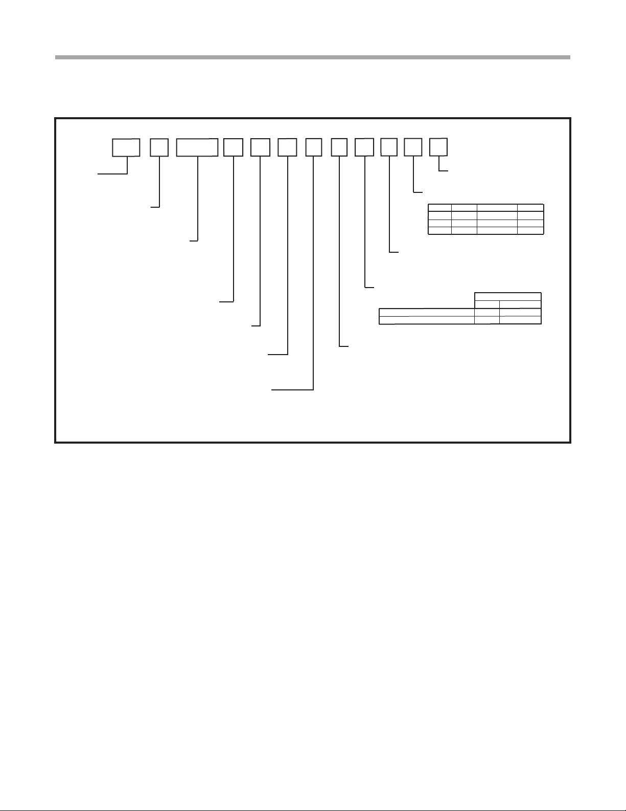
Tranquility®22 Digital (TZ)Series - 60Hz
Rev.: November 18, 2022
General Information
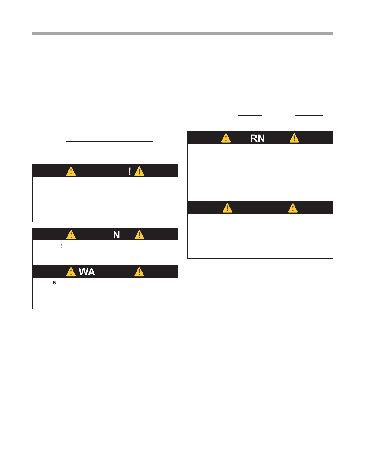
⚠
CAUTION!
⚠
⚠
CAUTION!
⚠
CAUTION! CUT HAZARD - Failure to follow this caution
may result in personal injury. Sheet metal parts may have
sharp edges or burrs. Use care and wear appropriate
protective clothing, safety glasses and gloves when
handling parts and servicing heat pumps.
INSPECTION
Upon receipt of the equipment, carefully check the shipment
against the bill of lading. Make sure all units and accessories
have been received. Inspect the packaging of each unit,
and inspect each unit for damage. Insure that the carrier
makes proper notation of any shortages or damage on all
copies of the freight bill and completes a common carrier
inspection report. Concealed damage not discovered during
unloading must be reported to the carrier within 15 days of
receipt of shipment. If not led within 15 days, the freight
company can deny the claim without recourse. NOTE: It is
the responsibility of the purchaser to file all necessary
claims with the carrier. Notify your equipment supplier of
all damage within fifteen (15) days of shipment.
STORAGE
Equipment should be stored in its original packaging in a
clean, dry area. Store units in an upright position at all times.
Stack units a maximum of 3 units high.
UNIT PROTECTION
Cover units on the job site with either the original packaging
or an equivalent protective covering. Cap the open ends
of pipes stored on the job site. In areas where painting,
plastering, and/or spraying has not been completed, all due
precautions must be taken to avoid physical damage to
the units and contamination by foreign material. Physical
damage and contamination may prevent proper start-up and
may result in costly equipment clean-up.
Examine all pipes, ttings, and valves before installing any of
the system components. Remove any dirt or debris found in
or on these components.
PRE-INSTALLATION
Installation, Operation, and Maintenance instructions are
provided with each unit. Horizontal equipment is designed for
installation above false ceiling or in a ceiling plenum. Other
unit congurations are typically installed in a mechanical
room. The installation site chosen should include adequate
service clearance around the unit. Before unit start-up,
read all manuals and become familiar with the unit and its
operation. Thoroughly check the system before operation.
PREPARE UNITS FOR INSTALLATION AS FOLLOWS:
1. Compare the electrical data on the unit nameplate with
ordering and shipping information to verify that the
correct unit has been shipped.
2. Keep the cabinet covered with the original packaging
until installation is complete and all plastering, painting,
etc. is nished.
3. Verify refrigerant tubing is free of kinks or dents and that
it does not touch other unit components.
4. Inspect all electrical connections. Connections must be
clean and tight at the terminals.
5. Remove any blower support packaging (water-to-air
units only).
6. Locate and verify any hot water generator (HWG),
hanger, or other accessory kit located in the compressor
section or blower section.
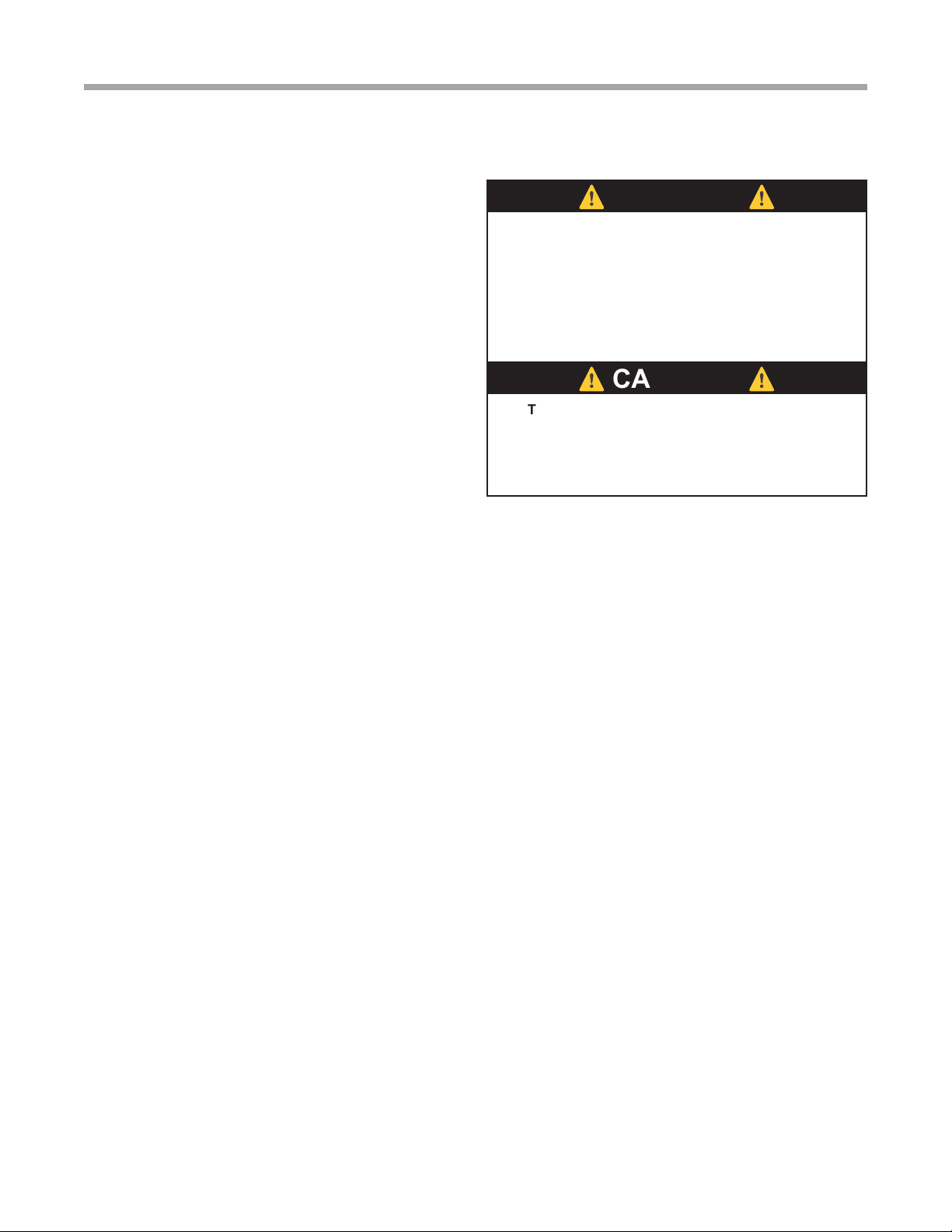
CAUTION! DO NOT store or install units in corrosive
environments or in locations subject to temperature or
humidity extremes (e.g., rooftops, etc. See Tables 12a
and 12b for acceptable temperature ranges). Corrosive
conditions and high temperature or humidity can
signicantly reduce performance, reliability, and service
life. Always move and store units in an upright position.
Tilting units on their sides may cause equipment damage.
INSTALLATION BEST PRACTICES
The installation of geothermal heat pump units and all
associated components, parts and accessories which
make up the GHP system shall be in accordance with the
regulations of ALL authorities having jurisdiction and MUST
conform to all applicable codes. It is the responsibility of
the installing contractor to determine and comply with ALL
applicable codes and regulations.
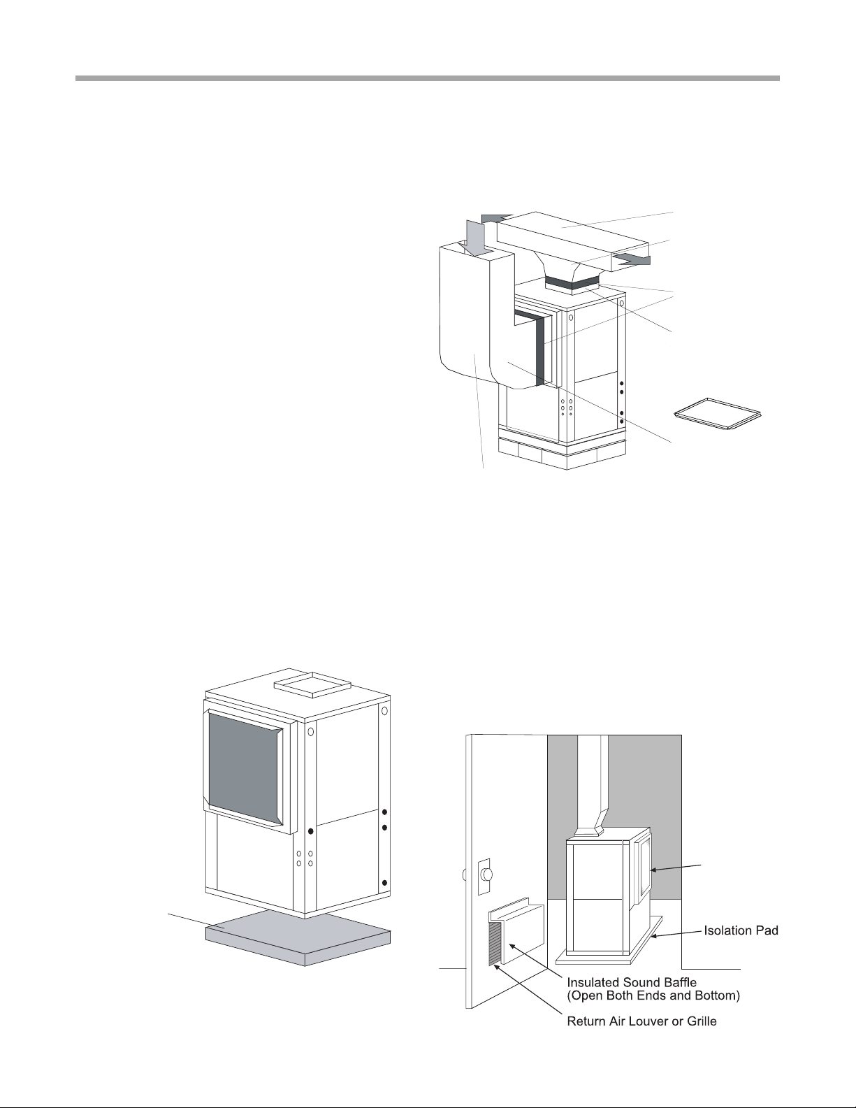
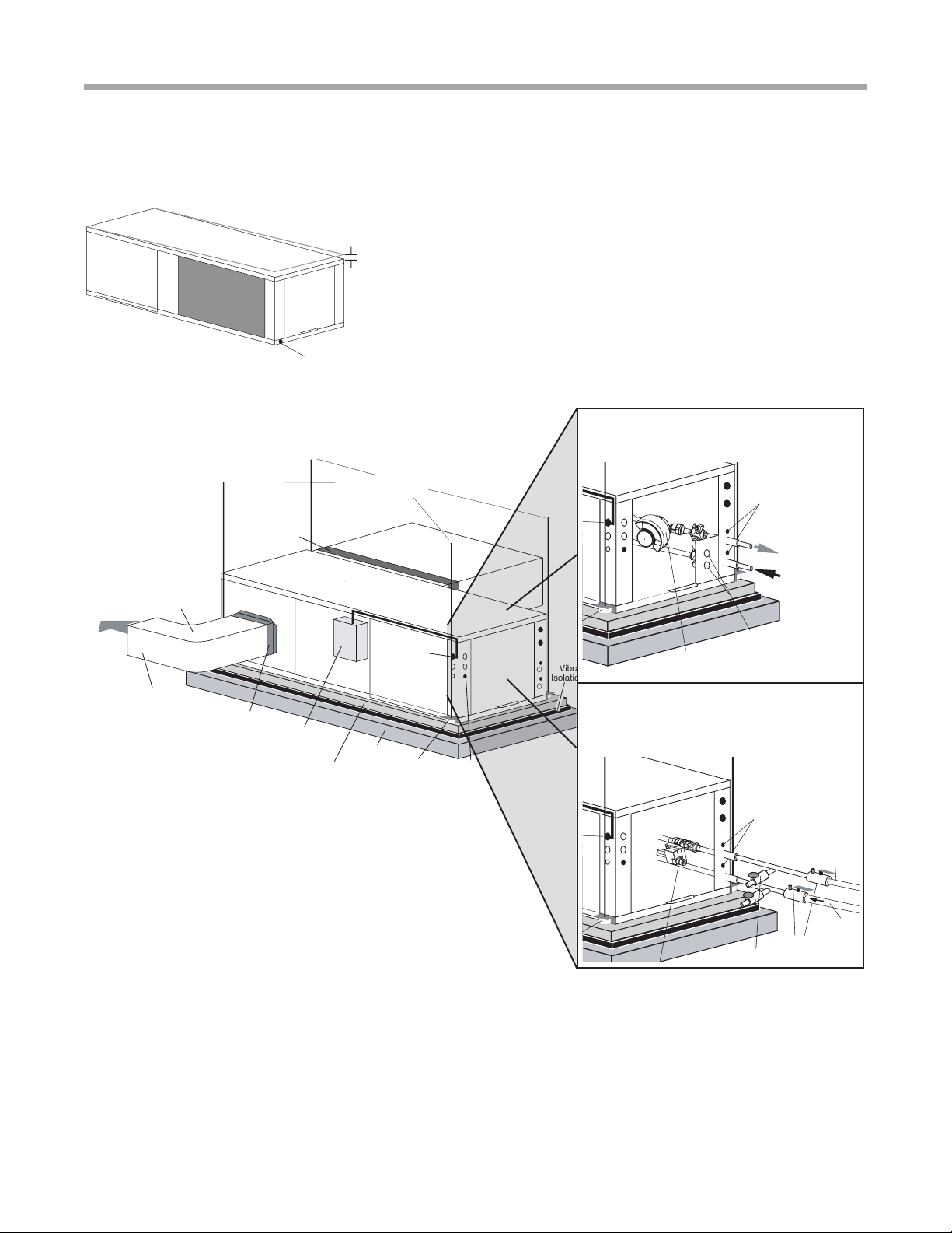
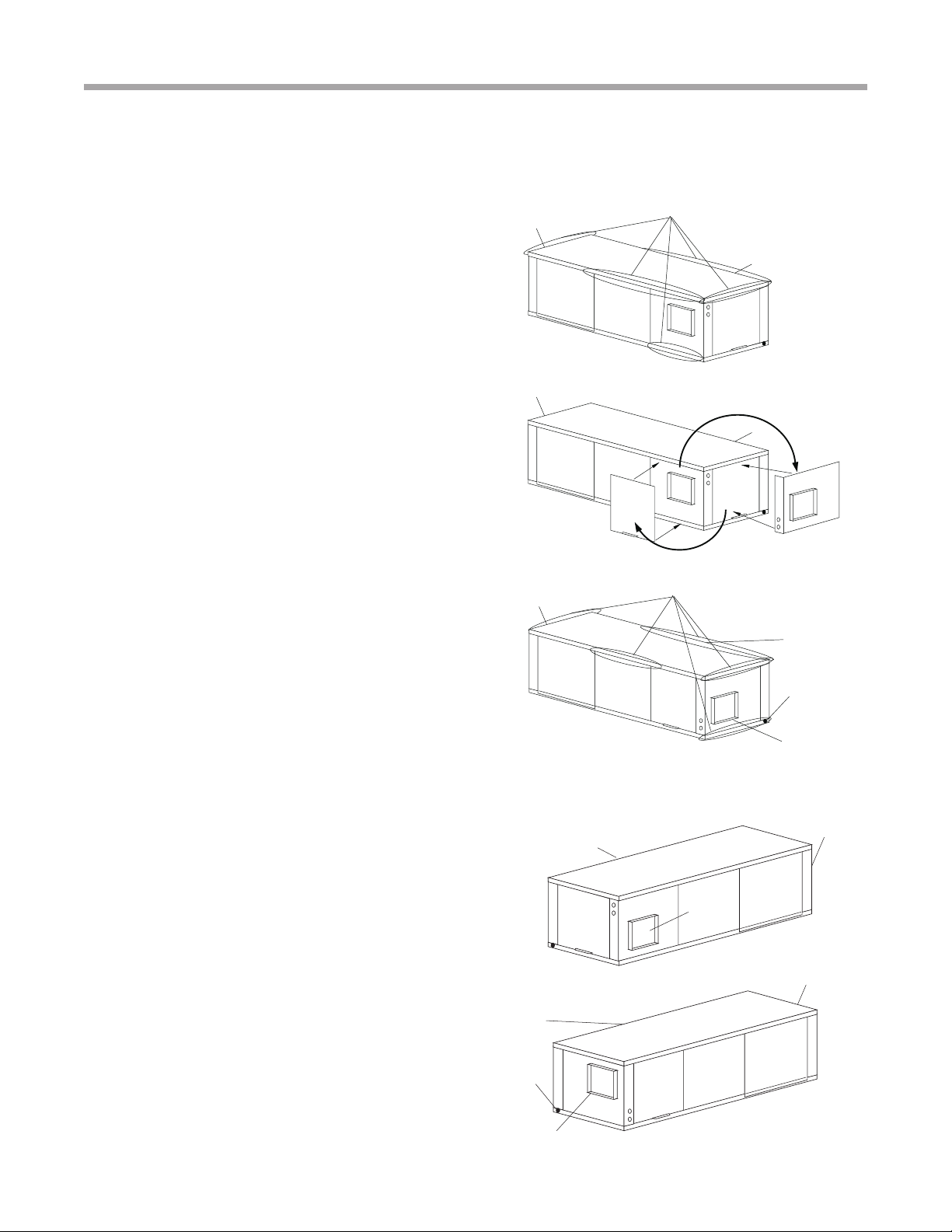
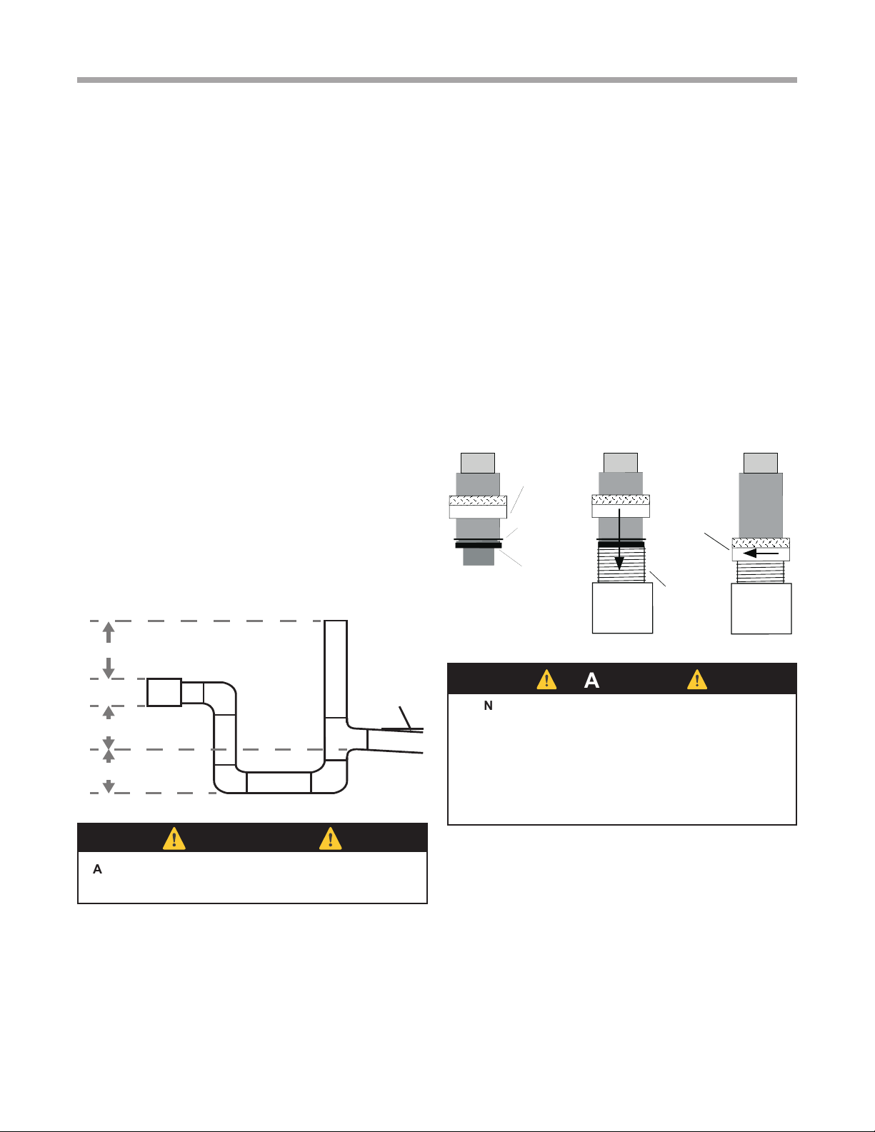
DUCT SYSTEM INSTALLATION
The duct system should be sized to handle the design
airow quietly. Refer to Figure 6a and 6b for horizontal duct
system details or Figure 2 for vertical duct system details.
A exible connector is recommended for both discharge
and return air duct connections on metal duct systems to
eliminate the transfer of vibration to the duct system. To
maximize sound attenuation of the unit blower, the supply
and return plenums should include internal berglass duct
liner or be constructed from duct board for the rst few
feet. Application of the unit to uninsulated ductwork in an
unconditioned space is not recommended, as the unit’s
performance will be adversely affected.
At least one 90° elbow should be included in the supply
duct to reduce air noise. If air noise or excessive air ow is
a problem, the blower speed can be changed. For airow
charts, consult catalog specications for the series and
model of the specic unit.
If the unit is connected to existing ductwork, a previous
check should have been made to insure that the ductwork
has the capacity to handle the airow required for the
unit. If ducting is too small, as in the replacement of a
heating only system, larger ductwork should be installed.
All existing ductwork should be checked for leaks and
repaired as necessary.