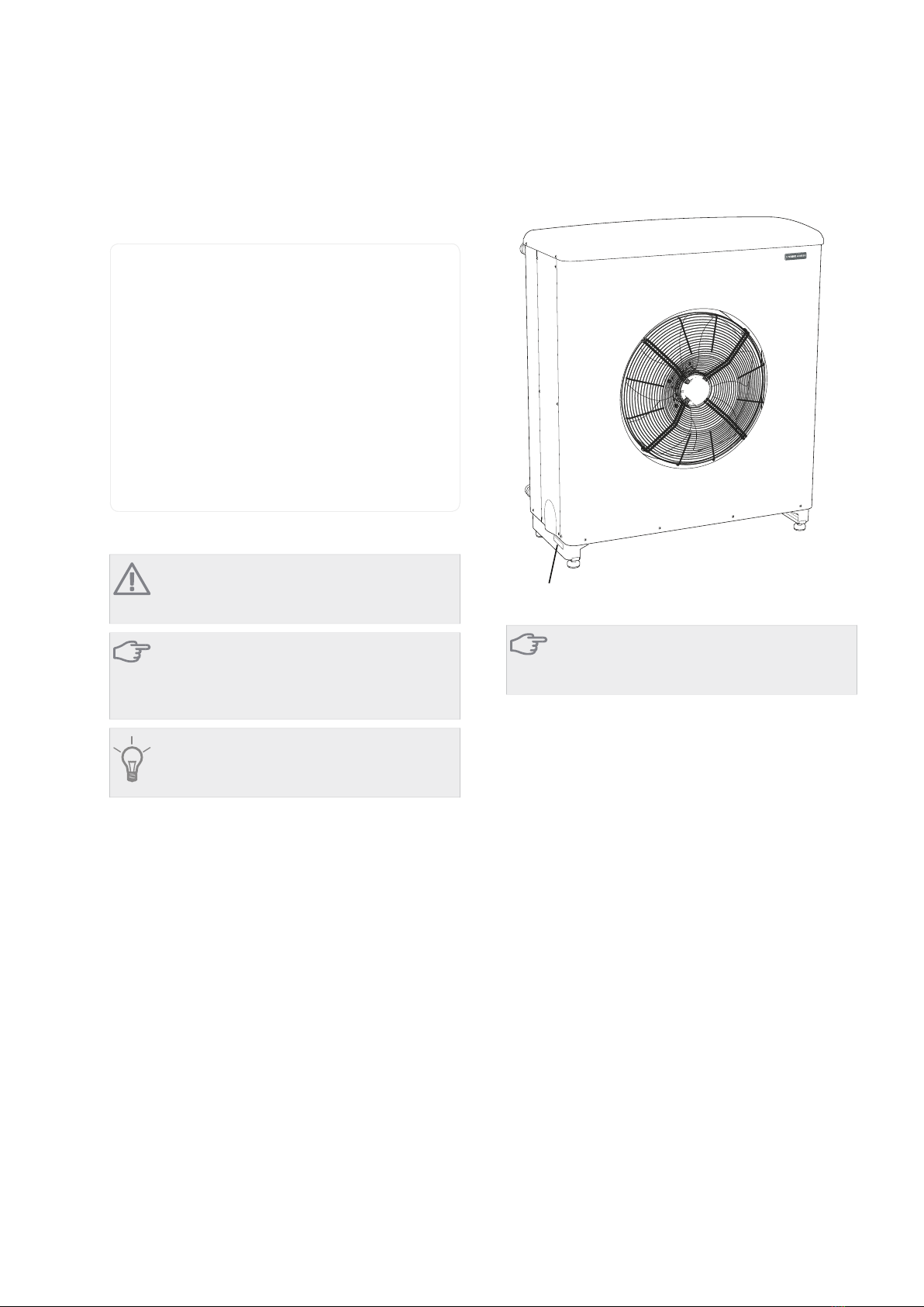
Condensation water trough
The condensation water trough is used to collect and
lead away most of the condensation water from AMB
30.
NOTE
It is important for the air collector module op-
eration that condensation water is led away
and that the drain for the condensation water
run off is not positioned so that it can cause
damage to the house.
NOTE
Pipe with heating cable for draining the con-
densation water trough are not included.
NOTE
The electrical installation and wiring must be
carried out under the supervision of an author-
ised electrician.
Caution
If none of the recommended alternatives is
used good lead off of condensation water
must be assured.
႑The condensation water (up to 100 litres/24 hrs)
collected in the trough should be routed via a pipe
to an appropriate drain, it is recommended that the
shortest outdoor stretch possible is used.
႑The section of the pipe that can be affected by frost
must be heated by the heating cable to prevent
freezing.
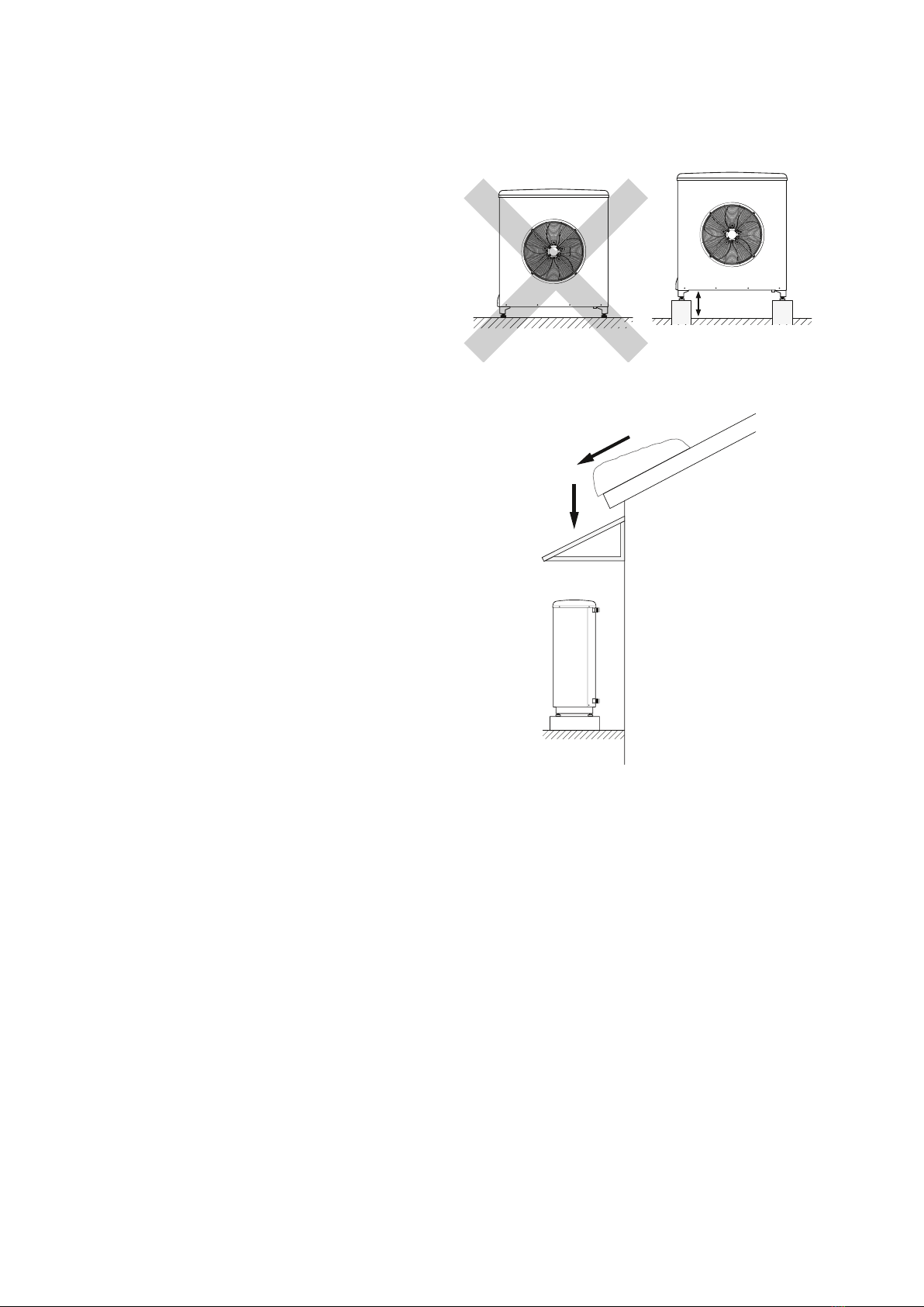
႑Route the pipe downward from AMB 30.
႑The outlet of the condensation water pipe must be
at a depth that is frost free or alternatively indoors
(with reservation for local ordinances and regula-
tions).
႑Use a water trap for installations where air circulation
may occur in the condensation water pipe.
႑Insulate the pipe (at least 19 mm of insulation) all
the way outside.
႑The insulation must be tight against the bottom of
the condensation water trough.
LEK
Fix the drainage hose to the connection under AMB
30 (recommended dimension 32 mm) with hose
clamps.
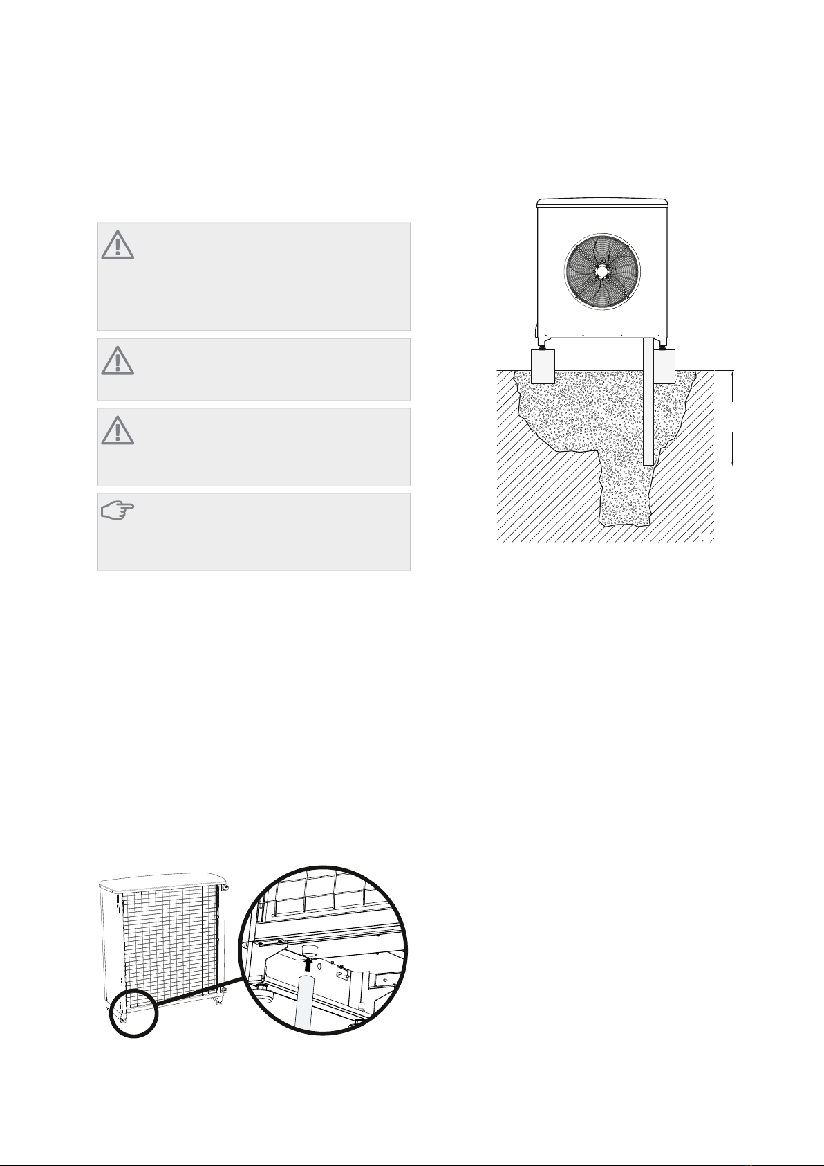
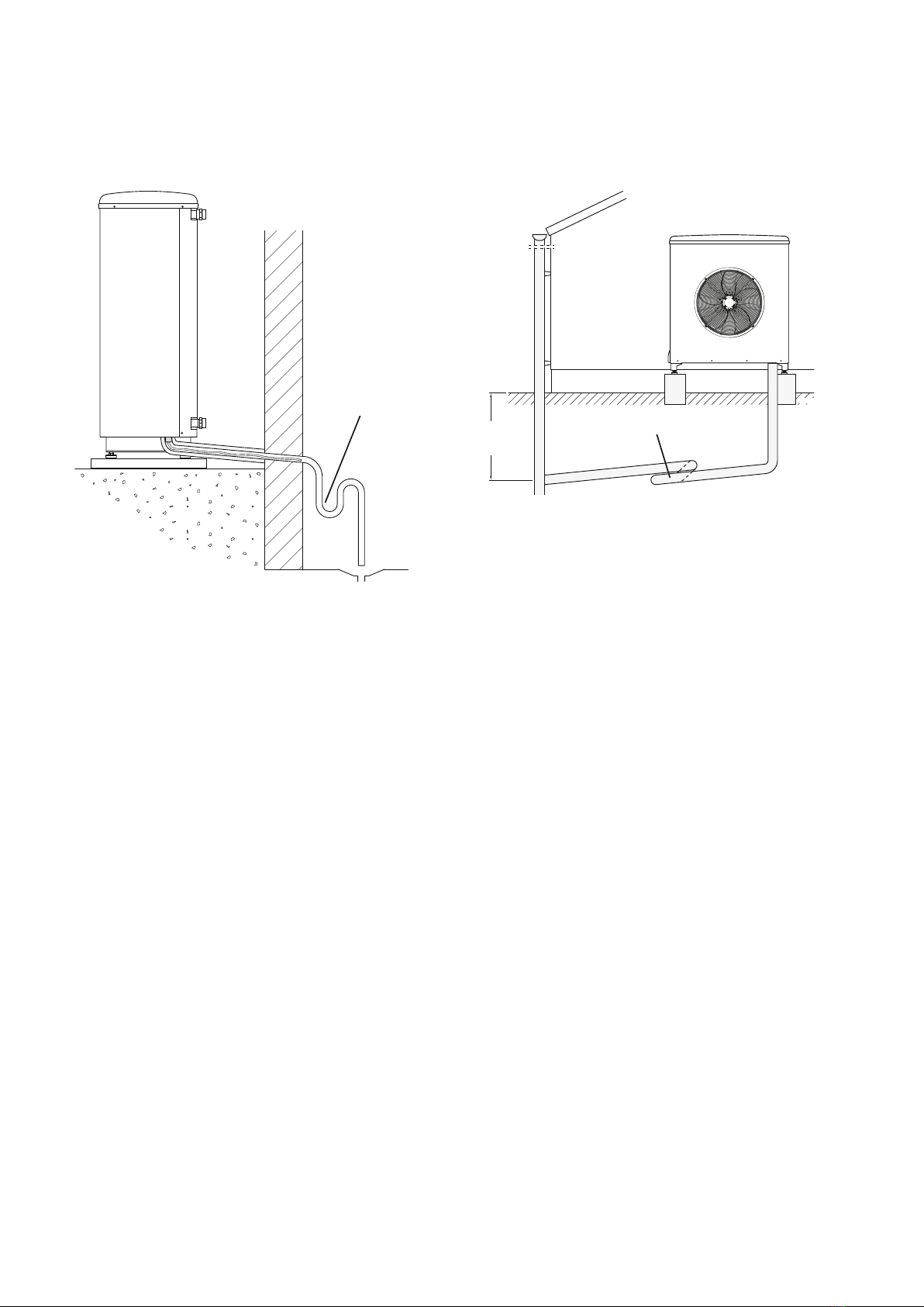
Recommended alternatives
Stone caisson
LEK
Frostfritt
djup
)URVW SURRI
GHSWK
If the house has a cellar the stone caisson must be po-
sitioned so that condensation water does not affect
the house. Otherwise the stone caisson can be posi-
tioned directly under the heat pump.
The outlet of the condensation water pipe must be at
frost free depth.
AMB 30Chapter 2 | Delivery and handling6