Nibe ESV 28 User manual

MAV 1313-1
ESV 28
231405 ESV 28
MONTERINGSANVISNING EXTRA SHUNT ESV 28 TILL HBS 16
SE
INSTALLATION INSTRUCTIONS EXTRA SHUNT ESV 28 FOR HBS 16
GB
MONTAGEANLEITUNG EXTRA MISCHGRUPPE ESV 28 FÜR HBS 16
DE
ASENNUSOHJE ESV 28 LISÄSHUNTTIRYHMÄLLE KÄYTETTÄVÄKSI HBS 16 KANSSA
FI
LEK
LEK


MONTERINGSANVISNING
ESV 28
Allmänt
Detta tillbehör används då NIBE SPLIT:s innemodul HBS
16 installeras i hus med två olika värmesystem som kräver
olika framledningstemperaturer, t.ex. då huset har både
radiatorsystem och golvvärmesystem. I nedanstående text
avser värmesystem 1 det system som kräver den högre
temperaturen och som kopplas in till den ordinarie fram-
lednings- respektive returledningsanslutningen. Värmesy-
stem 2 avser det värmesystem som arbetar med lägre
temperatur.
Vattenflödet i de två värmesystemen tillsammans bör inte
överstiga 2850 l/h (0,79 l/s).
OBS!
Detta tillbehör kräver tillbehöret ACK 28 för installa-
tion i HBS 16.
Innehåll
Kopparrör, kragat2st
3-ledare för cirkulationspump1st
Buntband4st
Värmeledningspasta2st
Isoleringstejp1st
Planpackning2st
Rundhylsa4st
Unionsmutter 1"2st
Cirkulationspump, EP21-GP201st
Kulventil2st
3-vägsventil1st
Aluminiumtejp (bitar)2st
Temperaturgivare, EP21-BT2 (framledningsgivare),
EP21-BT3 (returledningsgivare)
2st
Reglermotor, EP21-QN251st
Alphakontakt1st
3ESV 28
SE

Röranslutning HBS 16
Montering sker enligt följande:
႑Töm först pannvattenkärlet/värmesystemet om detta
är vattenfyllt.
႑Den extra värmebärarpumpen (EP21-GP20) placeras på
lämplig plats utanför HBS 16.
႑Shuntventilen (EP21-QN25) placeras på framledningen
efter HBS 16, före första radiator på värmesystem 1. Re-
turledningen från värmesystem 2 kopplas till shuntven-
tilen (EP21-QN25) samt till returledningen från värmesy-
stem 1, se bild på sida 5.
႑Framledningsgivaren (EP21-BT2) monteras på röret efter
värmebärarpumpen (EP21-GP20).
႑Returledningsgivaren (EP21-BT3) monteras på röret från
värmesystem 2.
႑Vid montering av givare skall värmeledningspasta använ-
das samt röret isoleras för att erhålla korrekt temperatur-
mätning.
OBS!
Vid felaktig montering kan funktionen äventyras.
LEK
Shuntventil, (EP21-QN25)
Anslutningar, Ø 28 mm
LEK
Retur
HBS 16 Framledning
1
2
3
Pump- och tryckfallsdiagram
0 200 400 600 800 1000 1200 1400 1600 1800 2000 2200 2400 2600
0
10
20
30
40
50
60
70
kPa
0,40,30,20,10 0,5 0,6 0,7
CP2
PP1
CP1 PP2
Speed I Speed II
Speed III
Flöde
l/h
l/s
Tillgängligt tryck,
kPa
Välj mellan sju inställningar på pumpen. Du kan välja
mellan tre olika konstanta hastigheter (I, II eller III) alterna-
tivt två olika proportionella (PP) respektive konstanta
tryckkurvor (CP) där 1 är lägsta och 2 högsta.
Shuntventilskaraktäristik
Flöde
(%)
10
0
20
30
40
50
60
70
80
90
100
01020
30 40 50 60 70 80 90
Vinkel (°)
2-3 (vinkel)
1-2 (rak)
Vinkel ( )
Flöde
(%)
2-3 (vinkel)
1-2 (rak)
Kvs-värde 12
Rekommenderad för över 200 m2golvvärmeyta.
ESV 284
SE

Principschema HBS 16 med ESV 28 - extra shunt
BT 1
AMS
HBS
HEV
Överströmnings-
ventil
EP21-QN25
EP21-GP20
EP21-BT2
EP21-BT3
CP1 Erf. säker-
hetsutr.
FL1
FQ1
AA25
Erforderlig säkerhetsutr.
Överströmnings-
ventil
Förklaring
Utjämningskärl UKVCP1Apparatlåda (RE10/RG10)AA25
Extra cirkulationspumpEP21-GP20Temperaturgivare, utomhusBT1
ShuntventilEP21-QN25Temperaturgivare, framledning 2EP21-BT2
Säkerhetsventil, varmvattenFL1Temperaturgivare, returledning 2EP21-BT3
Blandningsventil, varmvattenFQ1
5ESV 28
SE

Elinkoppling HBS 16
OBS!
All elektrisk inkoppling skall ske av behörig elektriker.
Elektrisk installation och ledningsdragning skall utfö-
ras enligt gällande bestämmelser.
HBS 16 ska vara spänningslös vid installation av ESV
28.
Elscheman finns i slutet av denna monteringsanvisning.
LEK
Elkoppling, X6
AA22:X4
EBV AA22
1. Tillbehöret ACK 28 installeras enligt medföljande
monteringsanvisning.
2. Givarna kopplas in med tvåledare (exempelvis EKXX
eller LiYY) enligt följande till effektvaktskortet
(EBV–AA22) se bild nedan:
Använd medföljande rundstiftshylsor för skarvning
mellan 2-ledarna och givarna BT2 och BT3.
-AA22
EBV-kort
>-EP21
Värmesystem 2 (Tillbehör)
Tempgivare framledning 2
Tempgivare returledning 2
X4
Den givare som används som framledningsgivare
(EP21-BT2) ansluts till position AA22:X4:7 och
AA22:X4:8 i effektvaktskortets nedre plint.
-
Returledningsgivaren (EP21-BT3) kopplas in till
position AA22:X4:5 och AA22:X4:6 på samma
kort.
-
Ventilställdonet (EP21-QN25) anslutes enligt följande:
Vit ledare (230 V signal) till fjäderplinten X6:8a-
Brun ledare (230 V signal) till fjäderplinten X6:7b-
Blå ledare (nolla) till fjäderplinten X6:6b-
Cirkulationspumpen (EP21-GP20) anslutes enligt följande:
Blå ledare (nolla) till fjäderplinten –X6:6a-
Gul/grön ledare (jordledare) till fjäderplinten –X6:5a-
Brun ledare (fas) till fjäderplinten –X6:4a-
7
8
6
4
5
3
2
1
Elkoppling,
X6
Vit
Brun
Blå
Gul/grön
Brun
ESV 286
SE

Montering av temperaturgivare
K
Temperaturgivaren monteras med buntband tillsammans
med värmeledningspasta och aluminiumtape.
Därefter skall den isoleras med medföljande isolertape.
OBS!
Givar- och kommunikationskablar får ej förläggas i
närheten av starkströmsledning.
Programinställningar
႑Välj “Service” i meny 8.1.1 för att få tillgång till meny 9.0
och dess undermenyer.
႑Välj sedan “Värme”, "Värme + Kyla" eller "Kyla" i meny
9.3.4, “Värmesystem 2”. Därmed blir meny 3.0 och dess
undermenyer åtkomliga.
႑I undermenyerna ställs nu kurvlutning 2, förskjutning
värmekurva 2 samt min- och maxnivåer för framlednings-
temperatur 2 in på samma sätt som för värmesystem 1
under meny 2.0.
Se också “Monterings- och skötselanvisning” för NIBE SPLIT.
7ESV 28
SE

ESV 288
SE

INSTALLATION INSTRUCTIONS
ESV 28
General
This accessory is used when the indoor module HBS 16 of
NIBE SPLIT is installed in houses with two different heating
systems that require different flow line temperatures, for
example, in cases where the house has both a radiator
system and an under floor heating system. In the following
text Heating system 1 covers the system that requires the
greater temperature and that is connected to the normal
flow line respectively return line connection. Heating sys-
tem 2 covers the heating system that works at the lower
temperature.
The water flow in the two heating systems should not ex-
ceed 2850 l/h (0,79 l/s).
NOTE
This accessory requires accessory ACK 28 for installa-
tion in HBS 16.
Contents
Copper pipe, collared2x
3 wire circulation pump1x
Cable ties4x
Heating pipe paste2x
Insulation tape1x
Flat gasket2x
Round sleeve4x
Swivel nut 1"2x
Circulation pump, EP21-GP201x
Ball valve2x
3-way valve1x
Aluminium tape (pieces)2x
Temperature sensor, EP21-BT2 (flow sensor), EP21-
BT3 (return sensor)
2x
Control motor, EP21-QN251x
Alpha switch1x
9ESV 28
GB

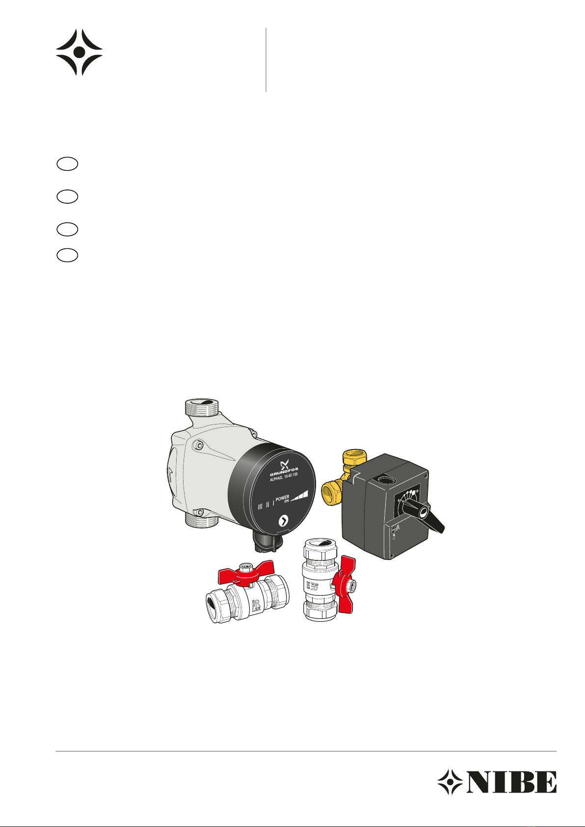
Pipe connections HBS 16
Install as follows:
႑First drain the boiler water reservoir/heating system if
filled with water.
႑Position the extra heat medium pump (EP21-GP20) in a
suitable location outside HBS 16.
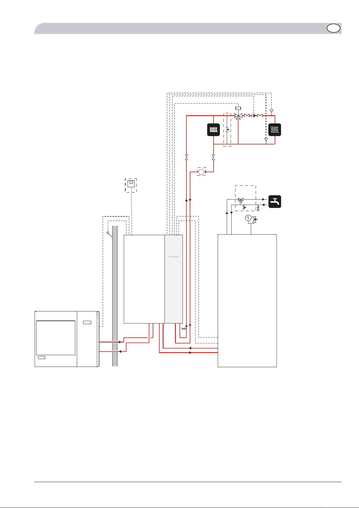
႑The shunt valve (EP21-QN25) is located on the flow line
after HBS 16, before the first radiator in the heating
system 1. The return line from heating system 2 is con-
nected to the shunt valve (EP21-QN25) and to the return
line from heating system 1, see illustration on page 11.
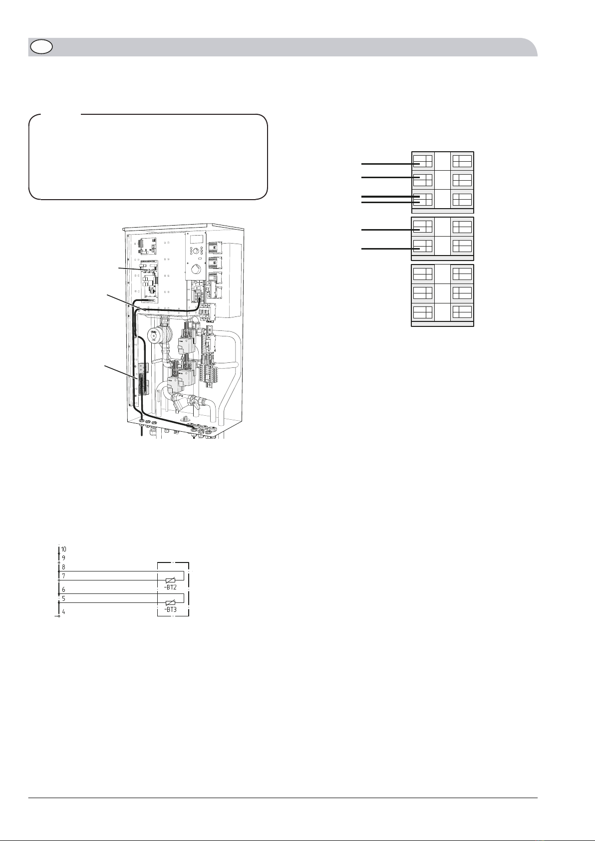
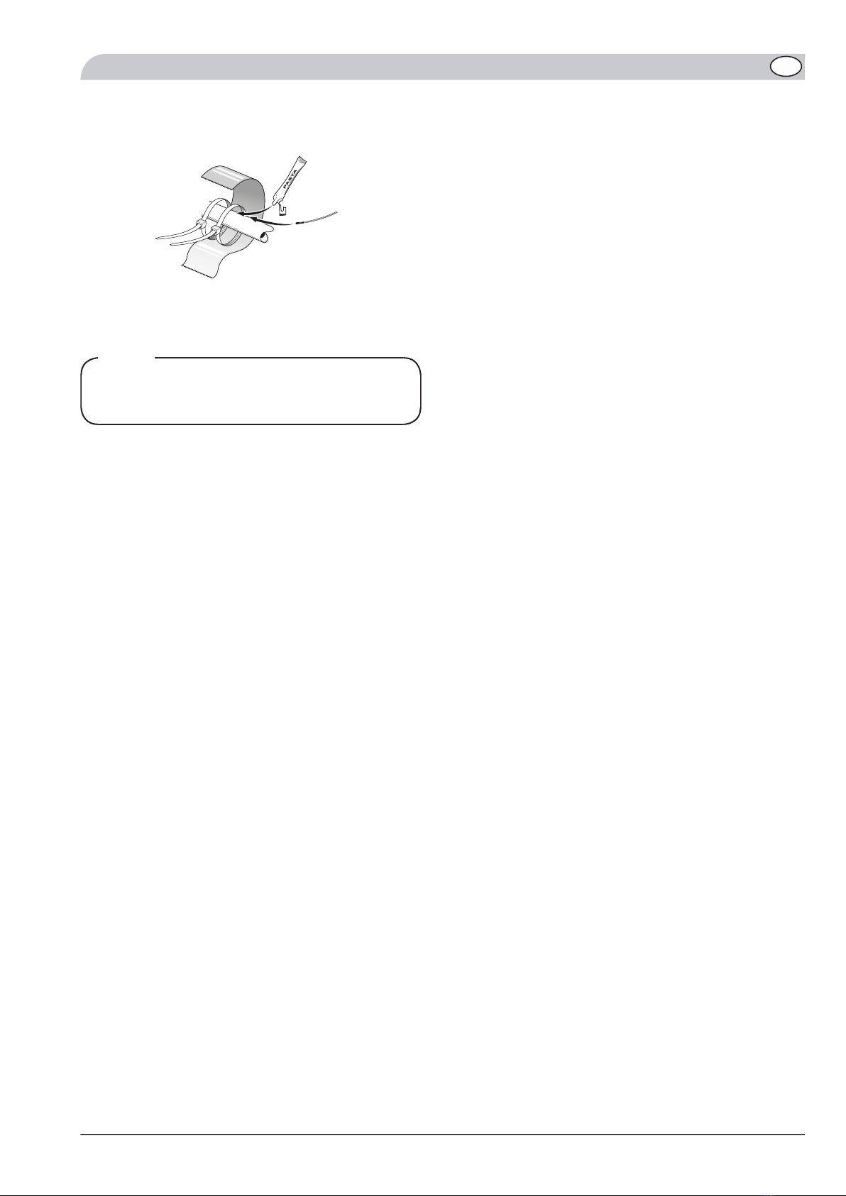
႑The flow sensor (EP21-BT2) is installed on the pipe after
the heat medium pump (EP21-GP20).
႑The return line sensor (EP21-BT3) is installed on the pipe
from heating system 2.
႑When installing the sensor, heat conducting paste must
be used and the pipe must be insulated to obtain the
correct temperature measurement.
NOTE
Incorrect installation can affect the function.
LEK
By-pass valve, (EP21-QN25)
Connections, Ø 28 mm
LEK
Return
HBS 16 Flow pipe
1
2
3
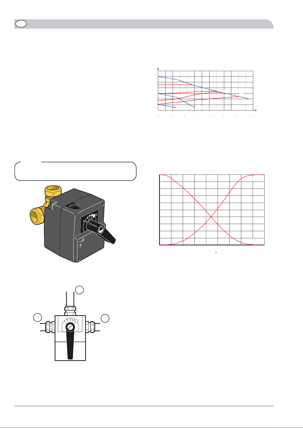
Pump and pressure drop diagrams
0 200 400 600 800 1000 1200 1400 1600 1800 2000 2200 2400 2600
0
10
20
30
40
50
60
70
kPa
0,40,30,20,10 0,5 0,6 0,7
CP2
PP1
CP1 PP2
Speed I Speed II
Speed III
Flow
l/h
l/s
Available pressure,
kPa
Choose between seven settings on the pump. You can
choose between three different constant speeds (I, II or
III) or two different curves, one proportional pressure (PP)
and one constant pressure (CP), where 1 is lowest and 2
highest.
Shunt valve characteristics
Flöde
(%)
10
0
20
30
40
50
60
70
80
90
100
01020
30 40 50 60 70 80 90
Vinkel (°)
2-3 (vinkel)
1-2 (rak)
Angle ( )
Flow
(%)
2-3 (angle)
1-2 (straight)
KVS value 12
Recommended for floor heating areas over 200 m2.
ESV 2810
GB

Outline diagram HBS 16 with ESV 28 - extra shunt
BT 1
AMS
HBS
HEV
Överströmnings-
ventil
EP21-QN25
EP21-GP20
EP21-BT2
EP21-BT3
CP1 Erf. säker-
hetsutr.
FL1
FQ1
AA25
Required safety equipment
Bypass
valve
Explanation
Buffer vessel UKVCP1Unit box (RE10/RG10)AA25
Extra circulation pumpEP21-GP20Temperature sensor, outdoorBT1
Shunt valveEP21-QN25Temperature sensor, supply line 2EP21-BT2
Safety valve, hot waterFL1Temperature sensor, return 2EP21-BT3
Mixer valve, hot waterFQ1
11ESV 28
GB

Electrical connection HBS 16
NOTE
All electrical connections must be carried out by an
authorised electrician.
Electrical installation and wiring must be carried out
in accordance with the stipulations in force.
HBS 16 must not be powered when installing ESV 28.
The electrical circuit diagram is at the end of these install-
ation instructions.
LEK
Electrical connection,
X6
AA22:X4
EBV AA22
1. The accessory ACK 28 is installed according to the
supplied installation instructions.
2. The sensors are connected by twin cables (for example
EKXX or LiYY) as follows for the load monitor card
(EBV–AA22) see image below:
Use the enclosed round pin sleeves for splicing
between the 2-cables and sensors BT2and BT3.
-AA22
EBV Control Card
>-EP21
Heating System 2 (Optional)
Temp. sensor supply line 2
Temp. sensor return 2
X4
The sensor used as flow sensor (EP21-BT2) is con-
nected to terminal AA22:X4:7 and AA22:X4:8 in
the load monitor card's lower terminal block.
-
The return line sensor (EP21-BT3) is connected to
terminal AA22:X4:5 and AA22:X4:6 on the same
card.
-
Connect valve actuator (EP21-QN25) as follows:
White cable (230 V signal) to spring terminal X6:8a-
Brown cable (230 V signal) to spring terminal X6:7b-
Blue cable (zero) to spring terminal X6:6b-
Connect circulation pump (EP21-GP20) as follows:
Blue cable (zero) to spring terminal –X6:6a-
Yellow/green cable (earth cable) to spring terminal –X6:5a-
Brown cable (phase) to spring terminal –X6:4a-
7
8
6
4
5
3
2
1
Electrical
connection,
X6
White
Brown
Blue
Yellow/green
Brown
ESV 2812
GB

Temperature sensor installation
K
Install the temperature sensor with cable ties with the heat
conducting paste and aluminium tape.
Then insulate with supplied insulation tape.
NOTE
Sensor and communication cables must not be placed
near power cables.
Program settings
႑Select “Service” in menu 8.1.1 to gain access to menus
9.0 and the sub-menus.
႑Then select “Heating”, "Heating + Cooling" or "Cooling"
in menu 9.3.4, “Heating system 2”. Menu 3.0 and its sub-
menus become accessible.
႑In the sub-menus the curve co-efficient 2, offset heat
curve 2 and min- and max levels for the flow line temper-
ature 2 are set in the same way as heat system 1 under
menu 2.0.
See “Installation and Maintenance Instructions” for NIBE
SPLIT.
13ESV 28
GB

ESV 2814
GB

MONTAGEANLEITUNG
ESV 28
Allgemeines
Dieses Zubehör kommt zum Einsatz, wenn das NIBE SPLIT-
Innenmodul HBS 16 in einem Haus mit zwei verschiedenen
Heizsystemen installiert ist, die unterschiedliche Vorlauf-
temperaturen erfordern, z.B. wenn ein Gebäude über
Heizkörper und Fußbodenheizung verfügt. Im folgenden
Text gilt Heizkreis 1 als das System, das die höhere Tempe-
ratur erfordert und das mit dem normalen Vor- bzw.
Rücklaufanschluss verbunden wird. Als Heizsystem 2 gilt
das System, das mit der niedrigeren Temperatur arbeitet.
Der kombinierte Wasserdurchfluss in beiden Heizsystemen
darf 2850 l/h (0,79 l/s) nicht überschreiten.
HINWEIS!
Dieses Zubehör erfordert das Zubehör ACK 28 für die
Installation in HBS 16.
Inhalt
Kupferrohr, mit Flansch2 St.
3-Leiter-Umwälzpumpe1 St.
Kabelbinder4 St.
Wärmeleitpaste2 St.
Isolierband1 St.
Flachdichtung2 St.
Buchse4 St.
Überwurfmutter 1"2 St.
Umwälzpumpe, EP21-GP201 St.
Kugelventil2 St.
3-Wegeventil1 St.
Aluminiumklebeband (Abschnitte)2 St.
Fühler, EP21-BT2 (Vorlauffühler), EP21-BT3
(Rücklauffühler)
2 St.
Stellantrieb, EP21-QN251 St.
Alpha-Kontakt1 St.
15ESV 28
DE

Rohranschluss HBS 16
Führen Sie die Montage wie folgt durch:
႑Entleeren Sie zuerst das Wasser aus dem Heizwasserge-
fäß/Heizkreis.
႑Positionieren Sie die zusätzliche Heizungsumwälzpumpe
(EP21-GP20) an einer geeigneten Stelle außerhalb von
HBS 16.
႑Bringen Sie das Mischventil (EP21-QN25) am Vorlauf
hinter HBS 16 und vor dem ersten Heizkörper für Heiz-
kreis 1 an. Verbinden Sie die Rücklaufleitung von Heiz-
kreis 2 mit dem Mischventil (EP21-QN25) und der Rück-
laufleitung vom Heizkreis 1, siehe Abb. auf Seite 17.
႑Der Vorlauffühler (EP21-BT2) wird am Rohr nach der
Heizungsumwälzpumpe (EP21-GP20) montiert.
႑Der Rücklauffühler (EP21-BT3) wird am Rohr von Heiz-
kreis 2 montiert.
႑Verwenden Sie bei der Fühlermontage Wärmeleitpaste
und isolieren Sie das Rohr, um eine korrekte Temperatur-
messung zu gewährleisten.
HINWEIS!
Bei einer falschen Montage kann die Funktionsweise
beeinträchtigt werden.
LEK
Mischventil, (EP21-QN25)
Anschlüsse, Ø 28 mm
LEK
Rücklauf
HBS 16 Vorlauf
1
2
3
Pumpenkennliniendiagramm
0 200 400 600 800 1000 1200 1400 1600 1800 2000 2200 2400 2600
0
10
20
30
40
50
60
70
kPa
0,40,30,20,10 0,5 0,6 0,7
CP2
PP1
CP1 PP2
Speed I Speed II
Speed III
Fluss
l/h
l/s
Verfügbarer Druck,
kPa
Es stehen sieben Pumpeneinstellungen zur Auswahl. Sie
können zwischen drei festen Drehzahlen (I, II oder III) bzw.
zwei proportionalen (PP) oder konstanten Druckkurven
(CP) wählen, wobei 1 der niedrigste und 2 der höchste
Wert ist.
Mischventilcharakteristik
Flöde
(%)
10
0
20
30
40
50
60
70
80
90
100
01020
30 40 50 60 70 80 90
Vinkel (°)
2-3 (vinkel)
1-2 (rak)
Winkel ( )
Durchfluss
(%)
2-3 (Winkel)
1-2 (gerade)
KVS-Wert 12
Empfohlen für eine Fußbodenheizfläche über 200 m2.
ESV 2816
DE

Prinzipskizze HBS 16 mit ESV 28 - zusätzliches Mischventil
BT 1
AMS
HBS
HEV
Överströmnings-
ventil
EP21-QN25
EP21-GP20
EP21-BT2
EP21-BT3
CP1 Erf. säker-
hetsutr.
FL1
FQ1
AA25
Erforderliche Sicherheitsausr.
Überström-
ventil
Erklärung
Pufferspeicher UKVCP1Gerätegehäuse (RE10/RG10)AA25
Zusätzliche UmwälzpumpeEP21-GP20AußentemperaturfühlerBT1
MischventilEP21-QN25Fühler, Vorlauf 2EP21-BT2
Sicherheitsventil, BrauchwasserFL1Fühler, Rücklauf 2EP21-BT3
Mischventil, BrauchwasserFQ1
17ESV 28
DE

Elektrischer Anschluss HBS 16
HINWEIS!
Alle elektrischen Anschlüsse müssen von einem be-
fugten Elektriker ausgeführt werden.
Bei der Elektroinstallation und beim Verlegen der
Leitungen sind die geltenden Vorschriften zu berück-
sichtigen.
HBS 16 darf bei der Installation von ESV 28 nicht mit
Spannung versorgt werden.
Der Schaltplan befindet sich am Ende dieser Montagean-
leitung.
LEK
Elektrischer
Anschluss, X6
AA22:X4
EBV AA22
1. Das Zubehör ACK 28 wird gemäß der beiliegenden
Montageanleitung installiert.
2. Die Fühler werden wie folgt per Zweileiter (z.B. EKXX
oder LiYY) mit der Leistungswächterplatine verbunden
(EBV–AA22) siehe Abbildung unten.
Verwenden Sie die folgenden Rundstifthülsen, um
2-Leiter sowie Fühler BT2 und BT3 zu verbinden.
-AA22
EBV-Karte
>-EP21
Heizsystem 2 (Zubehör)
Temp.fühler, Vorlauf 2
Temp.fühler, Rücklauf 2
X4
Der als Vorlauffühler verwendete Fühler (EP21-
BT2) wird mit Position AA22:X4:7 und AA22:X4:8
an der unteren Anschlussklemme der Leistung-
swächterplatine verbunden.
-
Rücklauffühler (EP21-BT3) wird mit Position
AA22:X4:5 und AA22:X4:6 an derselben Platine
verbunden.
-
Ventilstellvorrichtung (EP21-QN25) wird wie folgt ange-
schlossen:
Weißer Leiter (230-V-Signal) an Federklemme X6:8a-
Brauner Leiter (230-V-Signal) an Federklemme X6:7b-
Blauer Leiter (Nullleiter) an Federklemme X6:6b.-
Umwälzpumpe (EP21-GP20) wird wie folgt angeschlossen:
Blauer Leiter (Nullleiter) an Federklemme -X6:6a-
Gelber/grüner Leiter (Erdleiter) an Federklemme -X6:5a-
Brauner Leiter (Phase) an Federklemme -X6:4a-
7
8
6
4
5
3
2
1
Elektrischer
Anschluss,
X6
Weiß
Braun
Blau
Gelb/Grün
Braun
ESV 2818
DE

Fühlermontage
K
Der Fühler wird mit Kabelbinder, Wärmeleitpaste und
Aluminiumband angebracht.
Anschließend ist er mit dem beiliegenden Isolierband zu
umwickeln.
HINWEIS!
Fühler- und Kommunikationskabel dürfen nicht in
der Nähe von Starkstromleitungen verlegt werden.
Programmeinstellungen
႑Durch Auswahl von "Service" in Menü 8.1.1 erhalten Sie
Zugriff auf Menü 9.0 und die zugehörigen Untermenüs.
႑Wählen Sie anschließend “Heizung”, "Heizung + Küh-
lung" oder "Kühlung" im Menü 9.3.4, "Heizkreis 2" aus.
Dadurch erhalten Sie Zugriff auf Menü 3.0 und die zuge-
hörigen Untermenüs.
႑In den Untermenüs werden Heizkurvenverlauf 2, Paral-
lelverschiebung der Heizkurve 2 sowie Minimal- und
Maximalwerte für Vorlauftemperatur 2 auf dieselbe
Weise wie für Heizkreis 1 unter Menü 2.0 eingestellt.
Siehe auch "Montage- und Wartungsanleitung" für NIBE
SPLIT.
19ESV 28
DE

ESV 2820
DE
Table of contents
Languages: