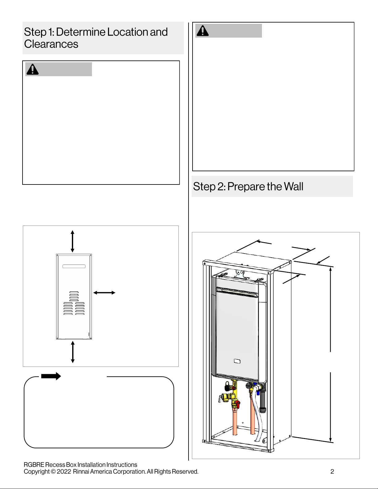
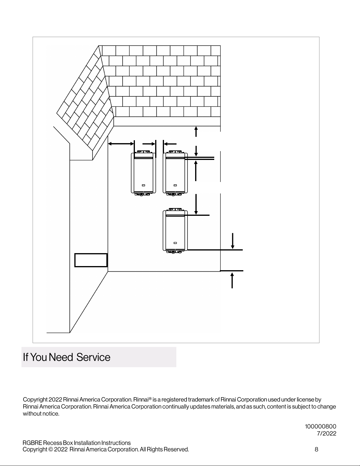
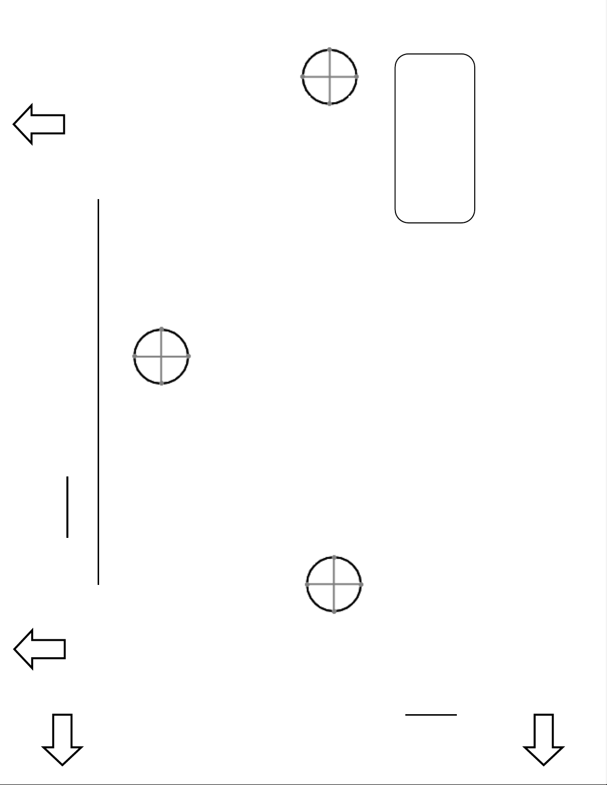
manuals.online logo
Brands
  1. Home
  2. •
  3. Brands
  4. •
  5. Rinnai
  6. •
  7. Water Heater Accessories
  8. •
  9. Rinnai RGBRE User manual

Rinnai RGBRE User manual

Item # Item Qty
1Recess Box 1
2Front Door Panel 1
3Hanging Bracket 1
4Mounng Screw (for top mounng bracket) 1
5Lock Nut with Washer 4
6Locking Bracket 1
7Instrucons (includes piping template) 1
• Standard plumbing tools such as pliers, pipe wrenches and screwdrivers
• Isolaon Valve Kit (Included with REP Models)
• Sealant and Caulk Gun
• Drill (for drilling the piping connecons)
• Screws (galvanized or stainless steel to secure the recess box to the building structure)
• Phillips Head Screwdriver
Before installaon, please make sure all parts are located inside the product box.
IMPORTANT: The
template used to
drill the piping
connecons is
located on the last
page of this
document.
WARNING
• Failure to correctly assemble the components according to these instrucons may result in electric shock, injury,
or death.
• A trained and qualied professional must install and inspect the recess box before use.
• Warranty will be voided due to any improper installaon.
• For outdoor installaon only.
• Make sure the recess box is accessible for servicing and maintenance of the water heater.
• RE199e (REU-VE2737WD-US)
• REP199e (REU-VEP2730WD-US)
• RE180e (REU-VE2432WD-US)
• RE160e (REU-VE2125WD-US)
• REP160e (REU-VEP2125WD-US)
• RE140e (REU-VE1720WD-US)
Recess Box Part Number RGBRE
For Use with Rinnai Tankless
Water Heater Models:
Figure 1
1. Determine a suitable locaon for the recess box
that meets the installaon clearances shown
below (Figure 2).
31 in. (0.79 m) to a sot or
eve vent, or to a porch or deck
9 in. (229 mm)
to inside corner
12 in. (0.30 m) to ground/snow line
Prepare an opening for the recess box to the following
dimensions below (Figure 3). The recess box is designed
to t between 16 in. (41 cm) centered framing.
WARNING
• Local building codes may restrict the clearances
shown in this secon. If you are unsure if the
clearances are acceptable in your area, consult
with local building ocials to verify prior to
proceeding with installaon.
• Clearance to the gas meter and electric meter shall
be in accordance with local codes and the
requirements of the gas supplier or electric
supplier.
• Ensure all clearances are met per the Rinnai
Tankless Water Heater Installaon and Operaon
Manual.
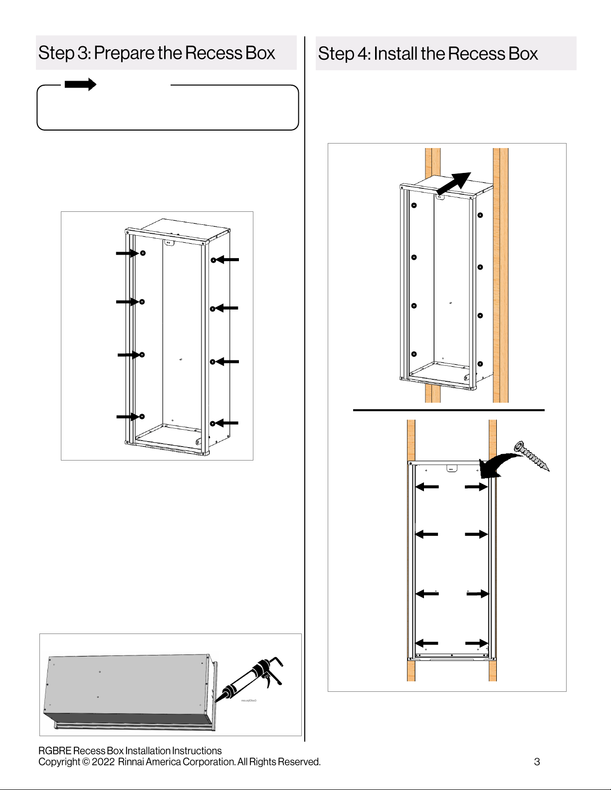
• This recess box is designed to be installed between
2 studs in a wall cavity. Do not install the recess
box in any other type of conguraon. Warranty
will be voided due to any improper installaon.
IMPORTANT
• All dimensions are from edge of box.
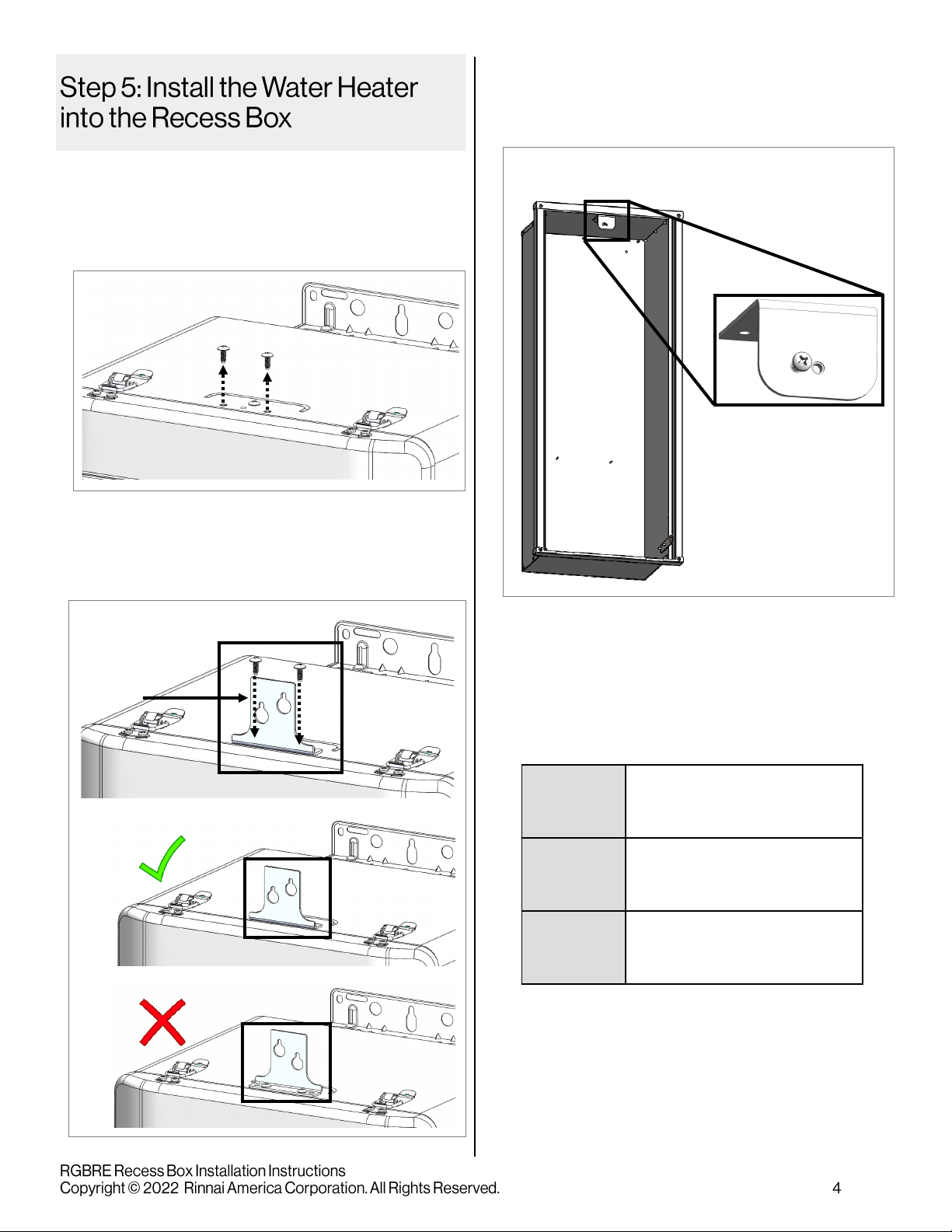
• Tankless water heater/recess box assembly
are zero inches to all surfaces of the recess
box. A 24 in. (610 mm) clearance to
combusbles and non-combusbles must be
maintained from the front of the unit for
servicing.
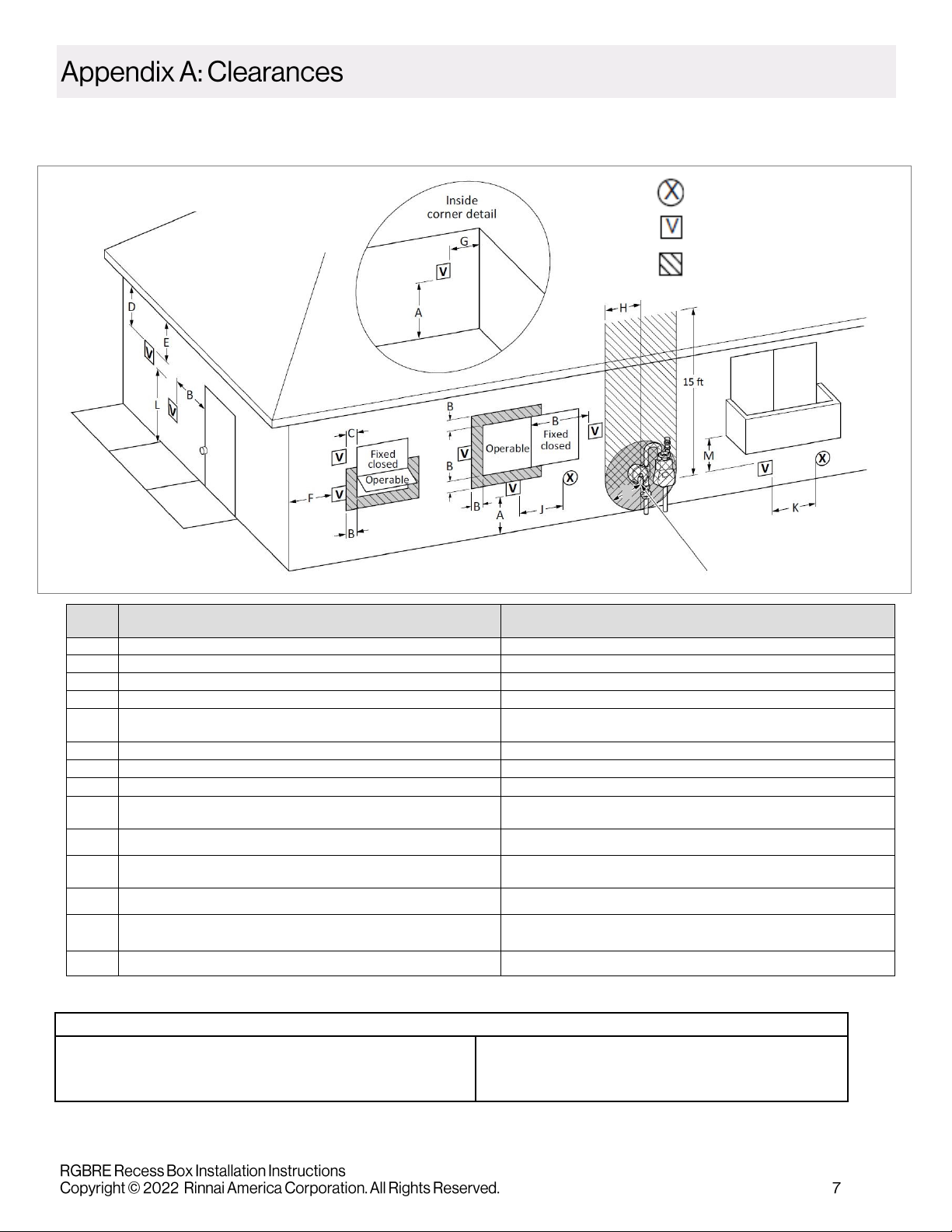
Below are general clearance requirements:
All clearances must conform with local codes or, in
the absence of local codes, with the Naonal Fuel
Gas Code, ANSI Z223.1/NFPA 54, or the Natural Gas
and Propane Installaon Code, CSA B149.1 (also
shown in the Rinnai Tankless Water Heater
Installaon and Operaon Manual).
If you do not have access to the above Standards or
the Rinnai Tankless Water Heater Installaon and
Operaon Manual, an excerpt has been provided in
Appendix A of this document.
WARNING
39.8 in.
101 cm
10.2 in.
25.9 cm
14.5 in.
36.8 cm
Figure 3
Figure 2
IMPORTANT
1. Drill 4 holes spaced out along the length of the le
and right sides of the recess box (Figure 4) (hole sizes
dependent on screw size). The recess box is designed
to t between two studs and secured through these
holes.
2. Using the supplied piping template (last page in this
document), drill 4 holes in the boom of the recess
box to accommodate the hot water, cold water, gas
and electric lines. The pressure relief valve (PRV)
locaon is not idened on the template.
If needed, holes can be drilled on the sides of the
recess box to accommodate the hot water, cold water,
gas and electric lines. Watch for interference with the
framing stud before drilling the holes.
3. Apply a 3/8 in. bead of sealant along the back of the
recess box ange (Figure 5).
Posion and secure the recess box to the building
structure with suitable screws (galvanized or stainless
steel) through the 8 holes in the sides (4 holes on the le
side and 4 holes on the right side) (Figure 6).
Seal all sides
Hole size and spacing on images are not to scale; they
are for illustrave purposes only.
Figure 6
Figure 5
Figure 4
Model #:
Serial #:
Gas Type: ❑ Natural Gas
❑ Propane
1. Aach the hanging bracket (supplied) to the water
heater:
Remove the 2 screws on the top of the water
heater (Figure 7).
Posion the hanging bracket as shown below
and re-insert the 2 screws. Pay close aenon
to the orientaon of the bracket (Figure 8).
2. Install the mounng screw (supplied) halfway
through the recess box top mounng bracket
(Figure 9).
3. Copy the water heater serial number and model
number from the data plate located on the le side
of the water heater onto the scker located inside
the recess box cover. You will need to know this
informaon for any future warranty or service work.
A
B
Hanging
Bracket
Figure 7
Figure 8
Figure 9
4. Li the water heater into the recess box and guide the
hanging bracket over the mounng screw (Figure 10).
6. Tighten the top mounng bracket screw (Figure 12).
The hanging bracket on the water heater may bend
slightly during ghtening.
5. Guide the water heater’s boom bracket over the 2
studs in the boom poron of the recess box (Figure
11).
Aach 2 lock nuts and washers (supplied) to the
studs and ghten.
Tighten the screw
1. Install the locking bracket with the 2 lock nuts and
washers (supplied) (Figure 13).
x2
x2
x2
x2
Figure 12
Figure 10
Figure 11
Figure 13
1. Check for gas and water leaks.
2. Install the recess box front door panel by inserng
the top end rst and then pressing the boom end
into the recess box (Figure 16).
1. Seal all access hole penetraons with sealant to
prevent moisture from leaking out of the recess box
(Figure 15).
1. Remove the caps from the water heater pipes and
install the isolaon valve kit (eld-supplied).
2. Install the pipes through the drilled access holes in
the recess box (Figure 14).
3. Connect gas, water and electric service to the water
heater. A waterproof electrical outlet can be ed
inside.
The installaon must conform with local codes or, in
the absence of local codes, with the Naonal Fuel
Gas Code, ANSI Z223.1/NFPA 54, or the Natural Gas
and Propane Installaon Code, CSA B149.1. If
installed in a manufactured home, the installaon
must conform with the Manufactured Home
Construcon and Safety Standard, Title 24 CFR, Part
3280 and/or CAN/CSA Z240 MH Series, Mobile
Homes.
The appliance, when installed, must be electrically
grounded in accordance with local codes or, in the
absence of local codes, with the Naonal Electrical
Code, ANSI/NFPA 70, or the Canadian Electrical
Code, CSA C22.1.
2
1
Figure 15
GAS
COLD
HOT
ELECTRIC
Figure 14
Figure 16
Other than Direct Vent (Outdoor): Terminaon Clearances
Figure 17: Outdoor Terminaon Clearances
Regulator vent outlet
I
AIR SUPPLY INLET
VENT TERMINAL
AREA WHERE TERMINAL IS
NOT PERMITTED
U.S. Installaons1
(ANSI Z223.1/NFPA 54)
Ref Descripon Other than direct vent (Outdoor unit)
AClearance above grade, veranda, porch, deck, or balcony 12 in. (30 cm)
BClearance to window or door that may be opened 4  (1.2 m) below or to side of opening; 1  (300 mm) above opening
CClearance to permanently closed window *
DVercal clearance to venlated sot, located above the terminal within a
horizontal distance of 2  (61 cm) from the center line of the terminal *
EClearance to unvenlated sot *
FClearance to outside corner *
GClearance to inside corner 12 in.
HClearance to each side of center line extended above meter/regulator
assembly *
IClearance to service regulator vent outlet *
JClearance to non-mechanical air supply inlet to building or the
combuson air inlet to any other appliance 4  (1.2 m) below or to side of opening; 1  (300 mm) above opening
KClearance to a mechanical air supply inlet 3  (91 cm) above if within 10  (3 m) horizontally
LClearance above paved sidewalk or paved driveway located on public
property
Vents for Category II and IV appliances cannot be located above public
walkways or other areas where condensate or vapor can cause a nuisance
or hazard.
MClearance under veranda, porch, deck, or balcony *
Clearance to opposite wall is 24 in. (60 cm).
[1] A vent shall not terminate directly above a sidewalk or paved driveway that
is located between two single family dwellings and serves both dwellings.
[2] Permied only if veranda, porch, deck, or balcony is fully open on a mini-
mum of two sides beneath the oor.
* Clearances are in accordance with local installaon codes and the
requirements of the gas supplier.
Notes: 1In accordance with the current ANSI Z223.1/NFPA 54, Naonal Fuel Gas Code.
If locally adopted installaon codes specify clearances dierent than those illustrated, then the most stringent clearance shall prevail. 36 inches minimum from the
top of the water heater to the overhang. The area under the overhang must be open on 3 sides.
Contact Rinnai Customer Care at 1-800-621-9419.
Terminaon Clearance for External (Outdoor) Water Heaters
Corner 12 in. (0.30 m) from
ground ancipated
snow line
36 in. (0.91 m) to venlated or unvenlated
sot or eve vent; or to a deck or porch
60 in. (1.52 m) vercally between terminals
2 in.
(51 mm)
12 in.
(0.30 m)
Figure 18
ALIGN THE PAPER EDGE WITH THE
BACK OF THE RECESS BOX
ALIGN THE PAPER EDGE WITH THE
LEFT OF THE RECESS BOX
HOT
COLD
GAS
PRV AND ELECTRIC LOCATION NOT
IDENTIFIED
This Template is for RE and REP Outdoor Models Only
Hot, Cold and Gas
Connecons are for
RE and REP models.

Popular Water Heater Accessories manuals by other brands

PAW K35 Installation and operation instruction

PAW

PAW K35 Installation and operation instruction

PAW SolexMini TW Installation and commissioning instructions

PAW

PAW SolexMini TW Installation and commissioning instructions

Veil Demi installation guide

Veil

Veil Demi installation guide

KORADO KORAFLEX PM 14 Series Assembly instructions

KORADO

KORADO KORAFLEX PM 14 Series Assembly instructions

A.O. Smith Product Preservers Powered Anode System user guide

A.O. Smith

A.O. Smith Product Preservers Powered Anode System user guide

Reliance ETC-10X Specifications

Reliance

Reliance ETC-10X Specifications

Nibe ESV 28 installation instructions

Nibe

Nibe ESV 28 installation instructions

GENERATION HB50 User operating instructions

GENERATION

GENERATION HB50 User operating instructions

Rheem RTGH-95X installation instructions

Rheem

Rheem RTGH-95X installation instructions

aquanta AQ-CA-G100-ESL installation instructions

aquanta

aquanta AQ-CA-G100-ESL installation instructions

Lochinvar ProtoNode FPC-N34 Startup guide

Lochinvar

Lochinvar ProtoNode FPC-N34 Startup guide

ASKOMA Askoheat-FO Fitting instructions

ASKOMA

ASKOMA Askoheat-FO Fitting instructions

Jandy EHE 220 installation instructions

Jandy

Jandy EHE 220 installation instructions

ASKOMA ASKOHEAT Fitting instructions

ASKOMA

ASKOMA ASKOHEAT Fitting instructions

Sentera Controls SC2A4 Mounting and operating instructions

Sentera Controls

Sentera Controls SC2A4 Mounting and operating instructions

ASKOMA ASKOHEAT-S Fitting instructions

ASKOMA

ASKOMA ASKOHEAT-S Fitting instructions

Honeywell VE300 installation instructions

Honeywell

Honeywell VE300 installation instructions

Reznor CK11 quick guide

Reznor

Reznor CK11 quick guide

manuals.online logo
manuals.online logoBrands
  • About & Mission
  • Contact us
  • Privacy Policy
  • Terms and Conditions

Copyright 2025 Manuals.Online. All Rights Reserved.